Mechanical Engineering Exam  >  Mechanical Engineering Tests  >  Past Year Questions: Cutting Tool Geometry And Tool Life - Mechanical Engineering MCQ

Past Year Questions: Cutting Tool Geometry And Tool Life - Mechanical Engineering MCQ


Test Description

30 Questions MCQ Test - Past Year Questions: Cutting Tool Geometry And Tool Life

Past Year Questions: Cutting Tool Geometry And Tool Life for Mechanical Engineering 2024 is part of Mechanical Engineering preparation. The Past Year Questions: Cutting Tool Geometry And Tool Life questions and answers have been prepared according to the Mechanical Engineering exam syllabus.The Past Year Questions: Cutting Tool Geometry And Tool Life MCQs are made for Mechanical Engineering 2024 Exam. Find important definitions, questions, notes, meanings, examples, exercises, MCQs and online tests for Past Year Questions: Cutting Tool Geometry And Tool Life below.
Solutions of Past Year Questions: Cutting Tool Geometry And Tool Life questions in English are available as part of our course for Mechanical Engineering & Past Year Questions: Cutting Tool Geometry And Tool Life solutions in Hindi for Mechanical Engineering course. Download more important topics, notes, lectures and mock test series for Mechanical Engineering Exam by signing up for free. Attempt Past Year Questions: Cutting Tool Geometry And Tool Life | 35 questions in 35 minutes | Mock test for Mechanical Engineering preparation | Free important questions MCQ to study for Mechanical Engineering Exam | Download free PDF with solutions
Past Year Questions: Cutting Tool Geometry And Tool Life - Question 1

Cutting tools are provided with large positive rake angle mainly for

[ME 1987]

Detailed Solution for Past Year Questions: Cutting Tool Geometry And Tool Life - Question 1

As rake angle a increases, shear plane angle ϕ decreases. So less force is required for cutting.

Past Year Questions: Cutting Tool Geometry And Tool Life - Question 2

In turning operation the feed rate could be doubled to increase the metal removal rate. To keep the same level of surface finish, the nose radius of the tool has to be

[ME 1989]

Detailed Solution for Past Year Questions: Cutting Tool Geometry And Tool Life - Question 2

1 Crore+ students have signed up on EduRev. Have you? Download the App
Past Year Questions: Cutting Tool Geometry And Tool Life - Question 3

The effect of rake angle on the mean friction angle in machining can be explained by

[ME 1992]

Past Year Questions: Cutting Tool Geometry And Tool Life - Question 4

The rake angle in drill

[ME 1996]

Past Year Questions: Cutting Tool Geometry And Tool Life - Question 5

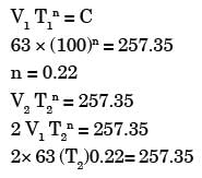
Tool life of a 10 hours is obtained when cutting with a single point tool at 63 m/min. If Taylor's constant C = 257.35, tool life on doubling the velocity will be

[ME 1996]

Detailed Solution for Past Year Questions: Cutting Tool Geometry And Tool Life - Question 5

V= 63m/min T1 = 60 hours = 600 min
C = 257.35

T2 = 25.6 min

Past Year Questions: Cutting Tool Geometry And Tool Life - Question 6

Helix angle of fast helix drill is normally

[ME 1997]

Past Year Questions: Cutting Tool Geometry And Tool Life - Question 7

For turning NiCr alloy steel at cutting speeds of 64 m/min and 100 m/min, the respective tool lives are 15 min-and 12 min. The tool life for a cutting speed of 144 m/min is

[ME 2001]

Past Year Questions: Cutting Tool Geometry And Tool Life - Question 8

Tool life testing on a lathe under dry cutting conditions gauge n and C of Taylor tool life equation as 0.12 and 130 m/min. respectively. When a coolant was used, C increased by 10%.The increased tool life with the use of coolant at a cutting speed of 90 m/min is

[ME 2001]

Detailed Solution for Past Year Questions: Cutting Tool Geometry And Tool Life - Question 8

n = 0.12, c = 130 m /min
C1 = 130 × 1.1 = 143 m/min
V1 = 90 m /min
V1 T1n = C1
90 (T1)n = 143

T1 = 47.4 min

Past Year Questions: Cutting Tool Geometry And Tool Life - Question 9

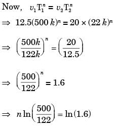
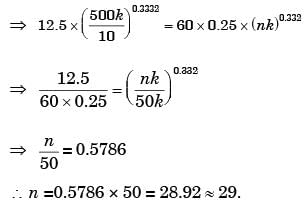
A batch of 10 cutting tools could produce 500 components while working at 50 rpm with a tool feed of 0.25 mm/rev and depth of cut of 1 mm. A similar batch of 10 tools of the same specification could produce 122 components while working at 80 rpm with a feed of 0.25 mm/rev and 1 mm depth of cut. How many components can be produced with one cutting tool at 60 rpm?

[ME 2003]

Detailed Solution for Past Year Questions: Cutting Tool Geometry And Tool Life - Question 9

Velocity of first cutting tool,
v1 = 50 × 0.25 = 12.5 mm/min
Velocity of second cutting tool,
v2 = 0.25 × 80= 20 mm/min
Since tool life = number of component produce × tool constant
∴ Tool life for first tool = T1 = 500 × k
Took life for second tool = T21 = 122 × k

⇒ n = 0.3332 Hence number of components produced by one cutting tool at 60 rpm is:

Past Year Questions: Cutting Tool Geometry And Tool Life - Question 10

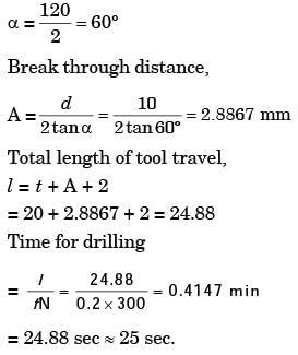
Through holes of 10 mm diameter are to be drilled in a steel plate of 20 mm thickness. Drill spindle speed is 300 rpm, feed 0.2 mm/rev and drill point angle is 120°. Assuming drill over travel of 2 mm, the time for producing a hole will be

[ME 2004]

Detailed Solution for Past Year Questions: Cutting Tool Geometry And Tool Life - Question 10

Given: Diameter of hole,
d =10 mm
Thickness of steel plate, t = 20 mm

Past Year Questions: Cutting Tool Geometry And Tool Life - Question 11

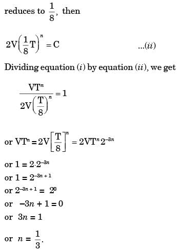
In a machining operation, doubling the cutting speed reduces the tool life to 1/8th of the original value. The exponent n in Taylor's tool life equation VTn = C. is

[ME 2004]

Detailed Solution for Past Year Questions: Cutting Tool Geometry And Tool Life - Question 11

Taylor’s tool life equation,
VTn = C ...(i)
Where, V = cutting speed and T = tool life
When cutting speed is doubled and tool life

Past Year Questions: Cutting Tool Geometry And Tool Life - Question 12

A 600 mm x 30 mm flat surface of a plate is to be finish machined on a shaper. The plate has been fixed with the 600 mm side along the tool travel direction. If the tool over-travel at each end of the plate is 20 mm, average cutting speed is 8 m/min, feed rate is 0.3 mm/stroke and the ratio of return time to cutting time of the tool is 1 : 2, the time required for machining will be

[ME 2005]

Detailed Solution for Past Year Questions: Cutting Tool Geometry And Tool Life - Question 12

Length travelled in forwarded stroke = 640 mm Number of strokes = 100
Time for cutting = 8 min
Return time = 4 min
Total time = 12 min.

Past Year Questions: Cutting Tool Geometry And Tool Life - Question 13

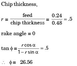
In orthogonal turning of a low carbon steel bar of diameter 150 mm with uncoated carbide tool, the cutting velocity is 90 m/min. The feed is 0.24 mm/rev and the depth of cut is 2 mm. The chip thickness obtained is 0.48 mm. If the orthogonal rake angle is zero and the principal cutting edge angle is 90°, the shear angle in degree is

[ME 2007]

Detailed Solution for Past Year Questions: Cutting Tool Geometry And Tool Life - Question 13

Past Year Questions: Cutting Tool Geometry And Tool Life - Question 14

In orthogonal turning of medium carbon steel, the specific machining energy is 2.0 J/mm3. The cutting velocity, feed and depth of cut are 120 m/min, 0.2 mm/rev and 2 mm respectively.The main cutting force in N is

[ME 2007]

Detailed Solution for Past Year Questions: Cutting Tool Geometry And Tool Life - Question 14

FC = Cutting force;
V = Cutting velocity
Specific machining energy = 2.0 J/mm3
∴ FC × V =2 × MRR
⇒ FC = 2 × .2 × 10–3 × 2 × 103 = 800 N

Past Year Questions: Cutting Tool Geometry And Tool Life - Question 15

In orthogonal turning of low carbon steel pipe with principal cutting edge angle of 90°, the main cutting force is 1000 N and the feed force is 800 N. The shear angle is 25° and orthogonal rake angle is zero. Employing Merchants theory, the ratio of friction force to normal force acting on the cutting tool is

[ME 2007]

Detailed Solution for Past Year Questions: Cutting Tool Geometry And Tool Life - Question 15

Here, ϕ = shear angle = 25º
λ = Friction angle,
α = rake angle = 0º
From Merchant''s theory, 2ϕ + λ - α = 90º
∴ λ = 90º - 50º = 40º

Past Year Questions: Cutting Tool Geometry And Tool Life - Question 16

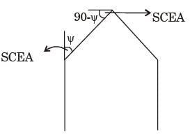
In a single point turning tool, the side rake angle and orthogonal rake angle are equal. ϕ is the principal cutting edge angle and its range is 0° ≤ f ≤ 90°. The chip flows in the orthogonal plane. The value of ϕ is closest to

[ME 2008]

Detailed Solution for Past Year Questions: Cutting Tool Geometry And Tool Life - Question 16

Side rake angle is equal to orthogonal rake angle when principle cutting edge angle become 90° and corresponding approach angle SCEA = 0°

Past Year Questions: Cutting Tool Geometry And Tool Life - Question 17

Friction at the tool-chip interface can be reduced by

[ME 2009]

Detailed Solution for Past Year Questions: Cutting Tool Geometry And Tool Life - Question 17

By increasing the cutting speed. Heat dissipation is increased hence there is lower temperature & lower friction coefficient.

Past Year Questions: Cutting Tool Geometry And Tool Life - Question 18

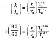
For tool A, Taylor's tool life exponent (n) is 0.45 and constant (K) is 90. Similarly for tool B, n = 0.3 and K = 60. The cutting speed (in 'm/ min) above which tool A will have a higher tool life than tool B is

[ME 2010]

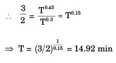
Detailed Solution for Past Year Questions: Cutting Tool Geometry And Tool Life - Question 18

Taylor's tool life equation is VTn = Constant

Given conditions for both tools:
Tool A: const ant , k1 = 90 ;
exponential constant, n1 = 0.45
Tool B: Constant ,  k2 = 60;
exponential constant, x2 = 0.3

At point of intersection
v= v2, and T1 = T2 = T

∴  90 = v1 (14.92)0.45
⇒ v1= 26.7 m /min
Above v1 = 26.7 m/min, tool A will have a higher tool life them too B.

Past Year Questions: Cutting Tool Geometry And Tool Life - Question 19

A single-point cutting tool with 12° rake angle is used to machine a steel work-piece. The depth of cut, i.e. uncut thickness is 0.81 mm. The chip thickness under orthogonal machining condition is 1.8 mm. The shear angle is approximately

[ME 2011]

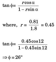
Detailed Solution for Past Year Questions: Cutting Tool Geometry And Tool Life - Question 19

Relation between shear angle (ϕ), chip thickness ratio (r) and rake angle (α) is given by

Past Year Questions: Cutting Tool Geometry And Tool Life - Question 20

In a single pass drilling operation, a through hole of 15 mm diameter is to be drilled in a steel plate of 50 mm thickness. Drill spindle speed is 500 rpm, feed is 0.2 mm/rev and drill point angle is 118°, Assuming 2 mm clearance at approach and exit, the total drill time (in seconds) is

[ME 2012]

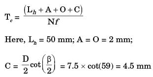
Detailed Solution for Past Year Questions: Cutting Tool Geometry And Tool Life - Question 20


N = 500 rpm; f = 0.2 mm/rev
Tc = 0.585 min or 35.1 seconds

Past Year Questions: Cutting Tool Geometry And Tool Life - Question 21

A hole of 20 mm diameter is to be drilled in a steel block of 40 mm thickness. The drilling is performed at rotational speed of 400 rpm and feed rate of 0.1 mm/rev. The required approach and over run of the drill together, is equal to the radius of drill. The drilling time (in minute) is

[ME 2014,Set-2]

Detailed Solution for Past Year Questions: Cutting Tool Geometry And Tool Life - Question 21


L = t + Ap1
Ap= 0.5 D (holes diameter)
= 10 mm
t = 40 mm

Past Year Questions: Cutting Tool Geometry And Tool Life - Question 22

The preferred option for holding an odd-shaped workpiece in a centre lathe is

[ME 2018,Set-2]

Past Year Questions: Cutting Tool Geometry And Tool Life - Question 23

Feed rate in slab milling operation is equal to

[ME 2018,Set-2]

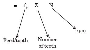
Detailed Solution for Past Year Questions: Cutting Tool Geometry And Tool Life - Question 23

Table feed or Feed rate

Past Year Questions: Cutting Tool Geometry And Tool Life - Question 24

lf the number of double strokes per minute in a shaper is calculated by (0.643 × Cutting speed in mm/min)/length of the stroke in m. Then the return speed is faster than the cutting speed by

[PI 1989]

Past Year Questions: Cutting Tool Geometry And Tool Life - Question 25

A single point cutting tool with 12° rake angle is used for orthogonal machining of a ductile material. The shear plane angle for the theoretically minimum possible shear strain to occur

[PI 1990]

Detailed Solution for Past Year Questions: Cutting Tool Geometry And Tool Life - Question 25

From Ernest & Merchant’s Theory for minimum power consumption:

Past Year Questions: Cutting Tool Geometry And Tool Life - Question 26

In a cutting test with 0.3 mm flank wear as tool failure criterion, a tool life of 10 min was obtained at a cutting velocity of 20 m/min. Taking tool life exponent as 0.25, the tool life in minutes at 40 m/min of cutting velocity will be

[PI 1993]

Detailed Solution for Past Year Questions: Cutting Tool Geometry And Tool Life - Question 26

n = 0.25 V1 = 20m /min, T1 = 10 min
V2 = 40m/min , T2 = ?

T2 = 0.625 min

Past Year Questions: Cutting Tool Geometry And Tool Life - Question 27

A workpiece of 2000 mm length and 300 mm width was machined by a planning operation with the feed set at 0.3 mm/stroke. If the machine tool executes 10 double strokes/min, the planning time for a single pass will be

[PI 1993]

Detailed Solution for Past Year Questions: Cutting Tool Geometry And Tool Life - Question 27

l = 2000 mm
w = 300 mm
f = 0.3 mm/ stroke
No. of stroke = 2 × 10
= 20 stroke / min     {double stroke}
2000 „„„
Total Machining time= 2000/20 =100 min

Past Year Questions: Cutting Tool Geometry And Tool Life - Question 28

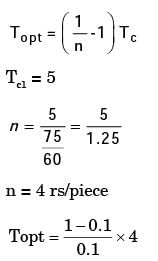
In a single pass turning operation the cutting speed is the only variable based on the cutting time cost and the cutting edge cost. The tool life for minimum cost given that cost of 1 cutting edge is Rs. 5, operator wages including the machine tool cost is Rs. 75/hour and tool life equation is VT0.1 is 100

[PI 1995]

Detailed Solution for Past Year Questions: Cutting Tool Geometry And Tool Life - Question 28


Topt = 36 min

Past Year Questions: Cutting Tool Geometry And Tool Life - Question 29

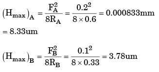
Two different tools A and B having nose radius of 0.6 mm and 0.33 mm respectively are used to machine C-45 steel employing feed rate of 0.2 mm/rev and 0.1 mm/rev respectively. The tool that gives better finish and the value of ideal surface roughness are

[PI 2002]

Detailed Solution for Past Year Questions: Cutting Tool Geometry And Tool Life - Question 29

RA = 0.6 mm. RB = 0.33 mm
FA = 0.2 mm/rev FB = 0.1 mm/rev

Tool B have higher surface finish them A.

Past Year Questions: Cutting Tool Geometry And Tool Life - Question 30

A 31.8 MM HSS drill is used to drill a hole in cast iron block 100 mm thick at cutting speed of 20 m/min and feed 0.3 mm/rev. If the over travel of drill is 4 mm and approach 9 mm, the time required to drill the hole is

[PI 2002]

Detailed Solution for Past Year Questions: Cutting Tool Geometry And Tool Life - Question 30

D = 31.8mm, t = 100 mm, V = 20m /min
f = 0.3 mm/rev,
Approach length = 4 mm
Over Travel = 9 mm

View more questions
Information about Past Year Questions: Cutting Tool Geometry And Tool Life Page
In this test you can find the Exam questions for Past Year Questions: Cutting Tool Geometry And Tool Life solved & explained in the simplest way possible. Besides giving Questions and answers for Past Year Questions: Cutting Tool Geometry And Tool Life, EduRev gives you an ample number of Online tests for practice

Top Courses for Mechanical Engineering

Download as PDF

Top Courses for Mechanical Engineering