Electrical Engineering (EE) Exam  >  Electrical Engineering (EE) Tests  >  Test: Step Response of First Order Circuits - 2 - Electrical Engineering (EE) MCQ

Test: Step Response of First Order Circuits - 2 - Electrical Engineering (EE) MCQ


Test Description

10 Questions MCQ Test - Test: Step Response of First Order Circuits - 2

Test: Step Response of First Order Circuits - 2 for Electrical Engineering (EE) 2024 is part of Electrical Engineering (EE) preparation. The Test: Step Response of First Order Circuits - 2 questions and answers have been prepared according to the Electrical Engineering (EE) exam syllabus.The Test: Step Response of First Order Circuits - 2 MCQs are made for Electrical Engineering (EE) 2024 Exam. Find important definitions, questions, notes, meanings, examples, exercises, MCQs and online tests for Test: Step Response of First Order Circuits - 2 below.
Solutions of Test: Step Response of First Order Circuits - 2 questions in English are available as part of our course for Electrical Engineering (EE) & Test: Step Response of First Order Circuits - 2 solutions in Hindi for Electrical Engineering (EE) course. Download more important topics, notes, lectures and mock test series for Electrical Engineering (EE) Exam by signing up for free. Attempt Test: Step Response of First Order Circuits - 2 | 10 questions in 30 minutes | Mock test for Electrical Engineering (EE) preparation | Free important questions MCQ to study for Electrical Engineering (EE) Exam | Download free PDF with solutions
*Answer can only contain numeric values
Test: Step Response of First Order Circuits - 2 - Question 1

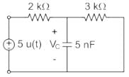
In the circuit shown below, a step input voltage of magnitude 5 V is applied at node A at time t = 0. If the capacitor has no charge for t < 0, the voltage at node P at t = 6 μs is ________ V. (Answer should be rounded off to two decimal places)
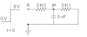

Detailed Solution for Test: Step Response of First Order Circuits - 2 - Question 1

At t ≤ 0, Vc (0) = 0 V

Time constant = τ = Req Ceq

Req = 2kΩ || 3 kΩ = 1.2 kΩ

Ceq = 5 nF

τ = RC = 6 μsec

At t = 6 μsec

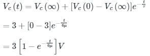
⇒ Vc(t) = 3 [1 - e-1] = 1.896 V.

Test: Step Response of First Order Circuits - 2 - Question 2

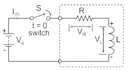
In a series RL circuit the value of inductance is 1 Henry and resistance is 10 ohms. What is the time constant of the circuit?

Detailed Solution for Test: Step Response of First Order Circuits - 2 - Question 2

Concept: 

We can use Kirchhoff’s Voltage Law, (KVL) to define the individual voltage drops that exist around the circuit and then hopefully use it to give us an expression for the flow of current.

The Time Constant, ( τ ) of the LR series circuit is given as L/R and in which V/R represents the final steady-state current value after five-time constant values.

Calculation:

L = 1 H, R = 10Ω

Time constant = 1/10 = 0.1 sec

1 Crore+ students have signed up on EduRev. Have you? Download the App
Test: Step Response of First Order Circuits - 2 - Question 3

First order system is defined as :

Detailed Solution for Test: Step Response of First Order Circuits - 2 - Question 3

First order system is defined by total number of poles and also which is same as the order of differential equation.

Test: Step Response of First Order Circuits - 2 - Question 4

The transfer function of the system is G(s) = 100/(s + 1) (s + 100). For a unit step input to the system the approximate settling time for 2% criterion is:

Detailed Solution for Test: Step Response of First Order Circuits - 2 - Question 4

G(s) = 100/(s + 1) (s + 100)
Taking the dominant pole consideration,
S = -100 pole is not taken.
G(s) = 100/s + 1
Now it is first order system, ts  4T = 4 sec.

Test: Step Response of First Order Circuits - 2 - Question 5

A first order system and its response to a unit step input are shown in figure below. The system parameters are____________

Detailed Solution for Test: Step Response of First Order Circuits - 2 - Question 5

time constant = 0.2 sec.
1/a = 0.2
a = 5
final value =
K/a = 2
K = 10.

Test: Step Response of First Order Circuits - 2 - Question 6

Calculate the peak value of the source voltage (in V) if the root-mean square voltage across the resistor and inductor in a series RL circuit is 13 V and 12 V, respectively. 

Detailed Solution for Test: Step Response of First Order Circuits - 2 - Question 6

Concept:

Source voltage RMS value of a series RL circuit will be;

Vrms = √(VR2 + VL2)

Where;

Vrms → Source voltage in RMS.

VR  → Voltage across resistance in RMS.

VL  → Voltage across inductor in RMS.

RMS voltage = Peak voltage/√(2) 

Calculation:

Given;

VR = 13 V

VL  = 12 V

Vrms = √(VR2 + VL2) = √(132 + 122) = 17.69

Peak value of the source voltage = Vrms × √2 = 25.01 V ≈ 25 V

Test: Step Response of First Order Circuits - 2 - Question 7

In an R-L circuit connected to an alternating sinusoidal voltage, size of transient current primarily depends on:

Detailed Solution for Test: Step Response of First Order Circuits - 2 - Question 7

Series RL circuit:

Let the voltage be Vs(t) = Vm sin ωt

The transient current equation is 

where

Vm = Peak value of voltage

θ = Peak value of impedance angle

ω = angular frequency

R = Resistance

L = Inductance

α = instant at which the circuit is closed

θ = Impedance angle

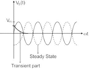
The exponential decay term represents the transient term and the remaining is the steady-state term.

The response is shown below;

In the steady-state, the RLC circuit elements give a response that is in synchronization to the input frequency.

Because transient analysis expressions consist of exponential decay terms.

Size of transient current primarily depends on the instant in the voltage cycle at which circuit is closed i.e. it depends on α value.

*Answer can only contain numeric values
Test: Step Response of First Order Circuits - 2 - Question 8

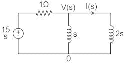
In the circuit shown, the voltage VIN(t) is described by:

where t is in seconds. The time (in seconds) at which the current I in the circuit will reach the value 2 Amperes is ________.
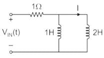

Detailed Solution for Test: Step Response of First Order Circuits - 2 - Question 8

Concept:

Calculation:

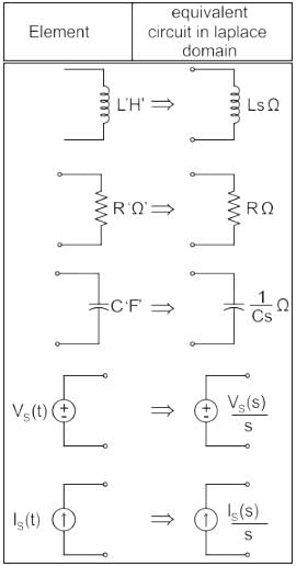
Taking Laplace to transform with given conditions

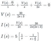
Applying KCL at V(s) node:

Taking the inverse Laplace transform, we get:

i(t) = 5(1 – e-3t/2)

Given, at t = t0

i = 2 A

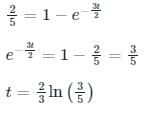
2 = 5 (1 – e-3t/2)

t = 0.3405 sec

Test: Step Response of First Order Circuits - 2 - Question 9

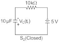
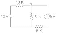
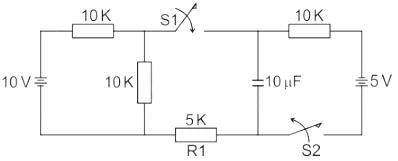
In the circuit shown below, switch S1 and S2 are in open and close position respectively for long time. At t = t0, switch S1 is closed and switch S2 is opened. What would be the current through R1 immediately after the transition of switches?
Detailed Solution for Test: Step Response of First Order Circuits - 2 - Question 9

Concept:

A capacitor doesn’t allow a sudden change in voltage, i.e. Vc(0+) = Vc(0-).

Similarly, an inductor doesn’t allow a sudden change in current, i.e. iL(0+) = iL(0-)

Calculation:

The circuit for t = t0- is as shown,

Vc(t0-) = 5V as shown above,

At t = t0+, the circuit will be as shown, in which the capacitor will be at 5V (∵ Vc(0+) = Vc(0-))

To find the voltage at node ‘x’, we apply KCL to get,

Now the required current through R1 = 5KΩ, immediately after the transition of switches is


Test: Step Response of First Order Circuits - 2 - Question 10

Assertion (A.: It is observed that step function is first derivative of a ramp function and impulse function is first derivative of a step function.
Reason (R): From the derived time response expression it is concluded that the output time response also follows the same sequence as that of input functions.

Detailed Solution for Test: Step Response of First Order Circuits - 2 - Question 10

If response due to one standard signal is known then response due to other signals can also be derived.

Information about Test: Step Response of First Order Circuits - 2 Page
In this test you can find the Exam questions for Test: Step Response of First Order Circuits - 2 solved & explained in the simplest way possible. Besides giving Questions and answers for Test: Step Response of First Order Circuits - 2, EduRev gives you an ample number of Online tests for practice

Top Courses for Electrical Engineering (EE)

Download as PDF

Top Courses for Electrical Engineering (EE)