Electronics and Communication Engineering (ECE) Exam  >  Electronics and Communication Engineering (ECE) Tests  >  Test: Mutual Inductance - 1 - Electronics and Communication Engineering (ECE) MCQ

Test: Mutual Inductance - 1 - Electronics and Communication Engineering (ECE) MCQ


Test Description

10 Questions MCQ Test - Test: Mutual Inductance - 1

Test: Mutual Inductance - 1 for Electronics and Communication Engineering (ECE) 2025 is part of Electronics and Communication Engineering (ECE) preparation. The Test: Mutual Inductance - 1 questions and answers have been prepared according to the Electronics and Communication Engineering (ECE) exam syllabus.The Test: Mutual Inductance - 1 MCQs are made for Electronics and Communication Engineering (ECE) 2025 Exam. Find important definitions, questions, notes, meanings, examples, exercises, MCQs and online tests for Test: Mutual Inductance - 1 below.
Solutions of Test: Mutual Inductance - 1 questions in English are available as part of our course for Electronics and Communication Engineering (ECE) & Test: Mutual Inductance - 1 solutions in Hindi for Electronics and Communication Engineering (ECE) course. Download more important topics, notes, lectures and mock test series for Electronics and Communication Engineering (ECE) Exam by signing up for free. Attempt Test: Mutual Inductance - 1 | 10 questions in 30 minutes | Mock test for Electronics and Communication Engineering (ECE) preparation | Free important questions MCQ to study for Electronics and Communication Engineering (ECE) Exam | Download free PDF with solutions
Test: Mutual Inductance - 1 - Question 1

A 5 H coil is coupled with a 20 H coil. What could be the maximum value of mutual inductance between them considering no flux linkage?

Detailed Solution for Test: Mutual Inductance - 1 - Question 1

Concept:
Mutual inductance:

  • When two coils are brought in proximity with each other the magnetic field in one coil tends to link with the other.
  • It leads to the generation of voltage in the second coil.
  • This property of a coil that affects or changes the current in the second coil is called mutual inductance.
  • Mathematically, mutual inductance (M) between two coils of inductance, L1 and L2 is given by


where K is the coefficient of coupling.
K ranges from 0 to 1.
When two coils are not in proximity to each other, then flux linkage between them will be zero, so, the value of K would be 1 in that case.
Given:
L1 = 5 H and L2 = 20 H.
Here K = 1.
From 1, mutual inductance (M) can be given as

= 10 H.

Test: Mutual Inductance - 1 - Question 2

Identify the INCORRECT statement among the given options regarding mutual inductance.

Detailed Solution for Test: Mutual Inductance - 1 - Question 2

Mutual Inductance:

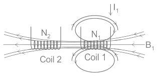
  • The mutual inductance of two coils is defined as the emf induced due to the magnetic field in one coil opposing the change of current and voltage in another coil. 
  • Thus mutual inductance depends on the value of current in the circuit.
  • That means the two coils are magnetically linked together due to the change in magnetic flux.
  • The magnetic field or flux of one coil links with another coil. This is denoted by M.
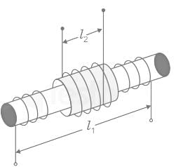
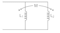
  • The above figure shows that mutual inductance is a geometric quantity.
  • The current flowing in one coil induces the voltage in another coil due to the change in magnetic flux.
  • The amount of magnetic flux linked with the two coils is directly proportional to the mutual inductance and current change.

Mutual inductance is given by 

Where μ0 = Permeability of free space = 4π × 10-7 H/m
μr = Relative permeability of the core
N1 = Number of turns of coil 1
N2 = Number of turns of coil 2
A = Cross-sectional area in m2

  • The mutual inductance of two coils can be increased by placing them on a soft iron core or by increasing the number of turns of the two coils.
  • Unity coupling exists between the two coils when they are tightly wound on a soft iron core. The leakage of flux would be small.
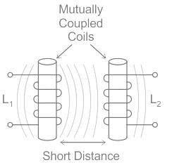
  • If the distance between the two coils is short, then the magnetic flux produced in the first coil interacts with all the turns of the second coil, which results in large EMF and mutual inductance.
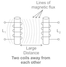
  • If the two coils are farther and apart from each other at different angles, then the induced magnetic flux in the first coil generates weak or small EMF in the second coil.
  • Hence the mutual inductance will also be small.
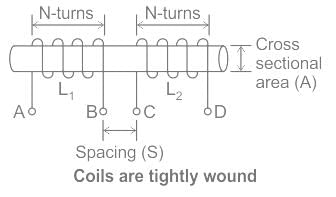
  • Thus the value of this mainly depends on the positioning and spacing of two coils on a soft iron core.
  • Consider the figure, which shows that the two coils are tightly wound one on the top of the soft iron core.
  • The change of current in the first coil produces a magnetic field and passes the magnetic lines through the second coil, which is used to calculate mutual inductance.
  • A transformer works on the principles of "electromagnetic induction" as a mutual induction i.e. transformers have a large mutual inductance.
  • Mutual inductance is the main operating principle of generators, motors, and transformers.
    Any electrical device having components that tend to interact with another magnetic field also follows the same principle.
  • The interaction is usually brought about by a mutual induction where the current flowing in one coil generates a voltage in a secondary coil.
1 Crore+ students have signed up on EduRev. Have you? Download the App
Test: Mutual Inductance - 1 - Question 3

What is the basic operating principle of mutual induction?

Detailed Solution for Test: Mutual Inductance - 1 - Question 3
  • Mutual Inductance is the basic operating principle of the transformer, motors, generators, and any other electrical component that interacts with another magnetic field. Then we can define mutual induction as the current flowing in one coil that induces a voltage in an adjacent coil.
  • But mutual inductance can also be a bad thing as “stray” or “leakage” inductance from a coil can interfere with the operation of another adjacent component by means of electromagnetic induction, so some form of electrical screening to a ground potential may be required.
  • The amount of mutual inductance that links one coil to another depends very much on the relative positioning of the two coils.

    Mutual Inductance between Coils is given by:

    Where:
    µo is the permeability of free space (4π x 10-7)
    µr is the relative permeability of the soft iron core
    N1, N2 is in the number of coil turns
    A is in the cross-sectional area in m2
    L is the coil's length in meters.

Test: Mutual Inductance - 1 - Question 4

Two identical coils X and Y of 500 turns each lie in parallel planes such that 80% of flux produced by one coil links with the other. If a current of 5 A flowing in X produces a flux of 10 mWb in it, find the mutual inductance between X and Y

Detailed Solution for Test: Mutual Inductance - 1 - Question 4

Concept:
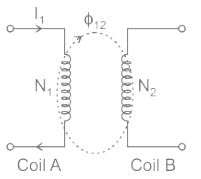
Consider two coils having self-inductance L1 and L2 placed very close to each other. Let the number of turns of the two coils be N1 and N2 respectively. Let coil A carries current I1 and coil B carries current I2.

Due to current I1, the flux produced is ϕ1 which links with both the coils. Then the mutual inductance between two coils can be written as

Here, ϕ12 is the part of the flux ϕ1 linking with the coil 2
Calculation:
Number of turns = N1 = N2 = 500
Current (I) = 5 A
Flux produced in coil X (ϕ1) = 10 mwb
Flux linked with Y (ϕ12) = 80% of flux produced in coil 1 = 8 mwb
Mutual inductance 

Test: Mutual Inductance - 1 - Question 5

Two coupled coils with L1 = 0.5 H and L2 = 4.0 H have a co-efficient of coupling 0.8. Find maximum value of the inductance EMF in the coil 2 if a current of i1 = 20 sin 314t A is passed in coil 1.

Detailed Solution for Test: Mutual Inductance - 1 - Question 5

Concept :
Self-inductance is the property of the current-carrying coil that resists or opposes the change of current flowing through it. This occurs mainly due to the self-induced emf produced in the coil itself. In simple terms, we can also say that self-inductance is a phenomenon where there is the induction of a voltage in a current-carrying wire.
Self-inductance, usually just called inductance, L is the ratio between the induced voltage and the rate of change of the current
V1(t) = L (di1/dt)
Mutual Inductance between the two coils is defined as the property of the coil due to which it opposes the change of current in the other coil, or you can say in the neighboring coil. When the current in the neighboring coil changes, the flux sets up in the coil and, because of this, changing flux emf is induced in the coil called Mutually Induced emf and, the phenomenon is known as Mutual Inductance.
V2(t) = M (di1/dt)
Coefficient of Coupling :


The amount of coupling between the inductively coupled coils is expressed in terms of the coefficient of coupling, which is defined as

where M = mutual inductance between the coils
L1 = self-inductance of the first coil, and
L2 = self-inductance of the second coil

  • The coefficient of coupling is always less than unity and has a maximum value of 1 (or 100%).
  • This case, for which K = 1, is called perfect coupling when the entire flux of one coil links the other.
  • The greater the coefficient of coupling between the two coils, the greater the mutual inductance between them, and vice-versa.

Calculations :
Given 
L1 = 0.5 H
L2 = 4 H
K = 0.8
I = 20 sin 314t
The induced emf in coil 2 due to current in coil 1 is given by
V2 = M (di1 / dt)

M = 1.13 H
V2 = 1.13 d/dt (20 sin 314t)
V2 = 1.13 ×  20 × 314 × cos 314t
The maximum value of V2 = 1.13 × 20 × 314 = 7.1 kV

Test: Mutual Inductance - 1 - Question 6

Two inductors L1 = 20 mH and L2 = 40 mH are connected in series so that their equivalent inductance is 50 mH. The mutual inductance between the two coils is _______.

Detailed Solution for Test: Mutual Inductance - 1 - Question 6

Concept:
The equivalent inductance of series aiding connection is

Leq = L1 + L2 + 2M
The equivalent inductance of series opposing connection is

Leq = L1 + L2 – 2M
Calculation:
Given:
L1 = 20 mH
L2 = 40 mH
Leq = 50 mH
From the given data we can conclude that series opposing connection will be considered as the mutual index cannot be negative.
Leq = L1 + L2 – 2M
50 = 40 + 20 - 2M
M = 5 mH

Test: Mutual Inductance - 1 - Question 7

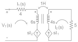
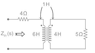
The input impedance, Zin (s), for the network shown is
Detailed Solution for Test: Mutual Inductance - 1 - Question 7

Concept:
Mutual Inductance:

When two coils are placed close to each other, a change in current in the first coil produces a change in magnetic flux, which cuts not only the coil itself but also the second coil as well. The change in the flux induces a voltage in the second coil, this voltage is called induced voltage and the two coils are said to have a mutual inductance.
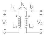
Consider a pair of coupled inductors with self-inductance L1 and L2, magnetically coupled through coupling coefficient k.

Input and output voltage expressions are given as
V1 = jωL1I1 + jωMI2   ...(1)
V2 = jωL2I2 + jωMI1    ...(2)
Where,
ω = 2πf

M = Mutual inductance
L1 = Inductance of coil one
L2 = Inductance of coil two
Calculation:
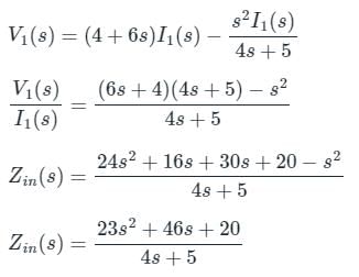
The given circuit in the Laplace domain is 

Apply KVL in the input loop,
V1(s) = (4 + 6s)I1(s) + sI2(s)  ...(1)
Apply KVL in the output loop
I2(s)[5 +4s] + sI1(s) = 0

Substitute I2(s) in equation(1)

Test: Mutual Inductance - 1 - Question 8

10 μF capacitor is connected across the secondary winding of a high-frequency transformer having primary to secondary turns ratio 5: 2. What is the value of capacitance seen across primary?

Detailed Solution for Test: Mutual Inductance - 1 - Question 8

Concept:
For a transformer, the input impedance (Zin) for a given load impedance (ZL) is given by:

Where Zin is also called the Reflected impedance since it appears as if the load impedance is reflected in the primary side.
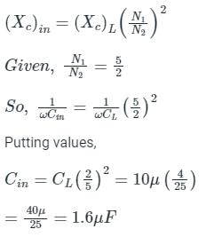
Calculation:

Therefore the value of capacitance seen across the primary is:

Test: Mutual Inductance - 1 - Question 9

A transformer has 350 primary turns and 1050 secondary turns. The primary winding is connected across a 230 V, 50 Hz supply. The induced EMF in the secondary will be

Detailed Solution for Test: Mutual Inductance - 1 - Question 9

Concept:

  • The transformer basically changes the level of voltages from one value to the other at a constant frequency.
  • It is a static device that transforms electrical energy from one circuit to another without any direct electrical connection between them.
  • This is achieved with the help of mutual induction between the two windings.
  • In a transformer electrical energy changes to electrical and heat energy.

In a transformer, the relation between the number of turns, current, and voltages is given by:

N1 and N2 = number of turns in the primary and secondary windings respectively
V1 and I1 = Voltage and current respectively at the primary end
V2 and I2 = Voltage and current respectively at the secondary end

Calculation:
Given V1 = 230 V, 50 Hz supply
N1 = 350
N2 = 1050

Putting on the respective values, we get:

V2 = 690 V
The frequency of the secondary generated voltage will be the same as the input frequency.

Test: Mutual Inductance - 1 - Question 10

Two inductors whose self-inductance is 80 mH and 60 mH are connected in parallel aiding. The equivalent inductance of the combination is 48.75 mH. Calculate their mutual inductance.

Detailed Solution for Test: Mutual Inductance - 1 - Question 10

Concept:
For Additive coupling (assists the self-inductance):


Calculation:
Given: L1 = 80 mH L2 = 60 mH
Leq = 48.75 mH
Mutual inductance can be calculated from equation (1):

2M2 - 195M + 4050 = 0
By using the following formula we can find the roots

On solving the above expression we get:
M = 30 and M = 135/2.
From the given options we can say that M = 30 mH is the correct answer.

Information about Test: Mutual Inductance - 1 Page
In this test you can find the Exam questions for Test: Mutual Inductance - 1 solved & explained in the simplest way possible. Besides giving Questions and answers for Test: Mutual Inductance - 1, EduRev gives you an ample number of Online tests for practice

Top Courses for Electronics and Communication Engineering (ECE)

Download as PDF

Top Courses for Electronics and Communication Engineering (ECE)