Electrical Engineering (EE) Exam  >  Electrical Engineering (EE) Tests  >  Test: Instrument Transformer - 2 - Electrical Engineering (EE) MCQ

Test: Instrument Transformer - 2 - Electrical Engineering (EE) MCQ


Test Description

10 Questions MCQ Test - Test: Instrument Transformer - 2

Test: Instrument Transformer - 2 for Electrical Engineering (EE) 2024 is part of Electrical Engineering (EE) preparation. The Test: Instrument Transformer - 2 questions and answers have been prepared according to the Electrical Engineering (EE) exam syllabus.The Test: Instrument Transformer - 2 MCQs are made for Electrical Engineering (EE) 2024 Exam. Find important definitions, questions, notes, meanings, examples, exercises, MCQs and online tests for Test: Instrument Transformer - 2 below.
Solutions of Test: Instrument Transformer - 2 questions in English are available as part of our course for Electrical Engineering (EE) & Test: Instrument Transformer - 2 solutions in Hindi for Electrical Engineering (EE) course. Download more important topics, notes, lectures and mock test series for Electrical Engineering (EE) Exam by signing up for free. Attempt Test: Instrument Transformer - 2 | 10 questions in 30 minutes | Mock test for Electrical Engineering (EE) preparation | Free important questions MCQ to study for Electrical Engineering (EE) Exam | Download free PDF with solutions
Test: Instrument Transformer - 2 - Question 1

The primary winding of a current transformer is connected in _________ with the line carrying the main current and the secondary winding is directly connected across ___________.

Detailed Solution for Test: Instrument Transformer - 2 - Question 1

Current Transformer:

  • The Current Transformer ( C.T. ), is a type of “instrument transformer” that is designed to produce an alternating current in its secondary winding which is proportional to the current being measured in its primary.
  • The transformer's primary winding is physically connected in series with the conductor that carries the measured current flowing in the circuit.
  • Generally, current transformers and ammeters are used together as a matched pair in which the design of the current transformer is such as to provide a maximum secondary current corresponding to a full-scale deflection on the ammeter.
  • Current transformers “step-down” current levels from thousands of amperes down to standard output of a known ratio to either 5 Amps or 1 Amp for normal operation.

Test: Instrument Transformer - 2 - Question 2

Up to a voltage of __________, Potential Transformers (PTs) are usually of dry type.

Detailed Solution for Test: Instrument Transformer - 2 - Question 2


Potential transformer:

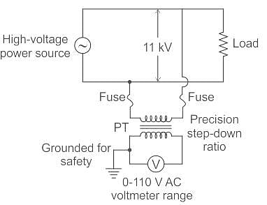
  • The potential transformer is a voltage step-down transformer that reduces the voltage of a high voltage circuit to a lower level for the purpose of measurement. 
  • The primary winding consists of a large number of turns which is connected across the high voltage side or the line in which measurements have to be taken or to be protected.
  • The secondary winding has a lesser number of turns which is connected to the voltmeters.
  • The primaries of PT are rated from 400 V to several thousand volts and secondaries are always for 110 V.
  • Up to voltages of 5,000, potential transformers are usually of the dry type.
  • If the voltage is between 5,000 and 13,800 volts, then the transformer may be either dry type or oil-immersed type.
  • For the voltages above 13,800 volts, they are always an oil-immersed type of transformer.
1 Crore+ students have signed up on EduRev. Have you? Download the App
Test: Instrument Transformer - 2 - Question 3

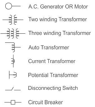
The below symbol which is used in single line diagrams represents ________

Detailed Solution for Test: Instrument Transformer - 2 - Question 3

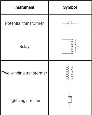
The symbols of different equipment used in single line diagram are shown below.


Hence, the given symbol is for the potential transformer.

Test: Instrument Transformer - 2 - Question 4

The ratio error in current transformer is attributed to:

Detailed Solution for Test: Instrument Transformer - 2 - Question 4

Ratio error in current transformer:

  • In the current transformer, the primary current Ip should be exactly equal to the secondary current multiplied by turns ratio, i.e. KTIs.
  • But there is a difference between primary current Ip should be exactly equal to the secondary current multiplied by the turns ratio.
  • This difference is contributed by the core excitation or magnetizing component of no-load current.
  • The error in the current transformer introduced due to this difference is called current error or ratio error.
     

The actual ratio of transformation varies with operating conditions and the error in secondary voltage is defined as
Percentage ratio error 


Kn is the nominal ratio
R is the actual ratio
It can be reduced by secondary turns compensation i.e. slightly decreasing the secondary turns.

Phase angle error:
In an ideal voltage transformer, there should not be any phase difference between the primary voltage and the secondary voltage reversed. However, in an actual transformer, there exists a phase difference between Vo­ and V­s reversed.
The phase angle is taken as +ve when secondary voltage reversed leads the primary voltage.
The angle is -ve when the secondary voltage reversed lags the primary voltage.
It can be reduced by keeping the primary and secondary windings are wound as closely as possible.

Test: Instrument Transformer - 2 - Question 5

A current carrying conductor is wrapped eight times around the jaw of a clamp-on meter that reads 50 A. What will be the actual value of the conductor current?

Detailed Solution for Test: Instrument Transformer - 2 - Question 5

Concept:

Current transformer:

  • A current transformer is a device that is used to measure high alternating current in a conductor.
  • In the figure shown below the conductor act as the primary winding of a single turn that passed through the circular laminated iron core.
  • The secondary winding consists of a large number of turns of fine wire wrapped around the core.
  • Due to transformer action, the secondary current transforms into a lower value.


Let, Np is a number of turn in the primary winding
Ns is the number of turns in the secondary winding.
Ip and Is are primary and secondary turns respectively.
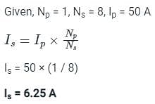
Therefore, the secondary current is given by,

  • Therefore, the current transformer changes the current into a lower value that can easily be measured by the measuring instrument.
  • Along with a Potential transformer (PT), a current transformer (CT) can measure Power and energy also.
  • Hence, CT used with Ammeter, Wattmeter, and Watt-hour meter.

Calculation:

Test: Instrument Transformer - 2 - Question 6

Instrument transformers are

Detailed Solution for Test: Instrument Transformer - 2 - Question 6

In high voltage A.C. circuits, the measurement cannot be done by using the method of extension of ranges of low range meters by providing suitable shunts.
In such conditions, specially constructed accurate ratio transformers are used. These transformers are used to isolate the instruments from high current and high voltage A.C. circuits.
These are generally classified as
(i) Current transformer - large alternating currents can be measured
(ii) Potential transformer - High voltages can be measured

Test: Instrument Transformer - 2 - Question 7

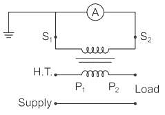
The following is a circuit representation of

Detailed Solution for Test: Instrument Transformer - 2 - Question 7

Test: Instrument Transformer - 2 - Question 8

The primary of a _______ should never be energised when its secondary is open circuited.

Detailed Solution for Test: Instrument Transformer - 2 - Question 8

Current Transformer:
The secondary side of the current transformer is always kept short-circuited in order to avoid core saturation and high voltage induction so that the current transformer can be used to measure high values of currents.

  • The current transformer works on the principle of shorted secondary.
  • It means that the burden on the system Zb is equal to 0.
  • Thus, the current transformer produces a current in its secondary which is proportional to the current in its primary..
Test: Instrument Transformer - 2 - Question 9

A current transformer has double turn primary and a 100 turn secondary winding. The secondary draws current of 6 A and magnetising ampere-turns is 60 A. What is actual transformation ratio?

Detailed Solution for Test: Instrument Transformer - 2 - Question 9

Magnetizing ampere-turns = 60 A = NI
Magnetizing current (Im) = 30 A
Number of primary turns (N1) = 2
Number of secondary turns (N2) = 100


Exciting current (I0) = Im = 30 A

The rated secondary current (I2) = 6 A

Reflected secondary current = nI2 = 50 x 6 = 300 A

Test: Instrument Transformer - 2 - Question 10

Under operating conditions, the secondary of a current transformer is always short-circuited because of ________.

Detailed Solution for Test: Instrument Transformer - 2 - Question 10

The secondary side of the current transformer is always kept short-circuited in order to avoid core saturation and high voltage induction so that the current transformer can be used to measure high values of currents.

  • Current transformer works on the principle of shorted secondary
  • It means that the burden on the system Zb is equal to 0
  • Thus, the current transformer produces a current in its secondary which is proportional to the current in its primary
Information about Test: Instrument Transformer - 2 Page
In this test you can find the Exam questions for Test: Instrument Transformer - 2 solved & explained in the simplest way possible. Besides giving Questions and answers for Test: Instrument Transformer - 2, EduRev gives you an ample number of Online tests for practice

Top Courses for Electrical Engineering (EE)

Download as PDF

Top Courses for Electrical Engineering (EE)