Electrical Engineering (EE) Exam  >  Electrical Engineering (EE) Test  >  Electrical and Electronic Measurements  >  Test: Measurement of Resistance - 2 - Electrical Engineering (EE) MCQ

Measurement of Resistance - 2 - GATE EE Electrical and Electronic Measurements


MCQ Practice Test & Solutions: Test: Measurement of Resistance - 2 (10 Questions)

You can prepare effectively for Electrical Engineering (EE) Electrical and Electronic Measurements with this dedicated MCQ Practice Test (available with solutions) on the important topic of "Test: Measurement of Resistance - 2". These 10 questions have been designed by the experts with the latest curriculum of Electrical Engineering (EE) 2026, to help you master the concept.

Test Highlights:

  • - Format: Multiple Choice Questions (MCQ)
  • - Duration: 30 minutes
  • - Number of Questions: 10

Sign up on EduRev for free to attempt this test and track your preparation progress.

Test: Measurement of Resistance - 2 - Question 1

Which is the Important Part of megger?

Detailed Solution: Question 1

Megger:

1.Definition:

  • The Megger is the instrument uses for measuring the resistance of the insulation.
  • It works on the principle of comparison, i.e., the resistance of the insulation is compared with the known value of resistance.
  • The Megger has three coils two pressure coils (control coil) and one current coil. The pressure coil rotates the moving coil in the anticlockwise direction, whereas the current coil rotates it in the clockwise direction.
  • If the resistance of the insulation is high, the pointer of the moving coil deflects towards the infinity, and if it is low, then the pointer indicates zero resistance.
  • The accuracy of the Megger is high as compared to other instruments.

2. Construction of Megger:

  • It is the combination of DC Generator and Ohm Meter.
  • The Megger has one current coil and the two voltage coils V1 and V2.
  • Deflecting coil or current coil connected in series and allows flowing the electric current taken by the circuit being tested.
  • The control coil is also known as the pressure coil is connected across the circuit.
  • D.C generator or Battery connection: The voltage is generated by connecting the hand-driven generator.
  • Deflecting and Control coil: Connected parallel to the generator, mounted at a right angle to each other, and maintain polarities in such a way to produced torque in opposite direction.
  • Permanent Magnets: Produce magnetic field to deflect pointer with North-South pole magnet.
  • Pointer: One end of the pointer connected with coil another end deflects on a scale from infinity to zero.
  • Scale: A scale is provided in the front-top of the megger from range ‘zero’ to ‘infinity’, enable us to read the value.
  • Pressure Coil Resistance and Current Coil Resistance: Protect instrument from any damage because of low external electrical resistance under test.


3. Working Principle of Megger:

  • The voltage coil V1 is passed over the magnet connected to the generator. When the pointer of the PMMC instrument deflects towards infinity, it means that the voltage coil remains in the weak magnetic field and thus experienced the very little torque.
  • The torque experienced by the coil increases when it moves insides the strong magnetic field. The coil experience the maximum torque under the pole faces and the pointer set at the zero end of the resistance scale.
  • For improving the torque, the voltage coil V2 is used. The coil V2 is so allocated that when the pointer deflects from infinity to zero coil moves into a stronger magnetic field.
  • Resultant torque is directly proportional to voltage and inversely proportional to current.
  • In Megger, the combined action of both the voltage coils V1 and V2 are considered. The coil comprises a spring of variable stiffness. It is stiff near the zero ends of the coil and becomes very weak near the infinity end of the spring.
  • A current limiting resistor is connected in series with a control and deflecting coil to protect damage in case of very low resistance in the external circuit.
  • The spring compresses the low resistance portion and opens the high resistance of the spring, which is the great advantage of the Megger because it is used for measuring the insulation of the resistance which is usually very high.
  • The megger instrument simply connects across the insulation to be tested and operated it for a short, specific time period (60 seconds is usually recommended).
  • For more than 60 seconds the temperature and humidity as well as the condition of insulation affect the reading.

Test: Measurement of Resistance - 2 - Question 2

Which instrument is used for conducting tests after wire installation?

Detailed Solution: Question 2

After completion of the wire installation, we do the following test:

(1) Polarity Test:

  • In this test If the switch is inserted in the live line, the megger will indicate ‘zero’ reading.
  • On the other hand, if the pointer of the megger shows ‘infinity’ or any high value of resistance, it may be concluded that the switch has not been inserted in the live wire; it has been placed in the neutral or some other wire

(2) To Test the Effectiveness of Earth resistance:

In megger, the arrangement is such that when the handle of the instrument is turned, alternating current flows through the earth, but direct current flows through the device for measuring the earth resistance.

As both of these tests is performed by using Megger only. So, megger is the correct option.

Note:

Test: Measurement of Resistance - 2 - Question 3

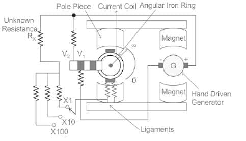
Which among the following is a method of absolute measurement of resistance?

Detailed Solution: Question 3

  • There are many methods by which resistance can be measured absolutely in the electromagnetic system of units
  • The first absolute measurements of resistance were made by Kirchhoff in 1849
  • Weber proposed three methods by which the resistance of a wire can be determined absolutely
  • The absolute measurement of resistance is done by Lorentz method

Test: Measurement of Resistance - 2 - Question 4

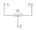
When a capacitor was connected across the terminals of an ohm meter, the pointer indicated a low resistance initially and then slowly came back to very high resistance. This indicates that capacitor is

Detailed Solution: Question 4

Concept: 

Capacitor behavior:

  • Ohmmeter uses dc voltage (battery) to measure the unknown resistance.
  • Then the capacitor is subjected to dc source, initially, it acts as a short circuit and at steady-state, it acts as an open circuit.
  • At the time when the ohmmeter is connected to the capacitor, the capacitor acts as a short circuit, so low resistance is indicated.
  • After some time, the capacitor behaves as an open-circuit, so the pointer moves to the final position.
  • This states that the capacitor is in very good condition to be used.

Important Points

  • Capacitive reactance is given by Xc = 1/(2πfc) where f = frequency and c = value of capacitance
  • Frequency f = 1/T (Time period) 
  • At the instant when the capacitor is connected to dc source, then V volt is reached in 0 sec so the time period is 0 sec.
  • This makes the frequency to be infinity, therefore capacitive reactance becomes zero.
  • That's why the capacitor acts as a short circuit initially when the dc source is applied. 
  • Now capacitor starts charging and voltage is developed across it.
  • When the steady-state voltage across the capacitor is equal to source voltage, then after that it doesn't allow any current to pass through it.
  • Therefore, acts as highly resistive or this can also be seen when at steady-state, frequency is zero, so capacitive reactance becomes infinity.
  • That's why the capacitor blocks dc at the steady-state condition.

Test: Measurement of Resistance - 2 - Question 5

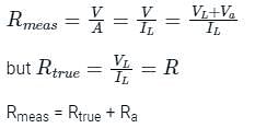
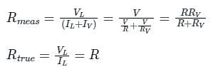
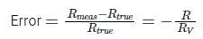
In measuring resistance by voltmeter-ammeter method, the voltmeter can be connected either across supply or across the resistance. If the resistance is low, the voltmeter should be connected

Detailed Solution: Question 5

V–A Method:

In this method, the voltmeter is connected across the supply.

V = Voltmeter reading

A = Ammeter reading

VL = Voltage across load R.

IL = Current flowing through load R.

R = Unknown resistance to be measured

R= Internal resistance of the ammeter

Va= voltage drop across ammeter.

V = V+ Va

So, in this method measured value is greater than the true value. This error is due to an ammeter.

The error is high for very low values of unknown resistance R.

A–V Method:

In this method, the voltmeter is connected across the resistance.

V = Voltmeter reading

A = Ammeter reading

V= Voltage across load R.

R = Unknown resistance to be measured

I= Current flowing through load R.

I= Current flowing through the voltmeter.

The measured value is less than the true value. In this method, the error is due to the voltmeter.

The error is low for very low values of unknown resistance R.

Observations:

  • In both methods errors due to load side instruments.
  • V – A method is best suitable for high resistances in the medium range.
  • A – V method is best suitable for low resistances in the medium range.

Test: Measurement of Resistance - 2 - Question 6

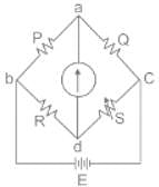
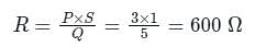
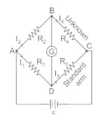
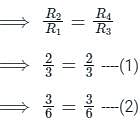
Find the unknown resistance value in a given circuit, given the bridge is balanced.

Detailed Solution: Question 6

Concept:


  • A Wheatstone bridge is a special arrangement of 4 resistors. It can be used to find an unknown resistance.
  • If the Wheatstone bridge is balanced, there will be no current flowing through the galvanometer.
  • Wheatstone bridge is used to measure the resistance with the help of a comparison method.
  • The Wheatstone bridge work on the principle of null deflection.

​The bridge is balanced when: P/R = Q/S

Calculation:

Given that,

For a whetstone network, we have four resistance P, Q, R, and S, and their values are

P = 25 Ω

Q = 15 Ω

R = 17 Ω

S = ?

Balanced bridge: The bridge is said to be balanced when deflection in the galvanometer is zero i.e. no current flows through the galvanometer. 

In the balanced condition P/R = Q/S, on mutually changing the position of cell and galvanometer, this condition will not change.

Test: Measurement of Resistance - 2 - Question 7

A megger is a device used for measuring:

Detailed Solution: Question 7

The Megger method is used for the measurement of the high value of resistance. And this is best suitable for the measurement of insulation resistance of cables.

Additional Information

To measure High resistance Three(3) terminals are required.

Where,

Terminals 1 and 2 are input terminals, Terminal 3 is called Guard Terminal

Guard Terminal is used to eliminate or bypass Leakage currents while measuring.

Examples of High Resistance Materials:

  • Cable Insulation Resistance.
  • All Motors, generators, and transformers winding's insulation resistance.
  • All semiconductor devices when reverse biased.

Methods to measure High Resistance:

  1. ​Loss of charge method.
  2. Direct-Deflection method.
  3. Mega ohm Bridge.
  4. Meggar.

Test: Measurement of Resistance - 2 - Question 8

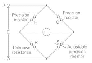
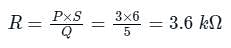
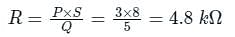
In case of the Wheatstone bridge shown in the below circuit diagram P = 3 kΩ and Q = 5 kΩ. The null value for the galvanometer is obtained when S = 6 kΩ. Find the value of R and the resistance measurement range of the bridge if ‘S’ value varies from 1 kΩ to 8 kΩ

Detailed Solution: Question 8

Concept


Wheatstone bridge:

It is an arrangement of four resistance which can be used to measure one of them in terms of rest. Here arms AB and BC are called ratio arm and arms AC and BD are called conjugate arms.

Where R is unknown resistance & S is standard resistance.

The bridge is said to be balanced when deflection in the galvanometer is zero i.e. no current flows through the galvanometer or in other words VB = VD.

In the balanced condition

P/Q = S/R

Explanation:

We know that the balanced condition of a bridge

P × S = R × Q


Now take minimum value of S = 1 kΩ

Now take the maximum value of S = 8 kΩ

∴ Range of bridge = 600 Ω to 4.8 kΩ

Test: Measurement of Resistance - 2 - Question 9

Which of the following statement is NOT correct?

    Detailed Solution: Question 9

    Test: Measurement of Resistance - 2 - Question 10

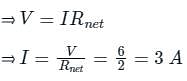
    Find the value of source current (I) from the circuit as shown below

    Detailed Solution: Question 10

    Concept:

    Wheatstone Bridge:

    • The Wheatstone Bridge has four resistors R1, R2, R3, and R4.
    • A Voltage source is connected across one pair of diagonally opposite points A and C. This is called the battery arm.
    • Between the other two vertices, B and D, a galvanometer G is connected. This is called the Galvanometer arm.
    • For the sake of simplicity, let us assume that the cell has no internal resistance.

    Balanced Bridge:

    • The resistors are arranged in such a manner that the current through the galvanometer is zero, i.e. Ig = 0.
    • The bridge is said to be balanced when deflection in the galvanometer is zero i.e. no current flows through the galvanometer or in other words VB = VD.
    • Under the balanced condition,

    • The above equation relates the four resistors is called the balance condition of the Wheatstone Bridge for which the galvanometer will show zero or null deflection.

    Explanation:

    According to the question given below:

    • In the above figure, there are two sets of Balanced Wheatstone bridges.
    • We know the condition for a balanced Wheatstone bridge is

    • The condition holds true for both the equations mentioned above, therefore, the current in the 2 Ω and 3 Ω is zero.
    • We can replace 2 Ω and 3 Ω from the circuit with an open circuit.
    • The resistances of the top horizontal line are in series (Ignoring the 2 Ω branch, since no current passes through it).

    ⇒ Rtop = 2 Ω + 2 Ω = 4 Ω

    • The resistances of the middle horizontal line are in series (Ignoring the 3 Ω resistance branch, since no current passes through it).

    ⇒ Rmidddle = 3 Ω + 3 Ω = 6Ω

    • The resistances in the bottom horizontal line are in series.

    ⇒ Rbottom = 6 Ω + 6 Ω = 12 Ω 

    • The net resistance is (considering Rtop, Rmiddle, and Rbottom).

    • The current through the battery (I) could be obtained by Ohm's Law,

    48 videos|58 docs|22 tests
    Information about Test: Measurement of Resistance - 2 Page
    In this test you can find the Exam questions for Test: Measurement of Resistance - 2 solved & explained in the simplest way possible. Besides giving Questions and answers for Test: Measurement of Resistance - 2, EduRev gives you an ample number of Online tests for practice
    Download as PDF