1 Crore+ students have signed up on EduRev. Have you? Download the App |
Concept:
The general procedure for calculating binary number to Gray is as shown:
The same procedure can be extended for any number of bits.
Analysis:
The hexadecimal number (A5)16 can be written in Binary format as:
1 0 1 0 0 1 0 1
A 4-bit D/A converter gives an output voltage of 4.5 V for an input code of 1001. The output voltage for an input code of 0110 is
Concept:
Resolution: It is the minimum change at the DAC output.
Full-Scale Output: It is the total voltage level given to the DAC. It is calculated as:
FSO = Total steps × Step size
FSO = (2N − 1)×stepsize
Calculation:
Given output voltages are 4.5 V and input (1001)2
Converting 1001 into decimal form, we get:
(1001)2 = 1 × 23 + 0 × 22 + 0 × 21 + 1 × 20
(1001)2 = 8 + 0 + 0 + 1
(1001)2 = (9)10
Resolution = 4.5/9 = 1/2
New input given is (0110)2
Converting (0110)2 into decimal
(0110)2 = 0 × 23 + 1 × 22 + 1 × 21 + 0 × 20
(0110)2 = 0 + 4 + 2 + 0
(0110)2 = (6)10
Now the output will be:
Output = 3 V
A 4 bit Digital to Analog converter (DAC) gives an output voltage of 5 V for an input code of 1111. What is the output voltage for an input code of 1100?
Concept:
Resolution
It is the minimum change at the DAC output.
Resolution = Step size
Full-Scale Output
It is the total voltage level given to the DAC or in simple terms, it is calculated as:
FSO = Total steps × Step size
FSO = (2N − 1) × step size
Calculation:
Given output voltages are 5 V and input (1111)2
Converting 1111 into decimal form we get
(1111)2 = 1 × 23 + 1 × 22 + 1 × 21 + 1 × 20
(1111)2 = 8 + 4 + 2 + 1
(1111)2 = (15)10
Resolution = 5/15
Resolution = 1/3
New input given is (1100)2
Converting (1100)2 into decimal
(1100)2 = 1 × 23 + 1 × 22 + 0 × 21 + 0 × 20
(1100)2 = 8 + 4 + 0 + 0
(1100)2 = (12)10
Now the output will be
Output = 4 V
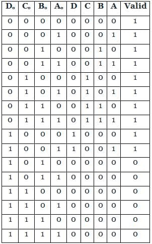
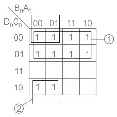
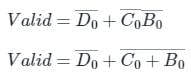
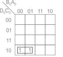
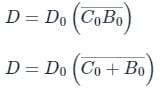
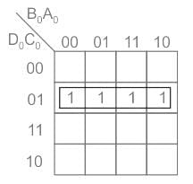
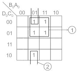
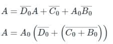
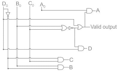
A binary-to-BCD encoder has four inputs D0 C0, B0, and A0 and five outputs D, C, B, A, and VALID. The outputs D, C, B and A give the proper BCD value of the input and the VALID output is 1 if the input combination is a valid decimal code. If the input combination is an invalid decimal code, the VALID output becomes 0, and all of the D, C, B, and A outputs show 0 values. If only NOT gates and 2-input OR and AND gates are available, the minimum number of gates required to implement the above circuit is
Decimal to BCD
BCD is represented with four digits.
The valid decimal numbers for BCD conversion are from 0 to 9 only.
Calculation:
According to the given statement, 4 inputs and 5 outputs are there.
Inputs are D0, C0, B0, A0
Outputs are D, C, B, A, Valid
Logic implementation is shown in the below table
For valid output logic 1 is taken.
The K-map for Valid is
Valid = Σ (0 to 9)
Output equation is
The K-map for D is
Valid = Σ (8, 9)
Output equation is
The K-map for C is
Valid = Σ (4, 5, 6, 7)
Output equation is
The K-map for B is
Valid = Σ (2, 3, 6, 7)
Output equation is
The K-map for A is
Valid = Σ (1, 3, 5, 7, 9)
Output equation is
Implementing the above logic circuit we require 8 minimum gates as shown:
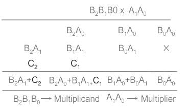
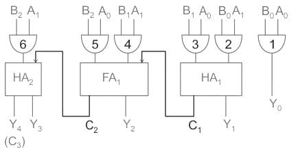
Minimum number of Half adders, Full adders, AND gates required to implement 2 × 3 multiplier is given as
Multiplier
Process
1) The first product obtained from multiplying A0 with the multiplicand is called as partial product 1.
2) And the second product obtained from multiplying A1 with the multiplicand is known as the partial product 2.
The structure of multiplication is explained below
There are 6 product terms so to get all those 6 AND gates are required.
To get the addition of B1A0 and B0A1 we require one-half adder and this produces a carry also.
To get the addition of B2A0, B1A1 and C1 we require Full adder because of 3 inputs and this also produces a carry.
To get the B2A1 and C2 we require one-half adder because of 2 inputs.
Conclusion:
Total 6 AND gates, 2 Half adders and 1 Full adder are required.
Let the input to the circuit be 1010. The circuit is redrawn as:
∴ For an input 1010, we get the output as 1100.
Similarly, let the input be 0110. The circuit is drawn as:
The output for 0110 input is 0100
Observations:
∴ The given circuit converts Gray code to Binary code
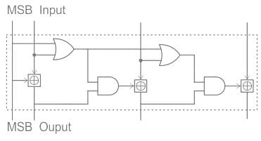
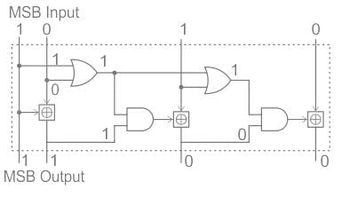
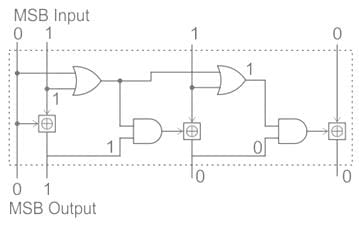
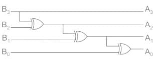
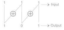
Identify the circuit below.
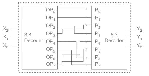
Note: Change in the above connection
OP4 is connected to IP7
OP5 is connected to IP6
Rest connections are same
Concept:
Gray to Binary
Gray codes are widely used to facilitate error correction in digital communications such as digital terrestrial television and some cable TV systems.
Conversion from Gray Code to Binary Code:
Let Gray Code be G3 G2 G1 G0 and Binary Code be B3 B2 B1 B0. Then the respective Grey Code can be obtained as follows:
Binary to Gray
It is given by
y1 = x1
y2 = x1 ⊕ x2
y3 = x2 ⊕ x3
y4 = x3 ⊕ x4
Analysis:
Assume X2X1X0 = (111)2 = 710
Then the output of the first decoder = OP7 which is connected to IP5 of the encoder
(5)10 = (101)2
∴ output of encoder Y2Y1Y0 = 101
∴ input to the circuit = 1 1 1 and output = 1 0 1
Consider Gray to Binary converter if input = 111 then output is 101.
∴ So the given circuit acts like a Gray to Binary converter
Hence option (3) is correct
The reflected binary code is also known as gray code because one digit reflected to the next bit.
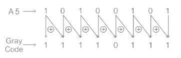
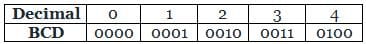
The binary representation of BCD number 00101001 (decimal 29) is
The given BCD number 00101001 has three 1s.
So, it can be rewritten as 0000001-1, 0001000-8, 0010100-20 and after addition, we get 0011101 as output.
Gray code is useful because only one bit changes at a time, which is implemented easily in Coded representation of a shaft’s mechanical position.