Electronics and Communication Engineering (ECE) Exam  >  Electronics and Communication Engineering (ECE) Test  >  GATE ECE (Electronics) Mock Test Series 2027  >  Test: Miller Effect Capacitance - Electronics and Communication Engineering (ECE) MCQ

GATE ECE (Electronics) Test: Miller Effect Capacitance Free Online Test


MCQ Practice Test & Solutions: Test: Miller Effect Capacitance (10 Questions)

You can prepare effectively for Electronics and Communication Engineering (ECE) GATE ECE (Electronics) Mock Test Series 2027 with this dedicated MCQ Practice Test (available with solutions) on the important topic of "Test: Miller Effect Capacitance". These 10 questions have been designed by the experts with the latest curriculum of Electronics and Communication Engineering (ECE) 2026, to help you master the concept.

Test Highlights:

  • - Format: Multiple Choice Questions (MCQ)
  • - Duration: 30 minutes
  • - Number of Questions: 10

Sign up on EduRev for free to attempt this test and track your preparation progress.

Test: Miller Effect Capacitance - Question 1

In Miller’s theorem, what is the constant K?

Detailed Solution: Question 1

The constant K = V2/V1, which is the internal voltage gain of the network.
Thus resistance R= R/1-K
R= R/1-K-1.

Test: Miller Effect Capacitance - Question 2

Find net voltage gain, given hfe = 50 and hie = 1kΩ.
Find net voltage gain if hfe is 50 & hie is 1kΩ by millers theorem to resistance
 

Detailed Solution: Question 2

Apply millers theorem to resistance between input and output.
At input, R= 100k/1-K = RI
Output, R= 100k/1-K-1 ≈ 100k
Internal voltage gain , K = -hfeRL’/hie
K = – 50xRc||100k/1k = – 50x4x100/104 = – 192
RI = 100k/1+192 = 0.51kΩ
RI’ = RI||hie = 0.51k||1k = 0.51×1/1.51 = 0.337kΩ
Net voltage gain = K.RI’/RS+RI’ = – 192 x 0.337/2k + 0.337k = -27.68.

Test: Miller Effect Capacitance - Question 3

Consider an RC coupled amplifier at low frequency. Internal voltage gain is -120. Find the voltage gain magnitude, when given that collector resistance = 1kΩ, load = 9kΩ, collector capacitance is 0. is 0.1μF, and input frequency is 20Hz.

Detailed Solution: Question 3

 AV = -120
fL = 1/2πCC(R+ RL) = 1/2π x 0.001 = 1000/2π = 159.15Hz
AV’ = 120/8.02 ≈ 15.

Test: Miller Effect Capacitance - Question 4

Given collector resistance = 2kΩ, load resistance = 5kΩ, collector capacitance = 1μF, emitter capacitance = 20μF, collector current = 2mA, source resistance = 2kΩ. If the effect of blocking capacitor is ignored, find the applicable cut-off frequency.

Detailed Solution: Question 4

RC = 2kΩ, RL = 5kΩ, CC = 1μF, CB = 10μF, CE = 20μF, RS = 2 kΩ
hie = 1kΩ, IC = 2mA
fL1 = 1/2πCC(RC+RL) = 22.73 Hz
fL2 = gm/2πCE = IC/2πCEVT = 612 Hz
Since fL2 > 4fL1, hence fL2 is the correct answer.

Test: Miller Effect Capacitance - Question 5

What is the phase shift in RC coupled CE amplifier at lower 3dB frequency?

Detailed Solution: Question 5

Total phase shift = 180°+ tan-1(fL/f)
At 3dB frequency fL/f = 1
Total phase shift = 180° + 45° = 225°.

Test: Miller Effect Capacitance - Question 6

When applying miller’s theorem to resistors, resistance R1 is for node 1 and R2 for node 2. If R1>R2, then for same circuit, then for capacitance for which the theorem is applied, which will be larger, C1 or C2?

Detailed Solution: Question 6

Given R1 > R2
R/1-K > R/1-K-1, and so 1-K-1 > 1-K
Thus K2>1, K>1, K<-1 (correct)
Thus, C1 = C(1-K) and C2 = C(1-K-1)
Hence C1>C2.

Test: Miller Effect Capacitance - Question 7

Given that capacitance w.r.t the input node is 2pF and output node is 4pF, find capacitance between input and output node.

Detailed Solution: Question 7

C1 = C(1 - K), C2 = C(1 - K-1)
C1 = 2pF
C2 = 4pF
C1/C2 = 1/2 = 1-K/1-K-1
K = -2
C1 = C(1 + 2) = 3C
C = C1/3 = 2/3pF = 0.67 pF.

Test: Miller Effect Capacitance - Question 8

Find the 3-dB frequency given that the gain of RC coupled amplifier is 150, the low frequency voltage gain is 100 and the input frequency is 50Hz.

Detailed Solution: Question 8

AVM = 150
AVL = 100
f = 50Hz
1 + f2/2500 = 1.52
f2 = 2500*1.25 = 3125
f = 55.90 Hz.

Test: Miller Effect Capacitance - Question 9

Consider the circuit shown.
Find magnitude of voltage gain at input frequency 10Hz if hfe is 50 & hie is 1000Ω
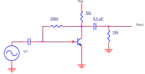
hfe = 50, hie = 1000Ω. Find magnitude of voltage gain at input frequency 10Hz.

Detailed Solution: Question 9

Net load = 10k||10k = 5kΩ = RL
AVM = -hfeRL’/hie = -50 × 5/1 = -250
fL = 1/2πCC(RC+RL) = 15.9 Hz
AVL = 133.

Test: Miller Effect Capacitance - Question 10

Consider that the phase shift of an RC coupled CE amplifier is 260°. Find the low frequency gain when the voltage gain of the transistor is -150.

Detailed Solution: Question 10

180° + tan-1(fL/f) = 260°
fL/f = tan(80) = 5.67
A = 20.3 + 5.672 = 26.05.

26 docs|263 tests
Information about Test: Miller Effect Capacitance Page
In this test you can find the Exam questions for Test: Miller Effect Capacitance solved & explained in the simplest way possible. Besides giving Questions and answers for Test: Miller Effect Capacitance, EduRev gives you an ample number of Online tests for practice
Download as PDF