Electrical Engineering (EE) Exam  >  Electrical Engineering (EE) Tests  >  Test: ESE Electrical - 5 - Electrical Engineering (EE) MCQ

Test: ESE Electrical - 5 - Electrical Engineering (EE) MCQ


Test Description

30 Questions MCQ Test - Test: ESE Electrical - 5

Test: ESE Electrical - 5 for Electrical Engineering (EE) 2025 is part of Electrical Engineering (EE) preparation. The Test: ESE Electrical - 5 questions and answers have been prepared according to the Electrical Engineering (EE) exam syllabus.The Test: ESE Electrical - 5 MCQs are made for Electrical Engineering (EE) 2025 Exam. Find important definitions, questions, notes, meanings, examples, exercises, MCQs and online tests for Test: ESE Electrical - 5 below.
Solutions of Test: ESE Electrical - 5 questions in English are available as part of our course for Electrical Engineering (EE) & Test: ESE Electrical - 5 solutions in Hindi for Electrical Engineering (EE) course. Download more important topics, notes, lectures and mock test series for Electrical Engineering (EE) Exam by signing up for free. Attempt Test: ESE Electrical - 5 | 150 questions in 180 minutes | Mock test for Electrical Engineering (EE) preparation | Free important questions MCQ to study for Electrical Engineering (EE) Exam | Download free PDF with solutions
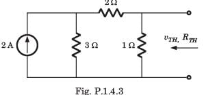
Test: ESE Electrical - 5 - Question 1

vTH, RTH = ?

Detailed Solution for Test: ESE Electrical - 5 - Question 1


Test: ESE Electrical - 5 - Question 2

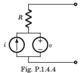
A simple equivalent circuit of the 2 terminal network shown in fig. P1.4.4 is
Detailed Solution for Test: ESE Electrical - 5 - Question 2

After killing all source equivalent resistance is R Open circuit voltage = v1

1 Crore+ students have signed up on EduRev. Have you? Download the App
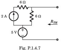
Test: ESE Electrical - 5 - Question 3

RTH = ?

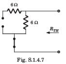
Detailed Solution for Test: ESE Electrical - 5 - Question 3

After killing the source, RTH = 6 Ω

Test: ESE Electrical - 5 - Question 4

In the circuit shown in fig.all initial condition are zero.

If is (t) = 1 A, then the inductor current iL(t) is 

Detailed Solution for Test: ESE Electrical - 5 - Question 4


Test: ESE Electrical - 5 - Question 5

In the circuit shown in fig. all initialcondition are zero

If is(t) = 0.5t A, then iL(t) is

Detailed Solution for Test: ESE Electrical - 5 - Question 5

Trying iL (t)= At+ B,


A = 1, B = 1

Test: ESE Electrical - 5 - Question 6

In the circuit of fig. switch is moved from position a to b at t =  0. The iL(t) for t > 0 is

Detailed Solution for Test: ESE Electrical - 5 - Question 6


α = ωo critically damped
v(t) = 12 + (A + Bt)e-5t
0 = 12 + A, 150 = -5A + B A = -12, B = 90
v(t) =12 + (90t -12)e-5t 
iL(t) = 0.02(-5) e-5t(90t -12) +0.02(90)e-5t = (3 -9t)e-5t

Test: ESE Electrical - 5 - Question 7

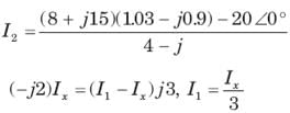
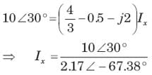
Ix = ?

Detailed Solution for Test: ESE Electrical - 5 - Question 7


Test: ESE Electrical - 5 - Question 8

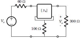
For the 2-port of fig. 


The value of vo/vs is 

Detailed Solution for Test: ESE Electrical - 5 - Question 8


  V1 = 600I1 + 100I2 , V2 = 100I1 + 200I2
Vs = 60I1 + V1 = 660I1 + 100I2 , V2 = Vo = -300I2

Test: ESE Electrical - 5 - Question 9

A 415 V, three-phase star-connected alternator supplies a delta-connected load, each phase of which has an impedance of (86∠54.46°) Ω. Calculate kVA rating of the alternator, neglecting losses in the line between the alternator and load.

Detailed Solution for Test: ESE Electrical - 5 - Question 9

Concept
The kVA rating for a delta-connected load is given by:
S = 3VPIP
where, VP = Phase Voltage
IP = Phase Current
The phase current is given by: IP = VP/ZP
Calculation: 
Given, VP = 415 V
ZP = (86∠54A6°)Ω  
IP = 415 / (86∠54.46)
IP = 4.82 ∠-54.46
S = 3 x 415 x 4.82
S = 6.002 kVA 

Test: ESE Electrical - 5 - Question 10

The three impedances Z1 = 20∠30⁰Ω, Z2 = 40∠60⁰Ω, Z3 = 10∠-90⁰Ω are delta-connected to a 400V, 3 – Ø system. Find the power in the Y phase.

Detailed Solution for Test: ESE Electrical - 5 - Question 10

The term power is defined as the product of square of current and the impedance. So the power in the Y phase = 102 x 20 = 2000W.

Test: ESE Electrical - 5 - Question 11

Two small diameter 10gm dielectric balls can slide freely on a vertical channel. Each carry a negative charge of 1μC. Find the separation between the balls if the lower ball is restrained from moving.

Detailed Solution for Test: ESE Electrical - 5 - Question 11

F = mg = 10 X 10-3 X 9.81 = 9.81 X 10⁻² N.
On calculating r by substituting charges, we get r = 0.3m.

Test: ESE Electrical - 5 - Question 12

A charge of 2 X 10⁻⁷ C is acted upon by a force of 0.1N. Determine the distance to the other charge of 4.5 X 10⁻⁷ C, both the charges are in vacuum.

Detailed Solution for Test: ESE Electrical - 5 - Question 12

F = q1q2/(4∏εor2) , substituting q1, q2 and F, r2 = q1q2/(4∏εoF) =
We get r = 0.09m.

Test: ESE Electrical - 5 - Question 13

A control system transfer function is H(s) = 1/s3. Express its impulse response in terms of unit step signal

Detailed Solution for Test: ESE Electrical - 5 - Question 13

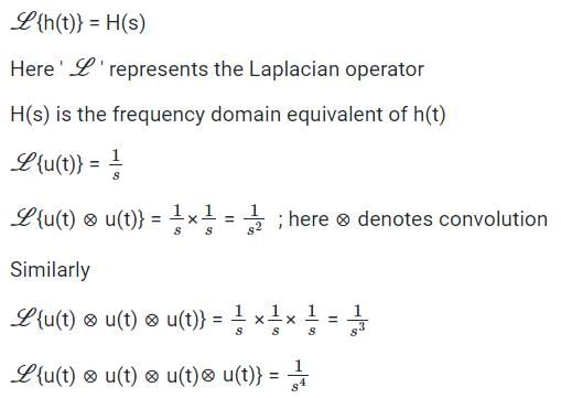
Convolution in the time domain implies multiplication in S(or frequency) domain

The Laplace transform of any signal h(t) is given by

So we observe that the H(s) = 1/s3, corresponds to a unit step signal convoluted with itself thrice.

Therefore the correct answer is option 1

Test: ESE Electrical - 5 - Question 14

Given the z-transforms

The limit of x[ ∞] is

Detailed Solution for Test: ESE Electrical - 5 - Question 14

The function has poles at z = 1,3/4. Thus final value theorem applies.

Test: ESE Electrical - 5 - Question 15

What is the inverse z-transform of X(z)=1/(1-1.5z-1+0.5z-2) if ROC is |z|>1? 

Detailed Solution for Test: ESE Electrical - 5 - Question 15

Since the ROC is the exterior circle, we expect x(n) to be a causal signal. Thus we seek a power series expansion in negative powers of ‘z’. By dividing the numerator of X(z) by its denominator, we obtain the power series

So, we obtain x(n)= {1,3/2,7/4,15/8,31/16,….}.

Test: ESE Electrical - 5 - Question 16

Determine the bilateral laplace transform and choose correct option.


Detailed Solution for Test: ESE Electrical - 5 - Question 16

Test: ESE Electrical - 5 - Question 17

Determine the Laplace transform of given signal.

Detailed Solution for Test: ESE Electrical - 5 - Question 17


Test: ESE Electrical - 5 - Question 18

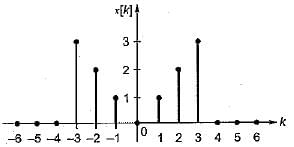
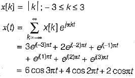
The Fourier series coefficient of time domain signal have been given. Determine the corresponding time domain signal and choose correct option.
Detailed Solution for Test: ESE Electrical - 5 - Question 18

Test: ESE Electrical - 5 - Question 19

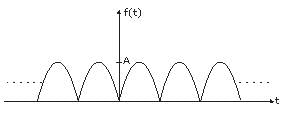
The average value of the periodic waveform shown.

Detailed Solution for Test: ESE Electrical - 5 - Question 19

The average value


Test: ESE Electrical - 5 - Question 20

Determine the Fourier series coefficient for given periodic signal x(t).

x(t) as shown in fig.

​ ​ ​

Detailed Solution for Test: ESE Electrical - 5 - Question 20

Test: ESE Electrical - 5 - Question 21

A continuous-time signal has frequency content at f = 10 MHz, 50 MHz, and 70 MHz. The signal is sampled at a sampling frequency of 56 MHz and is then passed through a low-pass filter with a cutoff frequency of 15 MHz. The frequency content of the output of the filter will be:

Detailed Solution for Test: ESE Electrical - 5 - Question 21

Calculation:
fs = Sampling Frequency = 56 MHz
The frequencies present at the input are:
fm1 = 10 MHz, fm2 = 50 MHz and, fm3 = 70 MHz
Once sampled, the frequency content at the output will be: fm ± fs
For, fm1 = 10 MHz, the output will contain frequencies of,
= fm1, fm1 ±, fm1 ± 2fs ….
= 10 MHz, 66 MHz, 122 MHz
For, fm2 = 50 MHz, the output will contain frequencies of
= fm2, fm2 ± fs, fm2 ± 2fs ….
= 50 MHz, 6 MHz, 106 MHz, 162 MHz
For, fm3 = 70 MHz, the output will contain frequencies of
= fm3, fm3 ± fs, fm3 ± 2fs ….
= 70 MHz, 14 MHz, 182 MHz ….
When these frequencies are passed through a low pass filter with a cutoff frequency of 15 MHz, the only remaining frequencies at its output will be 6MHz, 10 MHz and 14 MHz.

Test: ESE Electrical - 5 - Question 22

How many complex additions are required to be performed in linear filtering of a sequence using FFT algorithm?

Detailed Solution for Test: ESE Electrical - 5 - Question 22

The number of additions to be performed in FFT are Nlog2N. But in linear filtering of a sequence, we calculate DFT which requires Nlog2N complex additions and IDFT requires Nlog2N complex additions. So, the total number of complex additions to be performed in linear filtering of a sequence using FFT algorithm is 2Nlog2N.

Test: ESE Electrical - 5 - Question 23

What is the approximate transition width of main lobe of a Hamming window?

Detailed Solution for Test: ESE Electrical - 5 - Question 23

The transition width of the main lobe in the case of Hamming window is equal to 8π/M where M is the length of the window.

Test: ESE Electrical - 5 - Question 24

What is the Fourier transform of the rectangular window of length M-1?

Detailed Solution for Test: ESE Electrical - 5 - Question 24

We know that the Fourier transform of a function w(n) is defined as

For a rectangular window, w(n)=1 for n=0,1,2….M-1
Thus we get

Test: ESE Electrical - 5 - Question 25

In the system shown in figure below, the sensitivity of the closed loop transfer function w.r.t. parameter a is

Detailed Solution for Test: ESE Electrical - 5 - Question 25

The closed loop transfer function is given by

∴ 
Now,   

∴ 

Test: ESE Electrical - 5 - Question 26

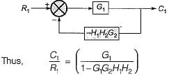
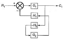
The value of for the system described by the block diagram shown in figure below Is.
Detailed Solution for Test: ESE Electrical - 5 - Question 26

The given block diagram can be reduced as shown below.

Test: ESE Electrical - 5 - Question 27

A linear second-order system with the transfer function G(s) =  is initially at rest and is subjected to a step input signal.
The response of the system will exhibit a peak overshoot of

Detailed Solution for Test: ESE Electrical - 5 - Question 27


Since ξ > 1, therefore the system is overdamped. Hence, there will be no peak overshoot in the output response of the system.

Test: ESE Electrical - 5 - Question 28

Which one of the following is not a property of the Liapunov function?

Detailed Solution for Test: ESE Electrical - 5 - Question 28

To determine which of the given properties is not true for a Liapunov function, let's analyze each option:

A: It is a unique function for a given system. This statement is true. A Liapunov function is unique for a given system. If there were multiple Liapunov functions for the same system, it would imply different stability properties, which would contradict the definition of a Liapunov function.

B: It is positive definite, at least in the neighborhood of the origin. This statement is generally true. A Liapunov function must be positive definite in a neighborhood of the origin, meaning it is greater than zero for all points other than the origin within a certain distance. This condition ensures that the function is decreasing towards the equilibrium point.

C: It is a scalar function. This statement is true. A Liapunov function is a scalar function, meaning it takes a single value for each point in the system's state space.

D: Its time derivative is non-positive. This statement is also true. The time derivative of a Liapunov function must be non-positive for all points within the system's state space, except at the origin. This condition guarantees that the function is decreasing along the system's trajectories towards the equilibrium point.

Therefore, the property that is not true for a Liapunov function is option A: It is not a unique function for a given system.

Test: ESE Electrical - 5 - Question 29

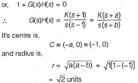
The root locus of s(s - 1) + K(s + 1) = 0 is a circle. The co-ordinates of the centre and the radius (in units) of this circle are respectively

Detailed Solution for Test: ESE Electrical - 5 - Question 29

Given, s(s - 1) + K(s + 1) = 0 

Test: ESE Electrical - 5 - Question 30

A system with phase margin close to zero or gain margin close to unity is 

Detailed Solution for Test: ESE Electrical - 5 - Question 30

The correct answer is D: relatively stable.

In control systems, the phase margin and gain margin are measures of the system's stability and robustness. The phase margin represents the amount of phase lag the system can tolerate before it becomes unstable, while the gain margin indicates how much additional gain the system can handle before instability occurs.

When the phase margin is close to zero or the gain margin is close to unity, it implies that the system is operating near the stability limits. However, it does not necessarily mean that the system is completely unstable or highly unstable.

Option A: unstable is incorrect because a system with a phase margin close to zero or gain margin close to unity is not necessarily unstable. It indicates that the system is close to the stability boundary but can still exhibit stability if the margins are slightly positive or slightly below unity.

Option B: highly stable is incorrect because operating near the stability limits does not necessarily imply higher stability. It suggests that the system is more susceptible to instability if there are any disturbances or changes in the system parameters.

Option C: oscillatory is incorrect because the phase margin and gain margin do not directly indicate oscillatory behavior. Oscillations depend on other factors like the system's poles and zeros.

Option D: relatively stable is the most appropriate answer. When the phase margin is close to zero or the gain margin is close to unity, it indicates that the system is relatively stable but operating near its stability limits. It suggests that the system is more sensitive to disturbances and parameter variations, making it less robust compared to systems with larger margins.
View more questions
Information about Test: ESE Electrical - 5 Page
In this test you can find the Exam questions for Test: ESE Electrical - 5 solved & explained in the simplest way possible. Besides giving Questions and answers for Test: ESE Electrical - 5, EduRev gives you an ample number of Online tests for practice

Top Courses for Electrical Engineering (EE)

Download as PDF

Top Courses for Electrical Engineering (EE)