Capacitance MCQ Level - 1 - Class 12 MCQ
30 Questions MCQ Test - Capacitance MCQ Level - 1
A parallel plate capacitor has circular plates of 10 cm radius separated by an air-gap of 1 mm. It is charged by connecting the plates to a 100 volt battery. Then the change in energy stored in the capacitor when the plates are moved to a distance of 1 cm and the plates are maintained in connection with the battery is:
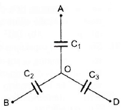
Three uncharged capacitors of capacitance C1, C2 and C3 are connected as shown in figure to one another and to points A, B and D at potentials VA, VB and VD. Then the potential at O will be:

| 1 Crore+ students have signed up on EduRev. Have you? Download the App |
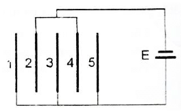
Five identical capacitor plates, each of area A, are arranged such that the adjacent plates are at a distance d apart. The plates are connected to a battery of emf E volt as shown. The charges on plates 1 and 4 respectively are:

Two spherical conductors of radii 2 cm and 6 cm are placed concentrically in air. The inner sphere is connected to earth while the other is given a charge of +9 statcoulomb. Then the charge in statcoulomb on the inner sphere is:
Suppose n identical capacitors are joined in parallel and charged to potential V. Now, they are separated and joined in series. If the energy possessed by each capacitor is U, then on joining them in series, the energy and potential difference for the combination are:
A capacitor of capacitance C1 is charged to a potential V0. The electrostatic energy stored in it is U0. It is connected to another uncharged capacitor of capacitance C2 in parallel. The energy dissipated in the process is:
Minimum number of 8μF and 250 V capacitors used to make a combination of 16μF and 1000 V are :
In the given figure, the capacitors C1, C3, C4 and C5 have a capacitance of 4μF each. If the capacitor C2 has a capacitance of 10μF, then the effective capacitance between A and B is :
A capacitor of capacity 10 μF is charged to 40 volt and a second capacitor of capacity 16 μF is charged to 30 volt. If they are connected in parallel the amount of charge that flows from the smaller capacitor to the higher capacitor (in μC) is
A thin metal plate P is inserted half-way between the plates of a parallel plate capacitor of capacitance C in such a way that it is parallel to the two plates. The capacitance now becomes:
A parallel plate capacitor has plate area A and separation d. It is charged to a potential difference V0. The charging battery is disconnected and the plates are pulled apart to three times the initial separation. The work required to separate the plates is:
In the circuit shown in the figure, C = 6 μF. The charge stored in the capacitor of capacity C is:
One plate of a capacitor is connected fo a spring as shown in the figure. Area of both the plates is A. In steady state separation between the plates is 0.8d (spring was unstretched and the distance between the plates was d when the capacitor was uncharged). The force constant of the spring is approximately:
Capacity of an isolated sphere is increased n times when it is enclosed by an earthed concentric sphere. The ratio of their radii is:
Three conducting spheres A, B and are as shown in the figure. The radii of the spheres are a, b and c respectively. A and B are connected by a conducting wire. The capacity of the system is:
The metal plate on the left in the figure carries a charge + q. The metal plate on the right has a charge of -2q. What charge will flow through S when it is closed if the central plate is initially neutral?
Two identical capacitors 1 and 2 are connected in series to a battery as shown in the figure. Capacitor 2 contains a dielectric slab of dielectric constant K as shown. Q1 and Q2 are the charges stored in the capacitors. Now, the dielectric slab is removed and the corresponding charges are Q'1 and Q'2. Then:
An insulator plate is passed between the plates of a capacitor. Then current:
Between the plates of a parallel plate capacitor of capacity C, two parallel plates, of the same material and area same as the plate of the original capacitor, are placed. If the thickness of these plates is equal to (1/5)th of the distance between the plates of the original capacitor, then the capacity of the new capacitor is:
A parallel plate capacitor C0 is charged to a potential V0.The energy stored in the capacitor when the battery is disconnected and the plate separation is doubled is E1. The energy stored in the capacitor when the charging battery is kept connected and the separation between he capacitor plates is doubled is E2. Then E1/E2 is:
A sheet of aluminium foil of negligible thickness is introduced between the plates of a capacitor. The capacitance of the capacitor:
A spherical drop of capacitance 1μF is broken into eight drops of equal radius. The radius of each small drop is:
All the six capacitors shown in the circuit are identical. Each can withstand maximum 200 volt between its terminals. The maximum voltage that can be applied safely between A and B is :
In the circuit shown, a potential differnce of 60 V is applied across AB. The potential difference between the points M and N is :
Three very large plates are given charges as shown in the figure. If the cross-sectional area of each plate is the same, the final charge distribution on plate C is:
The expression for the equivalent capacitance of the system shown is: (A is the cross-sectional area of one of the plates)
A fully charged capacitor has a capacitance C. It is discharged through a small coil of resistance wire embedded in a thermally insulated block of specific heat capacity s and mass m. If the temperature of the block is raised by ΔT , the potential difference V across the capacitance is:
A network of four capacitors of capacity equal to C1 = C, C2 = 2C, C3 = 3C and C4 = 4C are connected to a battery as shown in the figure. The ratio of the charges on C2 and C4 is:
Five capacitors each of capacitance value C are connected as shown in the figure.The ratio of capacitance between P and R and the capacitance between P and Q is:
A network of six identical capacitors, each of value C, is made as shown in the figure. The equivalent capacitance between the points A and B is :


