Current MCQ Level - 1 Class 12 MCQs & solutions - Free
MCQ Practice Test & Solutions: Current MCQ Level - 1 (40 Questions)
You can prepare effectively for Class 12 with this dedicated MCQ Practice Test (available with solutions) on the important topic of "Current MCQ Level - 1". These 40 questions have been designed by the experts with the latest curriculum of Class 12 2026, to help you master the concept.
Test Highlights:
- - Format: Multiple Choice Questions (MCQ)
- - Duration: 80 minutes
- - Number of Questions: 40
Sign up on EduRev for free to attempt this test and track your preparation progress.

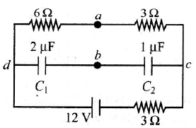
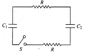
What is the charge stored on each capacitor C1 and C2 in the circuit shown below?
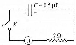
A charged capacitor is allowed to discharge through a resistorby closing the key at the instant t = 0 (see fig). At the instant t = (In 4) μs, the reading of the ammeter falls half the initial value. The resistance of the ammeter is equal to

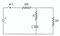
In the circuit shown in Fig. switch S is closed at time t = 0, Let l1 and l2 be the currents at any finite time t, then the ratio I1 / I2.
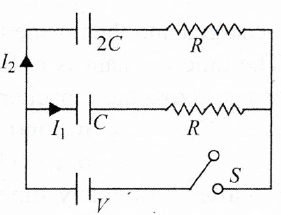
In the circuit shown in fig. C1 = 2C2. Initially, capacitor C1 is charged to a potential of V. The current in the circuit just after the switch S is closed is
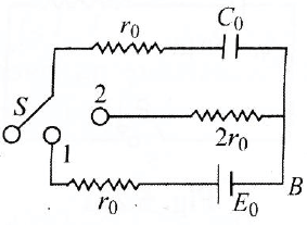
ln the circuit given in Fig. switch S is at position 1 for long time. Find the total heat generated in resistor of resistance (2r), when the switch S is shifted from 1 to position 2.
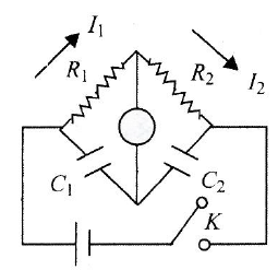
In the circuit in Fig., if no current flows through the galvanometer when the key k is closed, the bridge is balanced. The balancing condition for bridge is
A capacitor of capacitance C has charge Q. It is connected to an identical capacitor through a resistance. The heat produced in the resistance is:
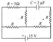
In the circuit shown in Fig. the cell is ideal with e.m.f = 15 V. Each resistance is of 3  . The potential difference across the capacitor in steady state is:
. The potential difference across the capacitor in steady state is:A straight conductor of uniform cross section carries a time varying current which varies at the rate  If s is the specific charge that is carried by each charge carrier of the conductor and l is the length of the conductor, then the total force experienced by all the charge carriers per unit length of the conductor due to their drift velocities only is
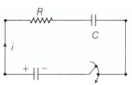
If s is the specific charge that is carried by each charge carrier of the conductor and l is the length of the conductor, then the total force experienced by all the charge carriers per unit length of the conductor due to their drift velocities only isA capacitor is charged to a certain potential and then allowed to discharge through a resistance R. The ratio of charge on the capacitor to current in the circuit
Two capacitor C1 and C2 (C1 > C2) are charged separately to same potential. Now they are allowed to discharge through similar resistors. Initial rate of discharging will be
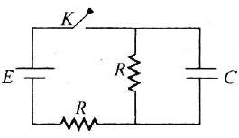
In the circuit shown in the diagram, E is the e.m.f of the cell, connected to two resistances, each of magnitude R and a capacitor of capacitance C as shown in the diagram. If the switch key K is connected at time t = 0, the growth of potential V across the capacitor will be correctly given by
The plates of capacitor are charged to a potential difference of 320 V and then connected across a resistor. If potential difference between plates of capacitor becomes 240 V after 1 s, then potential difference after 2 and 3 s will be
A 4 μF capacitor and a resistance of 2.5 x 10⁶ are connected in series with a battery of 12 V. Time after which potential difference across the capacitor is 3 times of potential difference across the resistor is
are connected in series with a battery of 12 V. Time after which potential difference across the capacitor is 3 times of potential difference across the resistor isA capacitor is charged steadily from a DC source. Correct variation of potential difference across the plates of capacitor with charge on the plates of capacitor is:
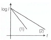
A capacitor is made to discharge across a pure resistor. A plot of log I versus t (l = instantaneous current and t = instantaneous time) is recorded as shown in graph 1. The same experiment is repeated with a change and graph 2 is observed. Then,
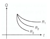
Three identical capacitors are charged by connecting them in parallel across a battery of V volt. They are then allowed to discharge via resistor R1, R2 and R3. Here, Q charge versus t time graphs are shown. Then,
For the circuit shown in figure below, At t = 0, switch is closed, the initial current through resistor and final charge on capacitor are
For the given circuit shown in figure below, Time constant is
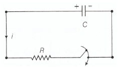
During charging of capacitor in the circuit shown,
Circuit current versus time graph is
During discharging of a capacitor via a resistor
Circuit current versus with time as
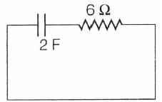
In a capacitor shown in the circuit is charged to 5V and left in the circuit in 12 S. The charge on the capacitor will becomes
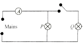
How will the reading in the ammeter A of Fig. be affected if another identical bulb Q is connected in parallel to P as shown. The voltage in the mains is maintained at a constant value.
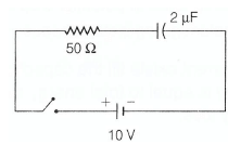
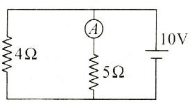
In the circuit shown in Fig., the reading of the ammeter is (assume internal resistance of the battery be to zero)
In the circuit shown in Fig. resistors Xand Y, each with resistance R are connected to a 6V battery of negligible internal resistance. A voltmeter, also of resistance R, is connected across Y.
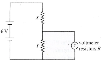
What is the reading of the voltmeter?
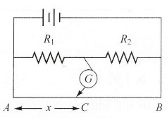
In the shown arrangement of the experiment of a meter bridge, if AC corresponding to null deflection of galvanometer is x, what would be its value if the radius of the wire AB is doubled?
The length of a wire of a potentiometer is 100 cm, and the e.m.f. of its standard cell is E volt. It is employed to measure the e.m.f. of a battery whose internal resistance is 0.5 . If the balance point is obtained at  = 30 cm from the positive end, e.m.f. of the battery is
. If the balance point is obtained at = 30 cm from the positive end, e.m.f. of the battery isIn a metre bridge experiment, null point is obtained at 20 cm from one end of the wire when resistance X is balanced against another resistance Y. If X < Y, then where will be the new position of the null point from the same end, if one decides to balance a resistance of 4X against Y?
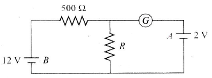
In the circuit shown in Fig., the galvanometer G shows zero deflection. If the batteries A and B have negligible internal resistance, the value of the resistor R will be