Electrical Engineering (EE) Exam  >  Electrical Engineering (EE) Tests  >  Test: Digital Electronics- 1 - Electrical Engineering (EE) MCQ

Test: Digital Electronics- 1 - Electrical Engineering (EE) MCQ


Test Description

15 Questions MCQ Test - Test: Digital Electronics- 1

Test: Digital Electronics- 1 for Electrical Engineering (EE) 2024 is part of Electrical Engineering (EE) preparation. The Test: Digital Electronics- 1 questions and answers have been prepared according to the Electrical Engineering (EE) exam syllabus.The Test: Digital Electronics- 1 MCQs are made for Electrical Engineering (EE) 2024 Exam. Find important definitions, questions, notes, meanings, examples, exercises, MCQs and online tests for Test: Digital Electronics- 1 below.
Solutions of Test: Digital Electronics- 1 questions in English are available as part of our course for Electrical Engineering (EE) & Test: Digital Electronics- 1 solutions in Hindi for Electrical Engineering (EE) course. Download more important topics, notes, lectures and mock test series for Electrical Engineering (EE) Exam by signing up for free. Attempt Test: Digital Electronics- 1 | 15 questions in 45 minutes | Mock test for Electrical Engineering (EE) preparation | Free important questions MCQ to study for Electrical Engineering (EE) Exam | Download free PDF with solutions
Test: Digital Electronics- 1 - Question 1

What are the essential prime implicants of following Boolean function x'z + y`z + xz'

Detailed Solution for Test: Digital Electronics- 1 - Question 1

flx, y, z)= xlz + ylz + xzl These pairs are essential

Test: Digital Electronics- 1 - Question 2

Consider a multiplexer with X &Y as data inputs and z as a control pin. If Z = 0, selects input X and Z = I , selects input Y what are the connections required to realize the 2 - variable Boolean functions f T R

Detailed Solution for Test: Digital Electronics- 1 - Question 2

1 Crore+ students have signed up on EduRev. Have you? Download the App
Test: Digital Electronics- 1 - Question 3

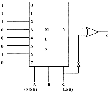
A combinational circuit, using 8 x 1 MUX is shown in figure. The minimized expression for output Z is
Detailed Solution for Test: Digital Electronics- 1 - Question 3


Test: Digital Electronics- 1 - Question 4

The Minimal Product of sums function described by k-Map, shown in figure is

Detailed Solution for Test: Digital Electronics- 1 - Question 4

Test: Digital Electronics- 1 - Question 5

The output of an AND gate with three inputs, A, B, and C, is HIGH when ________.

Test: Digital Electronics- 1 - Question 6

The digital circuit using two inverters shown in figure will acts as

Detailed Solution for Test: Digital Electronics- 1 - Question 6

When 2 inverters are connected then it will become bi-stable.

Test: Digital Electronics- 1 - Question 7

Why is a demultiplexer called a data distributor? 

Detailed Solution for Test: Digital Electronics- 1 - Question 7

A demultiplexer sends a single input to multiple outputs, depending on the select lines. For one input, the demultiplexer gives several outputs. That is why it is called a data distributor.

*Answer can only contain numeric values
Test: Digital Electronics- 1 - Question 8

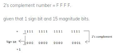
If 2's complement representation of a 16-bit number (one-sign bit and 15 Magnitude bits) is FFFFthen its magnitude in decimal representation is ____


Detailed Solution for Test: Digital Electronics- 1 - Question 8

Test: Digital Electronics- 1 - Question 9

The initial state of MOD — 16, down counter is 0110. What state will be it be after 37 clock pulses??

Detailed Solution for Test: Digital Electronics- 1 - Question 9


Test: Digital Electronics- 1 - Question 10

In the given figure shows a negative logic AND gate. If positive logic is used this gate is equivalent to

Detailed Solution for Test: Digital Electronics- 1 - Question 10

The symbol itself is that of an AND gate; however, due to the presence of the circle (indicating inversion), it is a Negative-Logic AND gate. This means that when using positive logic (where a high voltage represents a logical '1' and a low voltage represents a logical '0'), the gate behaves oppositely to its symbol.

So, if we convert this negative-logic AND gate into an equivalent positive-logic gate, the inversion circle at the output negates the AND operation, effectively turning it into a NOR gate.

Therefore, the correct answer to the question in the image would be:

2. NOR gate

This is because the NOR gate is the positive-logic equivalent of a negative-logic AND gate.

Test: Digital Electronics- 1 - Question 11

An 8085 Microprocessor based system uses a 4 k x 8 bit RAM whose starting address is AAOOH. The address of last byte in this RAM is

Detailed Solution for Test: Digital Electronics- 1 - Question 11

4K x 8 = 212 x 8 bit it has 12 bits So address of last - byte will be AA 00 + 0 FFF = B9FF

Test: Digital Electronics- 1 - Question 12

What is F's complement of (2BFD)16

Detailed Solution for Test: Digital Electronics- 1 - Question 12

F'S complement of 2BFD is FFF F - 2BFD = D402

Test: Digital Electronics- 1 - Question 13

A. ROM is interfaced to an 8085 CPU as indicated in figure, shown, what is address range occupied by ROM is

Detailed Solution for Test: Digital Electronics- 1 - Question 13

A15 A 14 A 13 will be 000 So Range will be

Test: Digital Electronics- 1 - Question 14

112 4-bit 2's complement no's 1011 and 0110 are added, then result expressed in 2's complementnotation is

Test: Digital Electronics- 1 - Question 15

Which one of the following statement is correct?

Information about Test: Digital Electronics- 1 Page
In this test you can find the Exam questions for Test: Digital Electronics- 1 solved & explained in the simplest way possible. Besides giving Questions and answers for Test: Digital Electronics- 1, EduRev gives you an ample number of Online tests for practice

Top Courses for Electrical Engineering (EE)

Download as PDF

Top Courses for Electrical Engineering (EE)