Mechanical Engineering Exam  >  Mechanical Engineering Tests  >  ESE (ME) Paper II Mock Test - 1 - Mechanical Engineering MCQ

ESE (ME) Paper II Mock Test - 1 - Mechanical Engineering MCQ


Test Description

30 Questions MCQ Test - ESE (ME) Paper II Mock Test - 1

ESE (ME) Paper II Mock Test - 1 for Mechanical Engineering 2024 is part of Mechanical Engineering preparation. The ESE (ME) Paper II Mock Test - 1 questions and answers have been prepared according to the Mechanical Engineering exam syllabus.The ESE (ME) Paper II Mock Test - 1 MCQs are made for Mechanical Engineering 2024 Exam. Find important definitions, questions, notes, meanings, examples, exercises, MCQs and online tests for ESE (ME) Paper II Mock Test - 1 below.
Solutions of ESE (ME) Paper II Mock Test - 1 questions in English are available as part of our course for Mechanical Engineering & ESE (ME) Paper II Mock Test - 1 solutions in Hindi for Mechanical Engineering course. Download more important topics, notes, lectures and mock test series for Mechanical Engineering Exam by signing up for free. Attempt ESE (ME) Paper II Mock Test - 1 | 150 questions in 180 minutes | Mock test for Mechanical Engineering preparation | Free important questions MCQ to study for Mechanical Engineering Exam | Download free PDF with solutions
ESE (ME) Paper II Mock Test - 1 - Question 1

What is the drop-in enthalpy (in kJ/kg) for a steam whistle which is perfectly insulated and does not work, has an exit velocity of steam at 40 m/sec?

Detailed Solution for ESE (ME) Paper II Mock Test - 1 - Question 1

Concept:
According to Steady Flow Energy Equation
:
At 1 (steam enters the whistle) and 2 (steam leaves the whistle)


Calculation:
As initial velocity is not given so V1 = 0 and No change in elevation (z1 = z2)
Q = 0 (perfectly insulated)
W = 0 (No work transfer)

ESE (ME) Paper II Mock Test - 1 - Question 2

In a steam power plant, steam flows over the blades of an adiabatic steady flow turbine. The enthalpy at entrance was found to be 4145 kJ/kg and that at exit was 2750 kJ/kg. If the value of flow availability at entrance and exit is 1800 kJ/kg and 150 kJ/kg respectively and dead state temperature is 300 K, then calculate the change of entropy of steam in kJ/kgK. (Neglect kinetic and potential energy)

Detailed Solution for ESE (ME) Paper II Mock Test - 1 - Question 2

Concept:
Given, change in kinetic and potential energy is zero
Therefore, Actual work/kg of steam
Q – W = m(∆h + ∆KE + ∆PE)
Since, turbine is adiabatic so Q = 0
Irreversibility = T0 Sgen = Wmax - Wactual
Wmax = ∅1 - ∅2
where, ∅ = flow availability\
Calculation:
Hence, W = – ∆h = h1 – h2 = 4145 – 2750 = 1395 kJ/kg
Maximum possible work = 1800 – 150 = 1650 kJ/kg
Irreversibility = Max work – actual work = 1650 – 1395 = 255 kJ/kg
T0 Sgen = 255
Sgen = 255/300 = 0.85 kJ/kgK

1 Crore+ students have signed up on EduRev. Have you? Download the App
ESE (ME) Paper II Mock Test - 1 - Question 3

The engine of a Lexus car has three cylinders with a total displacement of 770 cc. If the compression ratio is 8.7, then each cylinder has a clearance volume of

Detailed Solution for ESE (ME) Paper II Mock Test - 1 - Question 3

Concept:
Compression ratio:
Compression ratio is given by the ratio of volume before compression to volume after compression.
​Compression ratio(r) = V1/V2 = Vc + Vs/Vc
[NOTE:
Vc and Vs are clearance and swept volume of single-cylinder only.]
Calculation:
Given:
Total displacement volume = 770 cc, Compression ratio r = 8.7, Number of cylinders = 3

Displacement or swept volume of one cylinder =
∴ Swept volume (one cylinder) = 770/3 = 256.66 cc
​Compression ratio(r) = Vc + Vs/Vc
8.7 = Vc + 256.66/Vc
∴ Vc = 33.246 cc

ESE (ME) Paper II Mock Test - 1 - Question 4

Consider the following statements regarding tidal power generation,

1) Prediction of tides is easy

2) Power generation from tides is free from pollution

3) Tidal energy can be utilized throughout the day

4) Corrosion is a major problem

Which of the above statements are true?

Detailed Solution for ESE (ME) Paper II Mock Test - 1 - Question 4

Concept:

Principle of Tidal Power Generation:

  • Tidal Energy is renewable energy. It is a form of hydro energy recurring with every tide.
  • Tidal energy is converted into mechanical energy by hydro turbines.
  • The difference in the level of ocean water between high tide and low tide results in the ocean's tidal energy.
  • The difference in potential energy during high tide and low tide is tidal energy.


Advantages of Tidal Power Generation:

  • A large area of land is not required
  • Power generation from tides is free from pollution as it does not use any fuel
  • Peak power demand can be effectively met when a tidal power plant works in combination with the hydroelectric or thermal systems.
  • It is an inexhaustible source of energy
  • Prediction of tides is easy
  • The maintenance cost of the tidal plants is less.


Disadvantages of Tidal Power Generation:

  • Tidal energy can only be harnessed in places where a significant change in water level is always available
  • The tidal energy can be utilized for only 10 hours a day
  • The main drawback of tidal energy is that the output varies with the variation in the tidal range.
  • Tidal energy can be utilized only at natural sites
  • Tidal power plants have a very high capital cost
  • The machinery gets corroded due to the corrosiveness of seawater
ESE (ME) Paper II Mock Test - 1 - Question 5

A solar cell with a surface of square cross section has a conversion efficiency 10% and is found to have an open circuit voltage of 0.5 V and a short circuit current of 0.8 A. The beam radiation on the surface is 800 W/m2 and diffused radiation is 10% of the beam. If the fill factor is 0.8, the side of the solar cell will be

Detailed Solution for ESE (ME) Paper II Mock Test - 1 - Question 5

Concept:
The efficiency of Solar cell:

The conversion efficiency is the most commonly used parameter to compare the performance of one solar cell to another. Efficiency is defined as the ratio of energy output from the solar cell to input energy from the sun.
The efficiency of a solar cell is determined as the fraction of incident power which is converted to electricity and is defined as:

Where:
Voc is the open-circuit voltage; Isc is the short-circuit current; FF is the fill factor and η is the efficiency.
G is the irradiation per unit surface area; AS is the area of the solar cell.
Total radiation = Beam radiation + Diffused radiation;
Calculation:

Given ISC = 0.8 A; VOC = 0.5 V; FF = 0.8; η = 10%; Ib = 800 W/m2; Id = 0.1 Ib;
Now the total radiation = 800 (1 + 0.1) = 880 W/m2;
From the efficiency formula,

⇒ As = 3.63 × 10⁻³ m2;
Lets assume the side of square be 'a';
⇒ a2 = 3.63 × 10⁻³ m2;
⇒ a = 0.060 m = 6 cm;

ESE (ME) Paper II Mock Test - 1 - Question 6

A crate of mass 100 kg is at rest on a horizontal floor. The coefficient of static friction between the crate and the floor is 0.4, and the coefficient of kinetic friction is 0.3. A force F of magnitude 344 N is then applied to the crate, parallel to the floor. Which of the following is true?

Detailed Solution for ESE (ME) Paper II Mock Test - 1 - Question 6

Concept:

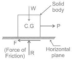
  • As the force is applied to the body the friction force acts on the body which will be opposite to the applied force.
  • As the value of P is going on increasing, at some stage the solid body will be on the verge of motion.
  • The friction force corresponding to this stage is called the limiting force of friction.


The frictional force is given by fL = μN; where N is normal force.
If P > fL, then the frictional force acting will be fL;
If P < fL, then the frictional force acting will be P;
If the body is at rest, frictional force = μs N
If the body is in motion, frictional force = μk N
Calculation:
Given m = 100 kg, μs = 0.4, μk = 0.3, P = 344 N;
Now the limiting frictional force will be
fL = μN = 0.4 × 100 × 9.81 = 392.4 N;
Here P < fL,
Therefore frictional force acting will be P = 344 N;
Since P < fL, the crate will not move

ESE (ME) Paper II Mock Test - 1 - Question 7

On the completion of heat treatment, If the martensite formation finishing temperature is below the room temperature, then which of the following statements is true.

Detailed Solution for ESE (ME) Paper II Mock Test - 1 - Question 7
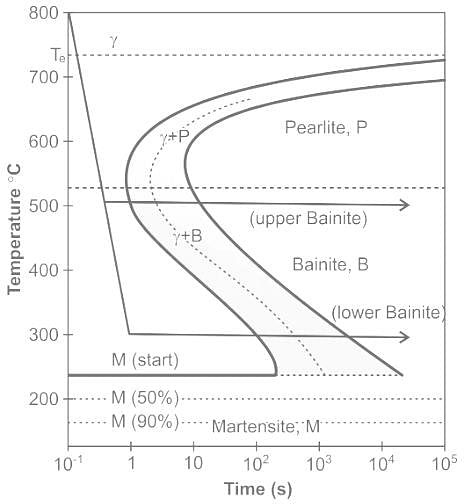
  • Isothermal Transformation diagram or the C-curve is associated with mechanical properties, microconstituents/microstructures, and heat treatments in carbon steels
  • The time-dependent phase transformation (TTT) diagram is given as below, Diffusional transformations like austenite transforming to a cementite and ferrite mixture can be explained with the TTT diagram.​

  • Referring to this TTT diagram, if the martensite finishing temperature is below room temperature, the martensite formation will not complete. This causes the structure to retain austenite after the heat treatment.
ESE (ME) Paper II Mock Test - 1 - Question 8

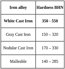
The variety of cast iron which has maximum hardness is

Detailed Solution for ESE (ME) Paper II Mock Test - 1 - Question 8
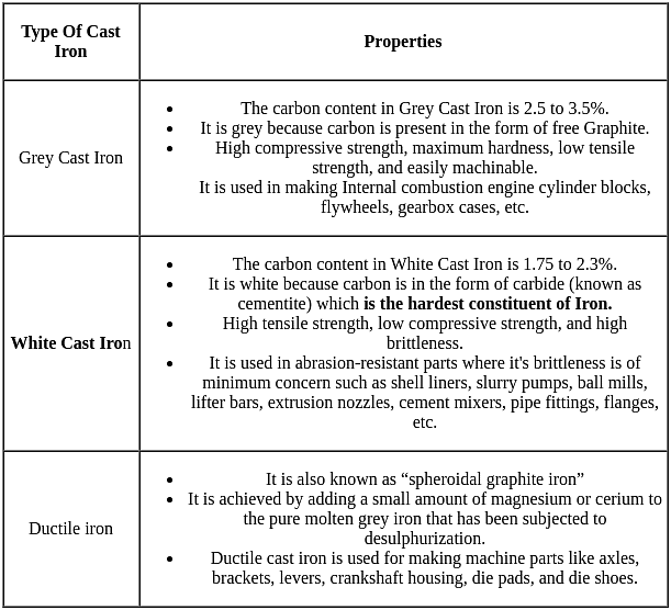
  • Cast iron is primarily an alloy of iron and carbon. The carbon content in cast iron varies from 1.5 to 4 per cent.
  • Small amounts of silicon, manganese, sulphur and phosphorus are also present in it.
  • Carbon in cast iron is present either in a free state like graphite or in combined state as cementite.

ESE (ME) Paper II Mock Test - 1 - Question 9

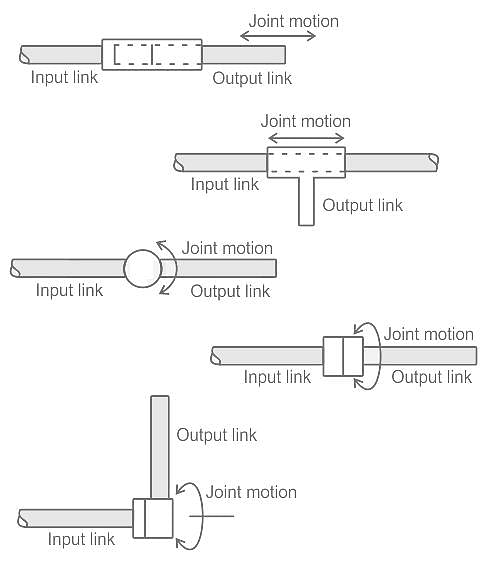
In which of the following type of robotic joint motion the angle between the two links connected changes after rotation/translation?

Detailed Solution for ESE (ME) Paper II Mock Test - 1 - Question 9

Concept:
Manipulator joints in robots are given below,
Translational
motion:

Linear joint (L)Orthogonal joint (O)
Rotary motion:
Rotational joint (R)
Twisting joint (T)
Rotary joint (V)
All the diagrams are given in the order of the names mentioned above.


From the above diagrams, it is clear that the angle between the input link axis and the output link axis
changes only in the Rotational Joint (R).

In the twisting joint (T), both the axes are collinear all the time.
In the Rotary joint (V), both the axes are always perpendicualr.
In the orthogonal joint (O), the angle between them is always 90°.

ESE (ME) Paper II Mock Test - 1 - Question 10

Consider the following statements regarding kinematic pairs:
1. When a pair has a point or line contact between the links, it is known as lower pair.
2. When the elements of a pair are held together mechanically, it is known as closed pair.
3. If two mating links have a turning as well as sliding motion between them, they form a screw pair.
4. When two links of a pair are in contact either due to force of gravity, they constitute an unclosed pair.
Which of the above statements are correct?

Detailed Solution for ESE (ME) Paper II Mock Test - 1 - Question 10

Kinematic pair:

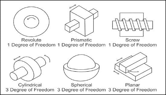
  • The two links of a machine, when in contact with each other, are said to form a pair.
  • A kinematic pair consists of two links that have relative motion between them.
  • The links of a mechanism must be connected together in such a manner that these transmit motion from the driver or input link to the follower or output link.
  • Two elements or links which are connected or joined together in such a way that their relative motion is completely constrained forms a kinematic pair.

kinematic pairs can be classified according to:

  • nature of contact
  • nature of mechanical constraint
  • nature of relative motion

Kinematic pairs according to nature of contact:
Lower pair:

  • When the two elements have surface or area contact while in motion and the relative motion is purely turning or sliding, they are called as lower pair. all sliding pairs, turning pairs and screw pairs are lower pairs. Examples: Nut turning on a Screw, shaft rotating in a bearing, all pairs of a slider crank mechanism, universal joint, etc.

Higher pair:

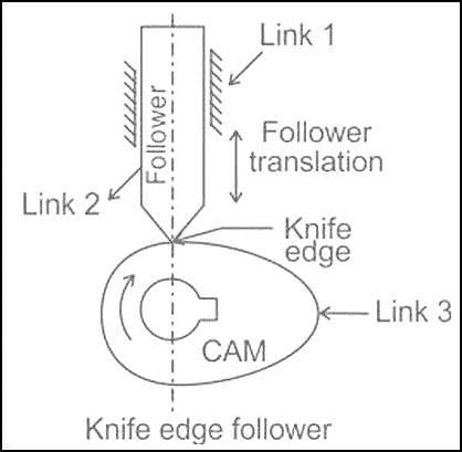
  • A pair of links having a point or line contact between the members is called the higher pair. the contact surfaces of the two links are dissimilar. Examples: contact between cam and follower, contact between two mating gears, A wheel rolling on a rail, ball rolling on a flat surface, ball and roller bearings.

Kinematic pair according to the relative motion:
Sliding pair:

  • If two links have a sliding motion relative to each other, they form a sliding pair. Examples: rectangular rod in a rectangular hole In a prism, Piston and cylinder of an engine, crosshead and Guides of a steam engine, Ram and its guide in shaper, etc.

Turning or revolute pair:

  • When one link has a turning or revolving motion relative to the other, they constitute a turning or revolving pair. Examples: four bar chain, Crankshaft turning in a bearing, etc.

Rolling pair:

  • When the links of a pair have a rolling motion relative to each other, they form a rolling pair. Examples: Ball and roller bearings, wheel rolling on flat surface, etc.

Screw pair ( helical pair):

  • If two mating links have a turning as well as sliding motion between them, they form a screw pair. Examples: Bolt with a nut, lead screw and nut of a lathe, etc.

Spherical pair:

  • When one element in the form of a sphere turns about the other fixed element, it forms a spherical pair. Examples: ball and socket joint

Kinematic pairs according to nature of mechanical constraint:
closed pair:

  • When two elements of a pair are held together mechanically, it forms a closed pair. all the lower pairs and some of the higher pairs are closed pairs. Examples: sliding pairs, turning pairs, spherical pairs, screw pairs.

Open pairs ( Unclosed pair):

  • When two elements of a pair are not connected mechanically but are kept in contact by the action of external forces, the pair is said to be a forced-closed pair. The cam and follower is an example of a force-closed pair, as it is kept in contact by the forces exerted by Spring and gravity.

ESE (ME) Paper II Mock Test - 1 - Question 11

Which one of the following is formed due to large friction and stronger adhesion between chips and tool face?

Detailed Solution for ESE (ME) Paper II Mock Test - 1 - Question 11

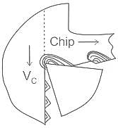
There are two basic mechanisms that accomplish chip formation are:
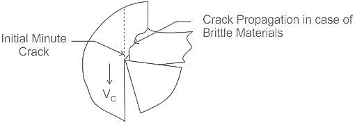
1. Yielding: generally for ductile materials.
2. Brittle fracturing: for brittle material.
The nature and amount of deformation of the chips due to the primary and the secondary shear deformations of the chips ahead and along the tool face depend upon

  • Work material.
  • Tool: material and geometry.
  • Cutting velocity (Vc ) and feed.
  • Cutting fluid application.

Continuous chips -
Continuous chips are formed in machining ductile material
such as mild steel, wrought iron, copper and aluminium. Basically, this operation is one of shearing the work material to form the chip and sliding the chip along the face of the cutting tool.
The formation of the chip takes place in a zone extending from the tool cutting edge to the junction between the surfaces of the chip and workpiece. This zone is known as the primary deformation zone. To deform the material in this manner the forces must be transmitted to the chip across the interface between the chip and tool are sufficient to deform the lower layers of the chip as it slides along the tool face (secondary deformation zone).

Discontinuous chips -

  • During the formation of a chip, the material undergoes severe strain and fracture will occur in primary deformation zone when the chip is only partly formed. Under these conditions the chip is segmented and the condition is referred to as discontinuous chip formation. Discontinuous chips are produced when machining such materials as cast iron or cast brass but may also be produced when machining ductile material at very low speeds and high feeds.

Built up edge formation -

  • In machining ductile metals such as steels with wide chip-tool contact length, a lot of stress and temperature develop in the secondary deformation zone at the chip–tool interface. Under such high stress and temperature in between two clean surfaces of metals, strong bonding may locally take place due to adhesion similar to welding.
  • Such bonding will be encouraged and accelerated if the chip and tool materials have mutual affinity or solubility. The weldment starts forming as an embryo at the most favourable location and then gradually grows, this mechanism in known as built up edge formation(BUE).

Formation of BUE causes several harmful effects, such as:
1) It unfavourably effects the rake angle at the tool tip causing an increase in cutting forces and power consumption.
2) Repeated formation and dislodgement of the BUE causes fluctuation in cutting forces and thus induces vibration which is harmful to the tool, job and machine tool.
3) Surface finish gets deteriorated.
4) It may reduce tool life by accelerating tool wear at its rake surface by successive adhesion, grain pullout and flaking.

ESE (ME) Paper II Mock Test - 1 - Question 12

Which one of the following sensors is a special type of force sensor composed of a matrix of force-sensing elements?

Detailed Solution for ESE (ME) Paper II Mock Test - 1 - Question 12

Tactile Array Sensor:

  • A tactile array sensor is a special type of force sensor composed of a matrix of force-sensing elements.
  • The force data provided by this type of device may be combined with pattern recognition techniques to describe a number of characteristics of the impression contacting the array sensor surface.
  • Some of the characteristics are as follows:
    1. Presence of an object
    2. Object’s contact area, shape, location, and orientation
    3. Pressure and its distribution
    4. Force magnitude and location
  • Tactile array sensors can be mounted in the fingers of the robot gripper or attached to a work table as a flat touch surface.

Touch Sensor:

  • A touch sensor is a sensor that is capable of capturing and recording the physical touch made by the operator. It is also referred to as a touch detector.
  • The application of touch sensors are as follows:
    • Commonly used in robotics enabling basic movement and the ability to detect a touch in its surroundings.
    • Smartphones, automotive, industrial applications.

Range Sensor:

  • A range sensor is a sensor that measures the distance between the object and the robot's hand, within its range of operation.
  • Range sensors find use in robot navigation and avoidance of obstacles in the path.

Proximity Sensor:

  • A proximity sensor is a non-contact sensor that detects the presence of a target when the target enters the sensor’s field.
  • Depending on the type of proximity sensor sound, light, infrared radiation (IR), or electromagnetic fields may be utilized by the sensor to detect a target.
  • Proximity sensors are used in phones, recycling plants, self-driving cars, anti-aircraft systems, and assembly lines.
ESE (ME) Paper II Mock Test - 1 - Question 13

A fluid of viscosity 0.7 Ns/m2 and specific gravity 1.3 is flowing through a circular pipe of diameter 100 mm. The maximum shear stress at the pipe wall is given as 196.2 N/m2. What is the pressure gradient of the flow?

Detailed Solution for ESE (ME) Paper II Mock Test - 1 - Question 13

Concept:
Maximum Shear Stress in Circular Pipe Flow is given by


where T = Maximum Shear Stress, R = Radius of Pipe, dp/dx = Pressure Gradient
Calculation:
Given:
T = 196.2 N/m2, R = 100/2 = 50 mm

dp/dx = - 7848 N/m2 per m
The Pressure Gradient is - 7848 N/m2 per m.

ESE (ME) Paper II Mock Test - 1 - Question 14

Lumped system analysis assumes a uniform temperature distribution throughout the body, which will be the case only when the thermal resistance of the body to heat conduction is

Detailed Solution for ESE (ME) Paper II Mock Test - 1 - Question 14

In general, the temperature of a body varies with time as well as position.

Lumped system analysis -

Interior temperatures of some bodies remain essentially uniform at all times during a heat transfer process. The temperature of such bodies are only a function of time, T = T(t). The heat transfer analysis based on this idealization is called lumped system analysis. Which will happen only when the body possesses an infinite value of thermal conductivity or the body have zero thermal resistance to heat conduction.

The Biot number is the ratio of the internal resistance (conduction) to the external resistance to heat convection. Lumped system analysis assumes a uniform temperature distribution throughout the body, which implies that the conduction heat resistance is zero.

Thus, the lumped system analysis is exact when Bi = 0.

It is generally accepted that the lumped system analysis is applicable if Bi <= 0.1.

Therefore, small bodies with high thermal conductivity are good candidates for lumped system analysis.

ESE (ME) Paper II Mock Test - 1 - Question 15

Which one of the following is used in aircraft refrigeration?

Detailed Solution for ESE (ME) Paper II Mock Test - 1 - Question 15

Gas refrigeration cycle:

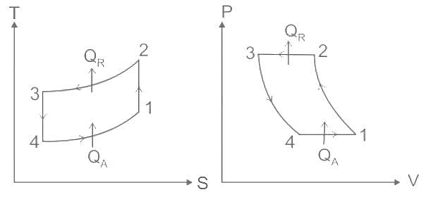
  • A gas refrigeration cycle works on the reverse Brayton cycle this cycle is also called Joule or Bell-Coleman cycle.
  • A gas cycle consists of two reversible isobaric and two reversible adiabatic processes.


Process 1 - 2: Reversible adiabatic compression
Process 2 - 3: Constant pressure heat rejection
Process 3 - 4: reversible adiabatic expansion (Throttling)
Process 4 - 1: Constant pressure heat addition

  • A Gas refrigeration cycle is used in the aircraft refrigeration system and the cycle is also called air refrigeration cycle.
  • Aircraft have high cooling loads because of large occupancy, electronic equipment and high velocity and high heat generation due to skin friction.
  • The power ton of refrigeration is higher than the VCRS system.
  • The weight per ton of refrigeration is low due density of air and space and the volume required is less.
  • The small amount of leakage is tolerable with air as the refrigerant.
  • Availability of refrigerant in mid-air.
  • Cabin pressurization and air conditioning can be combined into one operation..
  • In aircraft, weight is the primary concern. So, for aircraft a refrigeration system which can provide more cooling with low weight, is required. That's why in aircraft, gas refrigeration system are employed.

Additional Information
Vapour compression Refrigeration system:

Process 1 - 2: Reversible adiabatic compression
Process 2 - 3: Constant pressure heat rejection
Process 3 - 4: Irreversible expansion (Throttling)
Process 4 - 1: Constant pressure heat addition
Simple vapour Absorption System:

  • A simple vapour absorption system consists of an absorber, a pump, a generator and a pressure-reducing valve to replace the compressor of the vapour compression system.
  • The other components of the system are the condenser, expansion valve and evaporator as in the vapour compression system.
  • Ammonia is used as a refrigerant while water is used as an absorbent.
  • Liquid ammonia (normally a mixture of liquid and vapour) from the expansion valve enters the evaporator, either it absorbs heat from the evaporator space or it cools the secondary refrigerant in a heat exchanger.
  • Normally these units have a large cooling capacity of the order of 80 TR and above.
  • In such units, liquid ammonia absorbs heat from the secondary refrigerant which would be used as a medium to cool the space or products in the refrigerated space.

Steam ejector cycle refrigeration:

  • An ejector refrigeration system can be considered a modification of a conventional vapour compression refrigeration System (VCRS).
  • An ejector takes the place of a compressor to pressurize the refrigerant vapour flowing from an evaporator and discharge it to a condenser.
  • Working fluid is heated at high pressure and temperature in the generator.
  • The high-pressure refrigerant vapour enters the nozzle.
  • Working fluid is then accelerated to a high velocity and entrains motive steam from the evaporator, resulting in a cooling effect.
  • After that, mixed vapour steams are discharged from the nozzle to the condenser where they are cooled down and condensed to liquid fluids.
  • A part of the liquid refrigerant returns to the evaporator through an expansion valve whereas the other part is pumped to the generator.
ESE (ME) Paper II Mock Test - 1 - Question 16

The water in a jet-propelled boat is drawn amid-ship and discharged at the back with an absolute velocity of 15 m/s. The boat speed is 30 km/hr. The cross-sectional area of the jet at the back is 0.03 m2. What is the efficiency of the jet propulsion?

Detailed Solution for ESE (ME) Paper II Mock Test - 1 - Question 16

Concept:-
Jet propulsion, similar to all means of propulsion, is based on Newton’s Second and Third laws of motion.

Propulsive efficiency is defined as the ratio of thrust power (TP) and propulsive power (PP) and is the measure of the effectiveness with which the kinetic energy imparted to the fluid is transformed or converted into useful work. Thus, propulsive efficiency ηp is given by,

Where,

VB = Speed of the boat in m/s

V = Absolute velocity of the water in m/s

Calculation:-

Given:-

V = 15 m/s

VB = 30 km/hr = 8.333 m/s

Cross-sectional area of jet = 0.03 m2

On putting all values in the formula,

⇒ ηp ≈ 71.43 %

ESE (ME) Paper II Mock Test - 1 - Question 17

Which one of the following statements is correct?

Detailed Solution for ESE (ME) Paper II Mock Test - 1 - Question 17

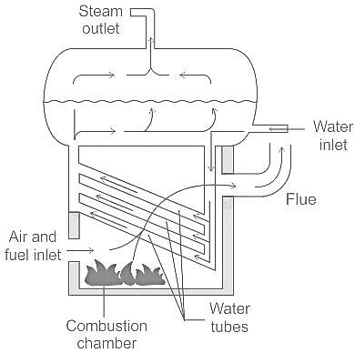
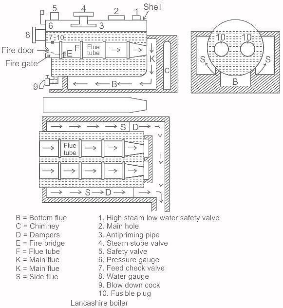
Water Tube Boiler:

  • A water Tube Boiler is a type of boiler in which the water is flowing inside the tube and hot gases which are produced by the combustion chamber have surrounded the tube and the further boiler is used for the generation of electricity.
  • The working principle of a water tube boiler is thermal siphoning (circulation of natural water).
  • Basically, this type of boiler includes two drums namely steam, lower or mud drum.

The following water tube boiler is:

  • Benson Boiler
  • Babcock and Wilcox Boiler
  • Lamont Boiler
  • Loeffler boiler and
  • Yarrow boiler.

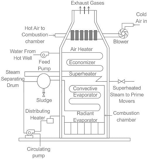
High-pressure boiler:

  • A high-pressure boiler is a type of boiler that operates at a pressure above 80 bars.
  • They are widely used in thermal power plants for the generation of power.
  • The circulation of water through a boiler may be natural or Forced type.
  • In all modern high-pressure boiler plants, water circulation is with the help of a Pump i.e. by means of Forced Circulation.
  • To avoid large resistance to the flow of water, these boilers have a parallel set of an arrangement of tubes.
  • High-pressure boilers are characterized by the use of a very small steam-separating drum or by a complete absence of any drum.
  • Above the critical pressure, the Saving of heat takes place by the evaporation of water.

There are two types of High-pressure boilers and are as follows:

  • Benson Boiler
  • Lamont Boiler

Lancashire Boiler:

  • This is an internally fired boiler because the furnace uses to present inside the boiler.
  • This boiler generates low-pressure steam and it is a natural circulation boiler.
  • It has high thermal efficiency of about 80 to 90 percent.
  • The size is approximately 7-9 meters in length and 2-3 meters in diameter.
  • It is mostly used in locomotive engines and marines etc.

Stirling Boiler:

  • The Stirling boiler is one type of water tube boiler, used for generating steam (50,000 kg steam/hour and 60 kgf /cm2 pressure) in the large area of the stationary plant.
  • Stirling boilers are externally fired boiler.
  • This type of boiler consists of 3 steam drums as well as 2 mud drums.
  • The steam drums are located on the top section of the boiler whereas mud drums are located on the base of the arrangement.
  • The steam drums and mud drums are connected through bent tube banks.
  • When the tubes are turned then the mechanical pressures due to pipes extension throughout heating cannot influence the system.
  • The two drums as well as tubes are designed of steel which will support the total system.
  • The arrangement of the Stirling boiler is enclosed with brickwork. Here, the arrangement of bricks will avoid the heat dissipation in the surroundings

ESE (ME) Paper II Mock Test - 1 - Question 18

Alternative paths provided by vertical paths from the main rung of a ladder diagram, that is, paths in parallel, represent

Detailed Solution for ESE (ME) Paper II Mock Test - 1 - Question 18

Concept:

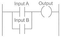
Alternative paths provided by vertical paths from the main rung of a ladder diagram, that is, paths in parallel, represent logical OR operations.

Below figure shows an OR logic gate system on a ladder diagram

The ladder diagram starts with ||, normally open contacts labeled input A, to represent switch A, and in parallel with it ||, normally open contacts labeled input B, to represent switch B.

Either input A or input B must be closed for the output to be energized. The line then terminates with ( ) to represent the output.

Additional information:

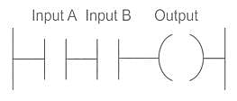
On a ladder diagram, contacts in a horizontal rung, that is, contacts in series, represent the logical AND operations.

ESE (ME) Paper II Mock Test - 1 - Question 19

To maintain 0.08 m3/s flow of petrol with a specific gravity of 0.7, through a steel pipe of 0.3 m diameter and 800 m length, with coefficient of friction of 0.0025 in the Darcy relation, the power required will be nearly

Detailed Solution for ESE (ME) Paper II Mock Test - 1 - Question 19

Concept:

Power required to maintain the head is given by

P = ρ g Q hf

The loss in a pipe is given by

Substituting V = 4Q/πd2

Here f – friction factor which is equal to 4 times of coefficient of friction.

Calculation:

Given Q = 0.08 m3/s, ρ = 0.7 × 1000 = 700 kg/m3, d = 0.3 m, L = 800 m, f = 4 × 0.0025 = 0.01;

Head loss will be

Power required will be

P = 700 × 9.81 × 0.08 × 1.741 = 0.956 kW ≈ 1 kW

ESE (ME) Paper II Mock Test - 1 - Question 20

A 4-cylinder, 4-stroke single-acting petrol engine consumes 6 kg of fuel per hour at 800 rpm when the air-fuel ratio of the mixture supplied is 9:1. The temperature is 650 K and the pressure is 12.5 bar at the end of the compression stroke. Take R = 300 Nm/kg-K, diameter of cylinder as 8 cm, stroke of cylinder as 10 cm. The compression ratio will be nearly

Detailed Solution for ESE (ME) Paper II Mock Test - 1 - Question 20

Mass flow rate of fuel = 6 kg/hr

Air Fuel Ratio = 9 : 1

T2 = 650 K

P2 = 12.5 bar = 1250 kPa

R = 300 Nm/kg.K , N = 800 rpm

K (No. of cylinders) = 4

Solution:

Mass flow rate of air (ma) = 9 6 = 54 kg/hr

Total rate of injection of air and fuel (m) = ma + mf = 60 kg/hr

Using equation:
P2V2 = mRT2
V2 = mRT2/P2

V2 = 2.6 ×10⁻³m3/sec

Swept Volume (Vs) = ALNK/60

Vs =

Vs = 0.0134 m3/sec

Also, Vs = V1 - V2

V1 = V2 + Vs = (2.6 x 10⁻³) + 0.0134

V1 = 0.016 m3

∴ Compression ratio = = 6.153 6.2

ESE (ME) Paper II Mock Test - 1 - Question 21

A 13 mm diameter tensile specimen has 50 mm gauge length. If the load corresponding to the 0.2% offset is 6800 kg, the yield stress will be nearly

Detailed Solution for ESE (ME) Paper II Mock Test - 1 - Question 21

Concept:
σyield = P/A
where σyield = Yield Stress, P = Load Applied, A = Area of Specimen.
Calculation:
Given:
At 0.2 offset, corresponding load (P) = 6800 kg
Gauge diameter, d = 13 mm

Area (A) = π/4 × d2 = π/4 × 132

Yield stress, σyield =

∴ σyield = 51.23 kg/mm2 ≃ 51.23 kg/mm2

ESE (ME) Paper II Mock Test - 1 - Question 22

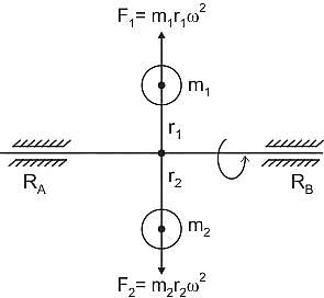
A mass m1 attached to a shaft at radius r1, rotating with angular velocity ω rad/s, can be balanced by another single mass m2 which is attached to the opposite side of the shaft at radius r2, in the same plane, if

Detailed Solution for ESE (ME) Paper II Mock Test - 1 - Question 22

Concept:
The shaft is rotating in a plane with angular velocity ω rad/sec.
The mass m1 is attached at a distance of r1 and mass m2 is attached at a distance of r2

Now in the same plane according to internal balancing we know that,
m1r1ω2 = m2r2ω2
m1r1 = m2r2 (∵ Angular velocity ω is same for both the masses as both of them are attached to the
same shaft or ω1 = ω2 = ω)
Here, the center of gravity lies on the same axis.
RA = RB =0 means no dynamic reactions at the supports. Therefore, the shaft is free from any dynamic bending stresses.

Important Point

  • There are two types of balancing i.e. External balancing and Internal balancing.
  • Balancing is generally referred as external balancing.
ESE (ME) Paper II Mock Test - 1 - Question 23
Which one of the following may be considered as a single cylinder two-stroke reciprocating engine running at 2400 rpm to 2700 rpm for rapid chain of impulses?
Detailed Solution for ESE (ME) Paper II Mock Test - 1 - Question 23

Concept:

A pulsejet engine (or pulse jet) is a type of jet engine in which combustion occurs in pulses.

Pulsejet engines are a lightweight form of jet propulsion, but usually have a poor compression ratio, and hence give a low specific impulse.

Pulsejet engines are characterized by simplicity, low cost of construction, and high noise levels. While the thrust-to-weight ratio is excellent, thrust specific fuel consumption is very poor.

The pulsejet uses the Lenoir cycle.

Pulse jet engines have stable operation in range of 45 cycles per second.

This can be correlated to a 2-stroke engine running at 2400 - 2700 rpm (40 - 45 cycles/sec).
ESE (ME) Paper II Mock Test - 1 - Question 24

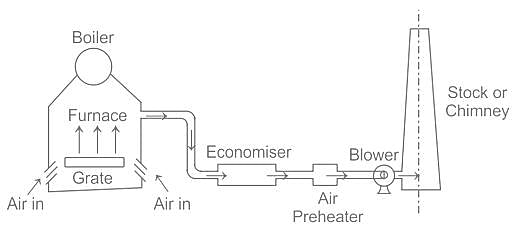
The partial vacuum created by the fan in the furnace and flues, draws the products of the combustion from the main flue and allows them to pass up to the chimney. Such a draught is called

Detailed Solution for ESE (ME) Paper II Mock Test - 1 - Question 24

Concept:
In induced draught system a fan (or) blower is located at (or) near the base of the chimney.
The pressure over the fuel bed is reduced below that of the atmosphere.
By creating a partial vacuum in the furnace and flues, the products of combustion are drawn from the main flow and they pass up the chimney

ESE (ME) Paper II Mock Test - 1 - Question 25

Which of the following are related to the Proton Exchange Membrane Fuel Cell (PEMFC)?
1. Polymer electrolyte
2. Hydrogen fuel and oxygen
3. Pure water and small amount of electricity
4. Nitrogen gas

Detailed Solution for ESE (ME) Paper II Mock Test - 1 - Question 25

Concept:

A fuel cell is a device that converts chemical potential energy (energy stored in molecular bonds) into electrical energy.

A PEMFC (Proton Exchange Membrane Fuel cell) uses hydrogen gas (H2) and oxygen gas (O2) as fuel.

The products of the reaction in the cell are pure water, high electricity, and less heat.

They are also known as polymer electrolyte membrane (PEM) fuel cells.

PEMFCs have attracted great attention due to their numerous advantages, such as high power density, high energy conversion efficiency, fast startup, low sensitivity to orientation, and environmental friendliness.

Working:

In PEMFCs, the fuel (hydrogen, H2) enters at the anode. There, a chemical reaction causes the hydrogen molecules to separate into positive hydrogen ions (H+ or protons) and electrons (e−). This reaction releases heat.

The positive hydrogen ions pass through the electrolyte made of a polymer membrane and travel to the cathode.

The electrons remain behind and thereby give the anode a negative charge, creating a voltage difference between the anode and the cathode. Because electrons travel from negative to positive, the electrons follow an external circuit from the anode to the cathode.

At the same time, oxygen (O2) enters the fuel cell at the cathode and combines there with the electrons, which have traveled through the external circuit, and the positive hydrogen ions, which have traveled through the electrolyte, to produce water (H2O) at the cathode.

ESE (ME) Paper II Mock Test - 1 - Question 26

A punch is used for making holes in steel plates with thickness 8 mm. If the punch diameter is 20 mm and force required for creating a hole is 110 kN, the average shear stress in the plate will be nearly

Detailed Solution for ESE (ME) Paper II Mock Test - 1 - Question 26

Concept:

In punching and blanking, the shearing action on the sheet takes place which will depend on the shear strength of the metal.

Punching force F = Lt τ

Where L is Length of the periphery, t = thickness, τ = Ultimate shear strength

For circular section L = πd

∴ F = πDtτ

τ = F/πDt

Calculation:

Given t = 8 mm, D = 20 mm, F = 110 kN;

Nearest option is 219 MPa

ESE (ME) Paper II Mock Test - 1 - Question 27

The percentage of hydrogen in producer gas is

Detailed Solution for ESE (ME) Paper II Mock Test - 1 - Question 27

Composition of producer gas:

A combustible mixture of nitrogen, carbon monoxide, and hydrogen, generated by passing air with steam over burning coke or coal in a furnace and used as fuel also called air gas.

Typical components of producer gas:

Producer gas is usually a mixture of mainly carbon monoxide (CO), hydrogen (H2), methane, small amounts of Argon (Ar).

Apart from the main species, the gas contains various minor species, tars, and particulates depending on the feedstock and the production method.

Generally;

19% CO, 18% H2, 1% CH4, 11% CO2 and the rest N2.

ESE (ME) Paper II Mock Test - 1 - Question 28

A diesel engine has a compression ratio of 20 and cut-off takes place at 5% of the stroke. What is the cut-off ratio?

Detailed Solution for ESE (ME) Paper II Mock Test - 1 - Question 28

Concept:
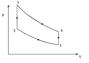
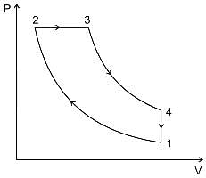
Diesel cycle:


Comression ratio (r) = v1/v2
Cutt − off ratio (ρ) = v3/v2
If cut-off happens at k% of the stroke, then
Cut-off ratio (ρ) = 1 + k(r - 1)
Calculation:
Given:
r = 20, k = 5%, ρ = ?
(ρ) = 1 + k(r - 1)
∴ 1 + 0.05(20 - 1) = 1.95

ESE (ME) Paper II Mock Test - 1 - Question 29

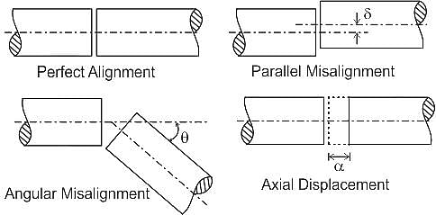
Parallel misalignment is present when

Detailed Solution for ESE (ME) Paper II Mock Test - 1 - Question 29

Parallel misalignment is present when the centre lines of both shafts are parallel but they are offset in same plane.

ESE (ME) Paper II Mock Test - 1 - Question 30

The ideal hydraulic rotary actuator provides shaft torque, T, which is

Detailed Solution for ESE (ME) Paper II Mock Test - 1 - Question 30

Rotary actuator:

  • A rotary actuator is based on the principle of a gear motor. Fluid enters at the top with high pressure, applying force on the gear faces resulting in rotation.
  • The design and construction of a vane motor are similar to a vane pump.
  • At the entry, a vane has high pressure on one side, whereas on the other side the pressure will be very low due to the high pressure of the fluid.
  • This difference in the pressure exerted on the vane will produce a torque that would result in the rotation of the vanes.
  • Therefore, rotary actuators are the hydraulic or pneumatic equivalent of electric motors which are used when twisting or turning motion is required and is proportional to the differential pressure.
View more questions
Information about ESE (ME) Paper II Mock Test - 1 Page
In this test you can find the Exam questions for ESE (ME) Paper II Mock Test - 1 solved & explained in the simplest way possible. Besides giving Questions and answers for ESE (ME) Paper II Mock Test - 1, EduRev gives you an ample number of Online tests for practice

Top Courses for Mechanical Engineering

Download as PDF

Top Courses for Mechanical Engineering