Mechanical Engineering Exam  >  Mechanical Engineering Tests  >  ESE (ME) Paper II Mock Test - 3 - Mechanical Engineering MCQ

ESE (ME) Paper II Mock Test - 3 - Mechanical Engineering MCQ


Test Description

30 Questions MCQ Test - ESE (ME) Paper II Mock Test - 3

ESE (ME) Paper II Mock Test - 3 for Mechanical Engineering 2024 is part of Mechanical Engineering preparation. The ESE (ME) Paper II Mock Test - 3 questions and answers have been prepared according to the Mechanical Engineering exam syllabus.The ESE (ME) Paper II Mock Test - 3 MCQs are made for Mechanical Engineering 2024 Exam. Find important definitions, questions, notes, meanings, examples, exercises, MCQs and online tests for ESE (ME) Paper II Mock Test - 3 below.
Solutions of ESE (ME) Paper II Mock Test - 3 questions in English are available as part of our course for Mechanical Engineering & ESE (ME) Paper II Mock Test - 3 solutions in Hindi for Mechanical Engineering course. Download more important topics, notes, lectures and mock test series for Mechanical Engineering Exam by signing up for free. Attempt ESE (ME) Paper II Mock Test - 3 | 150 questions in 180 minutes | Mock test for Mechanical Engineering preparation | Free important questions MCQ to study for Mechanical Engineering Exam | Download free PDF with solutions
ESE (ME) Paper II Mock Test - 3 - Question 1

The heat-treatment process used to soften hard alloy and tool steels so that they can be more easily machined is called

Detailed Solution for ESE (ME) Paper II Mock Test - 3 - Question 1

Annealing
Annealing involves heating the steel to a suitable temperature, holding it at that temperature for some time and then cooling it slowly. There are different methods of cooling. The main purpose of Annealing is to reduce the hardness of a material. Besides this, it is also used -

  • To relieve the internal stress of a material
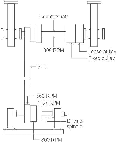
  • To restore ductility to perform the further operation on the material
  • To increase the machinability of the material
  • To induce softness

Additional Information
Carburizing

  • It is a process used to case-harden steel with a carbon content between 0.1 and 0.3 wt% C.
  • In this process, steel is introduced to a carbon-rich environment and elevated temperatures for a certain amount of time, and then quenched so that the carbon is locked in the structure.

Normalizing:

  • Heat the steel from 30°C to 50°C above its upper critical temp, held about fifteen minutes and then allowed to cool down in still air. The homogeneous structure provides a higher yield point, ultimate tensile strength and impact strength with lower ductility to steels.
  • The main purpose of normalizing is to refine grain size.
  • Main objective:
    • Refine grain size in metal, improve strength and hardness, reduce ductility
    • Remove cold worked stress.
    • Remove dislocations due to hot working.

Tempering ​

  • Tempering is a heat treatment process in which the hardness of a hardened alloy is reduced by the appropriate heat treatment process; for example, steel hardened by the formation of martensite formation can be tempered.
  • Tempering is a heat-treatment process consisting of reheating the hardened steel to a temperature below 400°C, followed by cooling.
  • Purpose of tempering the steel
  • Steel in its hardened condition is generally too brittle to be used for certain functions. Therefore, it is tempered. The aims of tempering are:
    • to relieve the internal stresses
    • to regulate the hardness and toughness
    • to decrease the brittleness
    • to restore some ductility
    • to induce shock resistance
    • to Improving the toughness (strength)
ESE (ME) Paper II Mock Test - 3 - Question 2

Morse test was conducted for a 2-stroke spark ignition engine having 2 – cylinders and the following data is obtained.
Brake power = 14 kW, Brake Power of individual cylinder = 5.4 kW, 4.80 kW.
What is the mechanical efficiency of this engine?

Detailed Solution for ESE (ME) Paper II Mock Test - 3 - Question 2

Concept:
Let the cylinders be 1 and 2
Net brake power bp1,2
Indicated power = Brake power + Frictional power
Ip = bp + fp

ip1,2 = net indicated power = ip1 + ip2
Calculation:
Given:

bp1,2 = 14 kW, bp1 = 5.4 kW, bp2 = 4.80 kW
ip1-2 = bp1-2 + fp
ip1 = bp1 + fp
ip2 = ip1-2 – ip1
∴ ip2 = bp1-2 + fp – bp1 – fp
ip2 = bp1-2 – bp1
ip2 = 14 – 5.4
∴ ip2 = 8.6 kW
Now,

ip1 = bp1-2 – bp2
∴ ip1 = 14 – 4.8
∴ ip1 = 9.2 kW
Now,

ip1-2 = 9.2 + 8.6
∴ ip1-2 = 17.8 kW
Now

ηm = bp1-2/ip1-2 = 14/17.8
∴ ηm = 78.65 %

1 Crore+ students have signed up on EduRev. Have you? Download the App
ESE (ME) Paper II Mock Test - 3 - Question 3

Refrigerant R–717 is

Detailed Solution for ESE (ME) Paper II Mock Test - 3 - Question 3


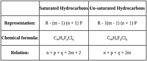
where m = No. of Carbon atoms, n = No. of Hydrogen atoms, p = No. of Florine atoms, q = No. of Chlorine atoms.
If the refrigerant is Inorganic Compound
R – (Molecular Weight + 700)

Ammonia NH3 whose molecular weight is 17 and the chemical formula is R – 717.
Water H20 whose molecular weight is 18 and the chemical formula is R – 718.
Carbon dioxide CO2 whose molecular weight is 44 and the chemical formula is R – 744.

ESE (ME) Paper II Mock Test - 3 - Question 4
The hoop stress induced in a thick cylinder due to radial pressure will be
Detailed Solution for ESE (ME) Paper II Mock Test - 3 - Question 4

Concept-

For thick cylinders such as guns, pipes to hydraulic presses, high pressure hydraulic pipes the wall thickness is relatively large and the stress variation across the thickness is also significant.

Hoop or Circumferential Stress– This is directed along the tangent to the circumference and tensile in nature.

The hoop stress induced in a thick cylinder due to radial pressure will be tensile in nature.

Longitudinal Stress– This stress is directed along the length of the cylinder. This is also tensile in nature and tends to increase the length.

Radial pressure– It is compressive in nature. Its magnitude is equal to fluid pressure on the inside wall and zero on the outer wall if it is open to atmosphere.

ESE (ME) Paper II Mock Test - 3 - Question 5
In condition based monitoring, the techniques like lubricating oil analysis, spectrographic analysis, ferrography and wear particle analysis comes under
Detailed Solution for ESE (ME) Paper II Mock Test - 3 - Question 5

Concept:

Conditions monitoring is one of the maintenance methods which are used to assess the health and condition of equipment’s machines, systems or process by absorbing checking, measuring and monitoring several parameters. This technique is also called as equipment health monitoring.

The various techniques involved in condition monitoring are

Vibration Monitoring – determines the actual condition of equipment / machines by studying the noise or vibration produced during functioning.

Thermography – determines the condition of plant machinery systems etc by studying the emission of infra-red energy i.e. temperature.

Tribology – determines the dynamic condition of bearing lubrication, rotor support structure of machinery etc by adopting any one of the techniques like lubricating oil analysis, spectrographic analysis, ferrography and wear particle analysis.

Electrical Motor Analysis – determines the problem within motors and other electrical equipment.

Visual inspection - determines the conditions of working elements visually based on the experience.

ESE (ME) Paper II Mock Test - 3 - Question 6
In which gasifier, primary gasification air is introduced at or above the oxidation zone in the gasifier and the producer gas is removed at the bottom of the apparatus?
Detailed Solution for ESE (ME) Paper II Mock Test - 3 - Question 6

Concept:

Gasification is the process of converting organic materials (anything containing carbon) into a gas form known as Syngas or Producer Gas.

Based on the direction of fuel and gas, gasifiers are classified into two types namely

1) Updraft gasifier (or) Counter current gasifier:

The oldest and simplest type of gasifier is the counter current or updraft gasifier.

With updraft gasification, the fuel is supplied at the top and the air at the bottom so that fuel moves against the air flow.

2) Downdraft gasifier (or) Co current gasifier:

The downdraft design is essentially the same as the updraft design except that feed and air move concurrently from top to bottom of the gasifier.

Advantage of the downdraft fixed-bed gasifier is that the tars are cracked down in the oxidation zone, thus the producer gas has lower tar content compared to other types of gasifiers.

3) Cross draft gasifier:

In this design, the biomass feed is introduced from the top and the air is from the side of the gasifier. The biomass moves down as it gets dried and finally, gasified while the air exits from the opposite side of the unit. The exit for the gas is more-or-less at the same level as that of entrance.

ESE (ME) Paper II Mock Test - 3 - Question 7

What is shear of rivet?

Detailed Solution for ESE (ME) Paper II Mock Test - 3 - Question 7

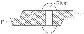
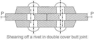
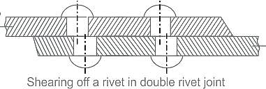
Shearing of the rivets:

  • The plates which are connected by the rivets exert tensile stress on the rivets, and if the rivets are unable to resist the stress, they are sheared off.
  • The resistance offered by a rivet to be sheared off is known as shearing resistance or shearing strength or shearing value of the rivet.

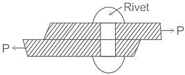
Single shear is given in the diagram below.

Additional Information

ESE (ME) Paper II Mock Test - 3 - Question 8

Which of the following represent the Darcy’s friction factor in terms of Reynolds number (Re) for the laminar flow in circular pipes?

Detailed Solution for ESE (ME) Paper II Mock Test - 3 - Question 8

Darcy Weisbach Equation for friction losses in circular pipe:
hf = f x l x v2/2 x g x D 
where,
L = length of the pipe, D = diameter of the circular pipe, V = mean velocity of the flow, f = Darcy’s friction
factor = 4 × F’, F’ = coefficient of friction, hf = head loss due to frictionFor Laminar Flow
Friction Factor f = 64/Re and F' = 1/4 X 64/Re = 16/Re
For Turbulent flow

ESE (ME) Paper II Mock Test - 3 - Question 9

Statement (I): The thermal efficiency of a regenerative Rankine cycle is always higher than that of a cycle without regeneration.
Statement (II): In the regeneration cycle, the work output is more.

Detailed Solution for ESE (ME) Paper II Mock Test - 3 - Question 9

Concept:
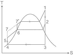
Regeneration in the Rankine cycle
:

  • Regeneration means taking some part of the heat from the expanding steam in the turbine to decrease the overall heat supplied in the process.
  • The thermal efficiency of the Rankine cycle can be increased by the use of a regenerative heat exchanger.
  • In the regenerative cycle, a portion of the partially expanded steam is drawn off between the high and low-pressure turbines.
  • The steam is used to preheat the condensed liquid before it returned to the boiler.
  • In this way, the amount of heat added at the low temperatures is reduced and the mean effective temperature of heat addition is increased, thus cycle efficiency is increased.
  • At point 2 some amount of steam is taken out for the heating purpose of water.

Effect of Regeneration:

  • Decrease in turbine work due to a decrease in the mass flow rate of steam.
  • The decrease in heat rejection in the condenser due to a reduction in mass flow rate.
  • Increased efficiency and mean temperature of heat addition (Tm).

Both the statements are true but statement 2 is not explaining statement 1.

ESE (ME) Paper II Mock Test - 3 - Question 10

Select the correct statement about crystal defects.

1) Due to Frankel defect density of ionic solid decreases.

2) Ionic solid, with Schottky defect, contains equal number of cation and anion vacancies in their structure.

3) As the grain size of metal increases its strength decreases

Detailed Solution for ESE (ME) Paper II Mock Test - 3 - Question 10

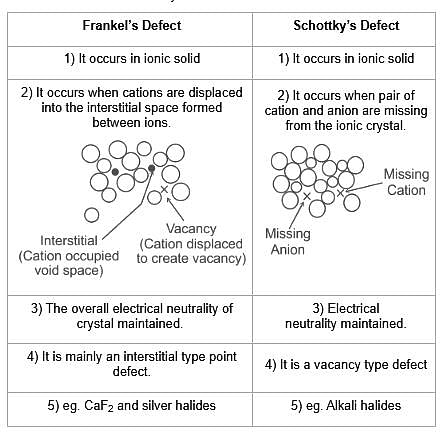
Frankel’s Defect and Schottky’s Defect:

→ Since electrical neutrality maintained so due to defects, the density of the solid is not affected.
[Statement 1 wrong]
→ Ionic solid contain equal no. of cation and anion vacancy hence,
[Statement 2 correct]
→ Smaller grains have a greater ratio of surface area to the volume which means a greater ratio of grain boundary to dislocation so more grain size decreased strength.
Statement (3) correct.
The correct option is 2.

ESE (ME) Paper II Mock Test - 3 - Question 11

Which of the following is not the correct procedure to increase the fatigue limit

Detailed Solution for ESE (ME) Paper II Mock Test - 3 - Question 11
  • Decarburization is the process in which the content of carbon is depleted from the steel or other alloy surfaces.
  • It is the opposite of the carburization process.
  • Surface decarburization is not the correct procedure to increase the fatigue limit since it will have adverse effects like reduced ductility and increased susceptibility of crack initiation.

Cold working or Cold Forming:

  • Cold working is the plastic deformation process where metal is processed below the re-crystallization temperature.
  • Most of the time cold forming is done at room temperature.
  • The major cold-working operations can be classified basically as rolling, squeezing, bending, shearing, and drawing.

Shot peening

  • It is a cold work process used to finish metal parts to prevent fatigue and stress corrosion failures and prolong product life for the part.
  • In shot peening, a small spherical shot bombards the surface of the part to be finished.
  • The shot acts like a peen hammer, dimpling the surface and causing compression stresses under the dimple.
  • The surface compression stress strengthens the metal, ensuring that the finished part will resist fatigue failures, corrosion fatigue and cracking, and galling and erosion from cavitation.

Understressing: The initial applied stress level is lower than the fatigue limit for a period of time, then cyclic stressing above the fatigue limit. This under-stressing increases the fatigue limit (might be due to strain hardening on the surface).

ESE (ME) Paper II Mock Test - 3 - Question 12

Consider the following statements regarding transmission shafts:
1. Counter shaft is secondary shaft which is driven by the main shaft from which the power is supplied to a machine component.
2. Jack shaft is an intermediate shaft between two shafts that is used in transmission of power.
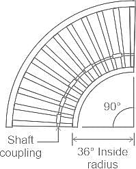
3. A line shaft consists of a number of shafts, which are connected in an axial direction by means of couplings.
Which of the above statements is/are correct?

Detailed Solution for ESE (ME) Paper II Mock Test - 3 - Question 12

Countershaft:

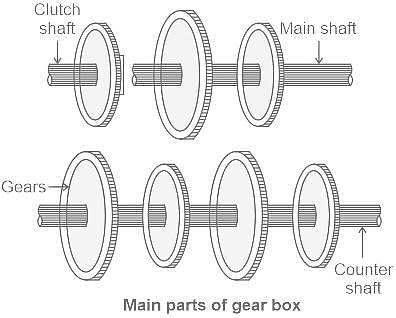
  • It is a secondary shaft, which is driven by the main shaft and from which the power is supplied to a machine component often, the countershaft is driven from the main shaft by means of pair of spur or helical gears and thus rotates counter to the direction of the main shaft.
  • A countershaft is a shaft that runs parallel to the main shaft in a gearbox and carries the pinion wheels.
  • In a normal sliding gear transmission, there are two shafts, the main shaft and a countershaft. A countershaft is a manual transmission shaft driven by the clutch shaft and its input gear.

Jack shaft:

  • It is an auxiliary or intermediate shaft between two shafts that are used in the transmission of power.
  • It’s function is the same as a countershaft.
  • A jackshaft is often just a short stub with supporting bearings on the ends and two pulleys, gears, or cranks attached to it.
  • In general, a jackshaft is any shaft that is used as an intermediary transmitting power from a driving shaft to a driven shaft.

Line shaft:

  • It consists of a number of shafts, which is connected in the axial direction by means of coupling.
  • It is popular in workshops using group drives.
  • In the simplest definition, a line shaft is the rotating shaft part of a system of mechanical couplings between the power source in a factory and the machines that do work.
  • These rotating shafts transmit mechanical energy throughout the factory and were usually interconnected to each other and to machines using various systems of pulleys, gears, and other mechanical methods.
  • These are also used as conveyors in industries.

  • A typical line shaft would be suspended from the ceiling of one area and would run the length of that area.
  • One pulley on the shaft would receive the power from a parent line shaft elsewhere in the building.
  • The other pulleys would supply power to pulleys on each individual machine or to subsequent line shafts.
  • In manufacturing where there were a large number of machines performing the same tasks, the design of the system was fairly regular and repeated.
  • In other applications such as machine and wood shops where there was a variety of machines with different orientations and power requirements, the system would appear erratic and inconsistent with many different shafting directions and pulley sizes.
ESE (ME) Paper II Mock Test - 3 - Question 13

Which one of the following instructions is conditional instruction which allow the user to change the order in which the processor scans the program?

Detailed Solution for ESE (ME) Paper II Mock Test - 3 - Question 13

Control Instruction:

  • Control instructions modify or change the flow of a program.
  • It is the instruction that alters the sequence of the program's execution, which means it changes the value of the program counter, due to which the execution of the program changes.
  • In other words, It is the instruction that allows the user to change the order in which the processor scans the program.
  • Features of Control Instruction:
    • These instructions cause a change in the sequence of the execution of the instruction.
    • This change can be through a condition or sometimes unconditional.
    • Flags represent the conditions.
    • Flag-Control Instructions.
    • Control Flow and the Jump Instructions include jumps, calls, returns, interrupts, and machine control instructions.
    • Subroutine and Subroutine-Handling Instructions.
    • Loop and Loop-Handling Instructions.

Sequence Instruction:

  • The order in which the instructions in a program are carried out is controlled by Sequence Instruction.
  • Normally the sequence proceeds in a linear fashion through the program, and the address of the instructions is obtained from the program counter in the control unit.

Communication Instruction:

  • Communication Instruction is used to establish communication between the processor and the computer program.

Arithmetic Instruction:

  • The arithmetic instructions define the set of operations performed by the processor's Arithmetic Logic Control Unit (ALU).
  • The arithmetic instructions are further classified into binary, decimal, logical, shift/rotate, and bit/byte manipulation instructions.
ESE (ME) Paper II Mock Test - 3 - Question 14

A capillary tube in a one-ton R22 air conditioner has a bore of 2⋅3 mm. Saturated liquid from the condenser enters at a temperature of 48°C and flows adiabatically through the tube until its temperature is 5°C. The friction factor is given as f = 0⋅32 / Re0⋅25. What is the length of the capillary tube? (Take intermediate sections at 40°C, 30°C, 20°C and 10°C and the mass flow rate of the refrigerant as 0.02417 kg/s)

Detailed Solution for ESE (ME) Paper II Mock Test - 3 - Question 14

Concept:
Analysis of flow through a Capillary tube:

  • The analysis of flow through a capillary tube was given by Hopkins and Cooper.
  • The flow through the capillary tube is actually compressible, three-dimensional and two-phase flow with heat transfer and thermodynamically metastable state at the inlet of the tube. However, to simplify the analysis, the flow is assumed to be steady, one-dimensional and in a single phase or a homogeneous mixture.
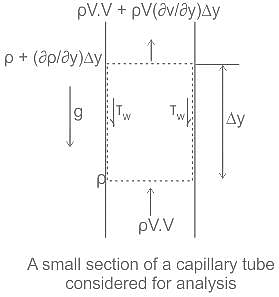
  • The below figure shows a small section of a vertical capillary tube with momentum and pressure at two ends of an elemental control volume.

Mass conservation:


The momentum theorem is applied to the control volume:
[Momentum]out - [Momentum]in = Total force on the control volume

  • At the face y + Δy, Taylor series expansion has been used for pressure and momentum and only the first-order terms have been retained.
  • The second-order terms with the second derivative and higher-order terms have been neglected. If the above equation is divided by πR2× Δy and limit Δy → 0 is taken, then all the higher-order terms will tend to zero if these were included since these will have Δy or its higher power of Δy multiplying them. Also ρavg will tend to ρ since the control volume will shrink to the bottom face of the control volume. Neglecting the gravity, we obtain:

The wall shear stress can be written in terms of friction factor. This will refer to as frictional pressure drop and a subscript 'f' will be used with it.

For fully developed flow the left-hand side of the equation (3) is zero, hence the frictional pressure drop Δpf may be obtained from the following equation:

The friction factor is defined as:

Substituting equation (5) in (4)

Substituting for τw in equation (3), we have:

Mass conservation equation (1) indicates that the product ρV is constant in the tube. It is called mass velocity and it is denoted by "G".

G = ρV
Mass flow rate, ṁ =

∴ ρV =  = G = constant .............................. (8)

So, eqn. (7) can be re-written as:

  • In this equation, the term on the left-hand side is the acceleration of the fluid. The first term on the right-hand side is the pressure drop required to accelerate the fluid and to overcome the frictional resistance. The second term on the right-hand side is the frictional force acting on the tube wall. The friction factor depends upon the flow Reynolds number and the wall roughness for the fully developed flow.
  • The velocity and reynolds number vary in a complex manner along the tube and these are coupled together. Hence an exact solution of equation (9) is not possible. To a good approximation the integral of the product 'fV', i.e. ∫ (fV)dy can be calculated by assuming an average value of the product 'fV' over a small length ΔL of the capillary tube.

Integrating equation (9) over a small length ΔL of the capillary tube, we obtain:


Δp is negative since pi > pi+1
Equation (11) can be expressed as
Δp = Δpaccln + Δpf
Calculation:
Given:
ṁ = 0.02417 kg / s, D = 2.3 mm

Area, A = =

From equation (8)

And mass flow rate, ṁ = ρ × A × V

From equation (5)

Using equation (12) in the above equation:


Let y = G/2D,
∴ (Δp)f = y × f × (ΔL) × V
Now, Reynolds number, Re =

Here, z = G × D = x D = 5.83 × 103 × 0.0023 = 13.409 Kg-s-1-m-1

ESE (ME) Paper II Mock Test - 3 - Question 15

Which one of the following fuel cells has lowest operating temperature?

Detailed Solution for ESE (ME) Paper II Mock Test - 3 - Question 15

Fuel cells: A fuel cell uses the chemical energy of hydrogen or other fuels to cleanly and efficiently produce electricity. Fuel cells are classified primarily by the kind of electrolyte they employ.

Types of fuel cells:

1. POLYMER ELECTROLYTE MEMBRANE FUEL CELLS (PEMFC):

  • Uses a solid polymer as an electrolyte and porous carbon electrodes containing a platinum or platinum alloy catalyst.
  • They need only hydrogen, oxygen from the air, and water to operate.
  • PEMFC operate at relatively low temperatures, around 80°C (176°F).
  • The low-temperature operation allows them to start quickly (less warm-up time) and results in less wear on system components, resulting in better durability

2. MOLTEN CARBONATE FUEL CELLS (MCFC):

  • MCFCs are high-temperature fuel cells that use an electrolyte composed of a molten carbonate salt mixture suspended in a porous, chemically inert ceramic lithium aluminum oxide matrix.
  • Improved efficiency is another reason MCFCs offer significant cost reductions over phosphoric acid fuel cells.

3. PHOSPHORIC ACID FUEL CELLS (PAFC):

  • The PAFC is considered the "first generation" of modern fuel cells.
  • PAFCs are more than 85% efficient when used for the co-generation of electricity and heat but they are less efficient at generating electricity alone (37%–42%).
  • PAFCs are also expensive. They require much higher loadings of expensive platinum catalysts than other types of fuel cells do, which raises the cost.

4. SOLID OXIDE FUEL CELLS (SOFC):

  • Solid oxide fuel cells (SOFCs) use a hard, non-porous ceramic compound as the electrolyte. SOFCs are around 60% efficient at converting fuel to electricity.
  • SOFCs operate at very high temperatures—as high as 1,000°C (1,830°F).
  • The high-temperature operation removes the need for a precious-metal catalyst, thereby reducing cost.
ESE (ME) Paper II Mock Test - 3 - Question 16

Directions: Each of the next Six (06) items consists of two statements, one labelled as the 'Statement (I)' and the other as 'Statement (II)'. You are to examine these two statements carefully and select the answers to these items using the codes given below:
Statement (I): For moderate speed, the force of friction remains nearly constant and decrease slightly with increase of speed.
Statement (II): Friction is dependent on extent of area but independent on normal reaction.

Detailed Solution for ESE (ME) Paper II Mock Test - 3 - Question 16

Frictional force:

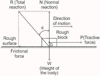
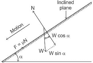
  • Force of friction or frictional force may be defined as the opposing force which is called into play in between the surfaces of contact of two bodies when one body moves over the surface of another body.

Characteristics of frictional force:
The force of friction or frictional force entails the following characteristics :

  • It is self-adjusting. As tractive force 'P' increases, the frictional force 'F' also increases, and at any instant only as much frictional force comes into play as is necessary to prevent the motion.
  • It always acts in a direction opposite to the motion (i.e., always opposes the tractive force).
  • It is a passive force (since it exists only if the tractive force P exists).

Laws of friction:
Law of static friction:

The laws of static friction are as follows :

  • The frictional force always acts in a direction opposite to that in which the body tends to move.
  • The frictional force is directly proportional to the normal reaction between the surfaces.
  • The frictional force depends upon the nature of surfaces in contact.
  • The frictional force is independent of the area and shape of the contacting surfaces. (Statement II is false)

Laws of dynamic or kinetic friction:

  • The frictional force always acts in a direction opposite to that in which the body moves.
  • The frictional force is directly proportional to the normal reaction between the two contacting surfaces.
  • The magnitude of the force of dynamic friction bears a constant ratio to the normal reaction between two surfaces but the ratio is slightly less than that in case of limiting friction.
  • The frictional force remains constant for moderate speeds but it decreases slightly with the increase in speed. (Statement I is true)

Additional Information
Static friction:

  • Static friction is the friction offered by the surfaces subjected to external forces until there is no motion between them.

Dynamic friction:

  • Dynamic friction is the friction experienced by a body when it is in motion.
  • It is also known as kinetic friction and is always less than static friction (the kinetic friction is about 40 to 75 per cent of the limiting static friction).

Limiting friction:

  • The limiting force of friction may be defined as the maximum value of friction force which exists when a body just begins to slide over the surface of the other body.
  • When the applied force or tractive force P is less than the limiting friction, the body remains at rest, and the friction is called static friction, which may have any value between zero and limiting friction.

It may be noted that :

  • For extremely low pressure and for very high pressures sufficient to produce excessive deformation, the co-efficient of static friction, somewhat increases.
  • For extremely low relative velocities, the co-efficient of kinetic friction increases and apparently becomes equal to the co-efficient of static friction.
  • For very high velocities coefficient of kinetic friction decreases appreciably.
  • Ordinary changes in temperatures do not materially affect coefficient of friction.

Co-efficient of friction:

  • It is defined as the ratio of the limiting force of friction to the normal reaction between the two bodies. It is denoted by µ.

μ = tanϕ = F/N
⇒ F = μ × N
The angle of repose:

  • The angle α is called the angle of repose and is equal to the angle of friction when the body is in the condition of limiting equilibrium on an inclined plane.

ESE (ME) Paper II Mock Test - 3 - Question 17
The main advantage of the radial drilling machine is that
Detailed Solution for ESE (ME) Paper II Mock Test - 3 - Question 17

Concept:

Advantages of radial drilling machine

  • Drill head can be moved up and down.
  • Drill head can be moved along the radial arm
  • Radial drilling machines are used for heavy job which cannot moved around easily
  • Radial drilling machines used for drilling number of holes in the job
  • Radial drilling machine is powerful machine used for drilling large diameter hole.
ESE (ME) Paper II Mock Test - 3 - Question 18

Statement (I): Capacitive proximity sensor can only be used for the detection of metal objects and is best with ferrous metals.

Statement (II): One form of capacitive proximity sensor consists of a single capacitor plate probe with the other plate being formed by the object, which has to be metallic and earthed.

Detailed Solution for ESE (ME) Paper II Mock Test - 3 - Question 18

Concept:

One form of capacitive proximity sensor consists of a single capacitor metallic and earthed figure.

As the object approaches so the 'plate separation' of the capacitor changes, becoming significant and detectable when the object is close to the probe.

Magnetic field proximity sensors are relatively simple and can be made using a permanent magnet. The magnet can be made a part of object being detected or can be part of the sensor device It can only be used for the detection of metal object and is best with ferrous metal.

ESE (ME) Paper II Mock Test - 3 - Question 19

An ideal cycle based on the concept of combination of two heat addition processes, one at constant volume and the other at constant pressure, is called

Detailed Solution for ESE (ME) Paper II Mock Test - 3 - Question 19

Concept:

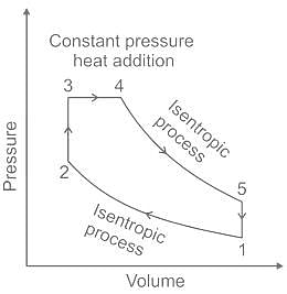
Dual cycle is a thermodynamic cycle that combines the Otto cycle and the Diesel cycle. In this cycle the heat addition occurs partly at constant volume and partly at constant pressure.

Different processes in the dual cycles are given below:

Process 1-2: Reversible adiabatic compression.

Process 2-3: Constant volume heat addition.

Process 3-4: Constant pressure heat addition.

Process 4-5: Reversible adiabatic expansion.

Process 5-1: Constant volume heat rejection.

ESE (ME) Paper II Mock Test - 3 - Question 20
In which one of the following tooth profiles, does the pressure angle remain constant throughout the engagement of teeth?
Detailed Solution for ESE (ME) Paper II Mock Test - 3 - Question 20

Concept:

Pressure angle - The angle between the pressure line and common tangent to the pitch circle is called Pressure angle or angle of obliquity.

Involute profile

It is defined as the locus of the point on the line which rolls without slipping on the fixed circle.

In involute gears, the pressure angle, from the start of the engagement of teeth to the end of the engagement, remains constant. It is necessary for smooth running and less wear of gears.

But in cycloidal gears, the pressure angle is maximum at the beginning of engagement, reduces to zero at pitch point, starts increasing and again becomes maximum at the end of engagement. This results in less smooth running of gears.

ESE (ME) Paper II Mock Test - 3 - Question 21

A compressed air spherical tank having an inner diameter of 450 mm and a wall thickness of 7 mm is formed by welding. If the allowable shear stress is 40 MPa, the maximum permissible air pressure in the tank will be nearly

Detailed Solution for ESE (ME) Paper II Mock Test - 3 - Question 21

Concept:
In a thin spherical vessel, the hoop stress and longitudinal stresses are same and are given by
σhoop = σlongitudinal = pd/4t
The maximum stress is given by τ = σ − 0/2 = pd/8t
 Calculation:
Given d = 450 mm, t = 7 mm, τ = 40 MPa;
⇒ 40 = p × 450/8 × 7
⇒ p = 4.97 MPa
The nearest option is 5 MPa

ESE (ME) Paper II Mock Test - 3 - Question 22
The phenomenon that artificially increases the dielectric constant of plastics containing fillers is known as
Detailed Solution for ESE (ME) Paper II Mock Test - 3 - Question 22

Interfacial polarization:

  • Interfacial polarization is the phenomenon caused by the presence of impurities or fillers.
  • It increases dielectric constant.
  • Interfacial or space charge polarization occurs when there is an accumulation of charge at an interface between two materials or between two regions within a material because of an external field.
  • This can occur when there is a compound dielectric, or when there are two electrodes connected to a dielectric material.
  • Under the application of applied field some of defects may migrate through the material towards two electrodes that has opposite polarity to their charge in this phenomenon.
ESE (ME) Paper II Mock Test - 3 - Question 23

What is the tip speed ratio of savonius wind turbine rotor?

Detailed Solution for ESE (ME) Paper II Mock Test - 3 - Question 23

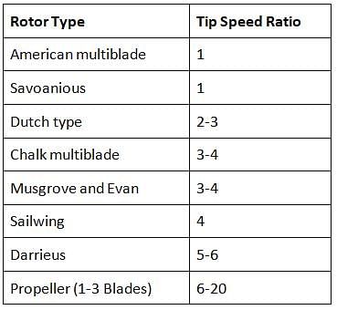
Tip Speed ratio (λ):
The tip speed ratio is given by dividing the speed of the tips of the turbine blades by the speed of the wind.


For various wind-turbine tip speed ratio is given below:

ESE (ME) Paper II Mock Test - 3 - Question 24

The efficiency of any cycle increases with

Detailed Solution for ESE (ME) Paper II Mock Test - 3 - Question 24

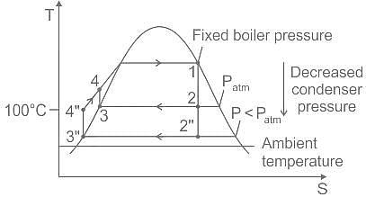
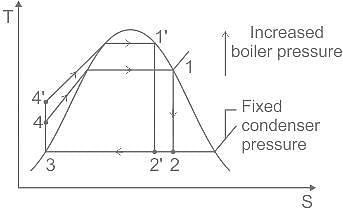
Lowering the condenser pressure:

The temperature of heat rejection for cycle 1–2–3–4–1 condensing at atmospheric pressure is 100°C. The temperature of heat rejection for the lower pressure cycle 1–2”–3”–4”–1 is correspondingly lower, so this cycle has the greater thermal efficiency.
It follows that decreasing the condenser pressure tends to increase the thermal efficiency.
Increasing the boiler pressure:

The average temperature of heat addition is seen to be greater for the higher-pressure cycle 1’–2’–3–4’–1’ than for cycle 1–2–3–4–1.
It follows that increasing the boiler pressure of the ideal Rankine cycle tends to increase the thermal efficiency.

ESE (ME) Paper II Mock Test - 3 - Question 25

The mechanical efficiency of a single-cylinder four-stroke engine is 60%. The frictional power is estimated to be 30 kW. What is the indicated power?

Detailed Solution for ESE (ME) Paper II Mock Test - 3 - Question 25

Concept:
Friction Power:
It is the power loss in overcoming the friction between piston and cylinder walls, between the crankshaft and camshaft and their bearings, etc.
It is the difference between Indicated power and Brake power.
F.P = I.P - B.P
B.P = I.P - F.P
Mechanical Efficiency:

It is the ratio of brake power to indicated power.
ηm = B.P/I.P = ηbthith
Calculation:
Given:
ηm = 60% = 0.6, FP = 30 kW
Mechanical Efficiency:
ηm = B.P/I.P
ηm = I.P − F.P/I.P
0.6 = I.P − 30/I.P
I.P - 0.6I.P = 30
0.4I.P = 30
I.P = 75 kW

ESE (ME) Paper II Mock Test - 3 - Question 26

Consider the following statements for stress and strain analysis :

1. The stress components on any inclined plane can easily be found with the help of a geometrical construction known as Mohr’s stress circle.

2. The ratio of longitudinal strain to lateral strain is known as Poisson’s ratio.

3. When a body is acted upon by three mutually perpendicular forces, there is change in the volume of the body which is referred to as dilation of the material.

4. The ratio of original volume to increase in volume is known as volumetric strain.

Which of the above statements are correct ?

Detailed Solution for ESE (ME) Paper II Mock Test - 3 - Question 26

Mohr Circle:

  • It is a two-dimensional graphical representation (σ as x-axis and τ as y-axis) of the state of stress inside a body.
  • The abscissa and ordinate of each point on the circle are the magnitudes of the normal stress and shear stress components, respectively.
  • In other words, the Mohr circle is the locus of those points which represents the normal and shear stress on various planes passing through a point on a loaded body.

Poisson ratio:
Poisson's ratio is the ratio of lateral strain to longitudinal strain.

Dilation:

  • Strain in each direction (or, each component of strain) depends on the normal stress in that direction, and the Poisson's ratio times the strain in the other two directions.
  • If an object changes shape in all three directions, that means it will change its volume. A simple measure for this volume change can be found by adding up the three normal components of strain.
  • A very common type of stress that causes dilation is known as hydrostatic stress which is just simply a pressure that acts equally on the entire material.

Volumetric strain:

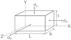
When a rectangular prismatic member subjected to stresses (σx, σy, σz) in three mutually perpendicular axis, then the volumetric strain is given by:

It is also the ratio of change in volume by original volume.

ESE (ME) Paper II Mock Test - 3 - Question 27

The TTT diagram shows the times required for isothermal transition from

Detailed Solution for ESE (ME) Paper II Mock Test - 3 - Question 27
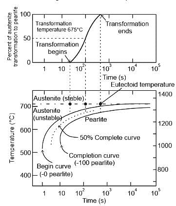
  • The TTT diagram shows the times required for isothermal transition from austenite to pearlite

  • In interpreting this diagram, note first that the eutectoid temperature 727°C is indicated by a horizontal line, at temperatures above the eutectoid and for all times, only austenite exists, as indicated in the figure.
  • The austenite-to-pearlite transformation occurs only if an alloy is supercooled to below the eutectoid, as indicated by the curves, the time necessary for the transformation to begin and then end depends on temperature.
  • The start and finish curves are nearly parallel, and they approach the eutectoid line asymptotically.
  • To the left of the transformation start curve, only austenite (which is unstable) is present, whereas to the right of the finish curve, only pearlite exists.
  • In between, the austenite is in the process s of transforming to pearlite, and thus both microconstituents are present.
ESE (ME) Paper II Mock Test - 3 - Question 28

According to maximum shear stress theory, with comparison to yield strength in tension, the yield strength in shear is

Detailed Solution for ESE (ME) Paper II Mock Test - 3 - Question 28

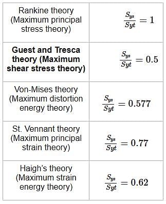
The following chart shows the ratio of shear yield stress to the tensile yield stress

ESE (ME) Paper II Mock Test - 3 - Question 29

A cast steel bar having an ultimate strength of 120 MPa is subjected to a reversed, repeated, bending load. The bar will be machined to a rectangular cross-section, 150 mm wide × 200 mm high. What is the equivalent diameter?

Detailed Solution for ESE (ME) Paper II Mock Test - 3 - Question 29

Concept:
The 'effective' diameter of any non-circular cross-section is then given by:


where, A95 = portion of the cross-sectional area of the non-cylindrical part that is stressed between 95% and 100% of the maximum stress, de = effective diameter of the non-cylindrical part.
For a rectangular cross-section having width b and depth h:
A95 = 0.05bh
where b = width and h = height
Calculation:
Given:
b = 150 mm, h = 200 mm

and A95 = 0.05bh
deq = 0.808√bh
deq = 0.808√150 × 200
deq = 140 mm

ESE (ME) Paper II Mock Test - 3 - Question 30

Which one of the following contains design data on all products, e.g., their constituent components and parts ?

Detailed Solution for ESE (ME) Paper II Mock Test - 3 - Question 30

Engineering data master file:

  • A material planning and control system based on Material Requirements Planning (MRP) database uses several key computer files and one such file is the Engineering data master file which contains design data of products and their constituents component and parts.
  • Two files are commonly used to store part-related data. Some data concerning parts will remain the same, or very similar, from period to period, and these data are stored in the Item Master File.
  • Information on part status, which is more dynamic, is stored in the Subordinate Item Master File.
  • The item master file contains all the static data necessary to give a complete description of each part.
  • The data in the item master file are used for MRP, purchasing, costing, and so on.
  • The data on each consist of part number, part name, low-level code, unit of measure, engineering change number, drawing reference, release date, planner code, order policy code, lead time, safety stock, standard costs, and links to routing and bill of material (BOM) files.
  • The subordinate item master file contains data pertaining to current shop order numbers, time-phased scheduled..
View more questions
Information about ESE (ME) Paper II Mock Test - 3 Page
In this test you can find the Exam questions for ESE (ME) Paper II Mock Test - 3 solved & explained in the simplest way possible. Besides giving Questions and answers for ESE (ME) Paper II Mock Test - 3, EduRev gives you an ample number of Online tests for practice

Top Courses for Mechanical Engineering

Download as PDF

Top Courses for Mechanical Engineering