Mechanical Engineering Exam  >  Mechanical Engineering Tests  >  Test: Bending Moment & Shear Force Diagram - 1 - Mechanical Engineering MCQ

Test: Bending Moment & Shear Force Diagram - 1 - Mechanical Engineering MCQ


Test Description

20 Questions MCQ Test - Test: Bending Moment & Shear Force Diagram - 1

Test: Bending Moment & Shear Force Diagram - 1 for Mechanical Engineering 2024 is part of Mechanical Engineering preparation. The Test: Bending Moment & Shear Force Diagram - 1 questions and answers have been prepared according to the Mechanical Engineering exam syllabus.The Test: Bending Moment & Shear Force Diagram - 1 MCQs are made for Mechanical Engineering 2024 Exam. Find important definitions, questions, notes, meanings, examples, exercises, MCQs and online tests for Test: Bending Moment & Shear Force Diagram - 1 below.
Solutions of Test: Bending Moment & Shear Force Diagram - 1 questions in English are available as part of our course for Mechanical Engineering & Test: Bending Moment & Shear Force Diagram - 1 solutions in Hindi for Mechanical Engineering course. Download more important topics, notes, lectures and mock test series for Mechanical Engineering Exam by signing up for free. Attempt Test: Bending Moment & Shear Force Diagram - 1 | 20 questions in 60 minutes | Mock test for Mechanical Engineering preparation | Free important questions MCQ to study for Mechanical Engineering Exam | Download free PDF with solutions
Test: Bending Moment & Shear Force Diagram - 1 - Question 1

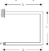
A concentrated force, F is applied (perpendicular to the plane of the figure) on the tip of the bent bar shown in Figure. The equivalent load at a section close to the fixed end is:
Test: Bending Moment & Shear Force Diagram - 1 - Question 2

Two identical cantilever beams are supported as shown, with their free ends in contact through a rigid roller. After the load P is applied, the free ends will have

Detailed Solution for Test: Bending Moment & Shear Force Diagram - 1 - Question 2

As it is rigid roller, deflection must be same, because after deflection they also will be in contact. But slope unequal.

1 Crore+ students have signed up on EduRev. Have you? Download the App
Test: Bending Moment & Shear Force Diagram - 1 - Question 3

A mass less beam has a loading pattern as shown in the figure. The beam is of rectangular cross -section with a width of 30 mm and height of 100 mm.
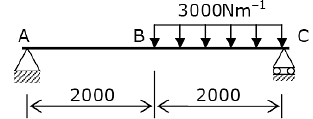
The maximum magnitude of bending stress (in MPa) is given by

Detailed Solution for Test: Bending Moment & Shear Force Diagram - 1 - Question 3


Test: Bending Moment & Shear Force Diagram - 1 - Question 4

The shapes of the bending moment diagram for a uniform cantilever beam carrying a uniformly distributed load over its length is:

Detailed Solution for Test: Bending Moment & Shear Force Diagram - 1 - Question 4

Test: Bending Moment & Shear Force Diagram - 1 - Question 5

Solve the problems and choose correct answers A steel beam of breadth 120 mm and height 750 mm is loaded as shown in the figure. Assume Esteel= 200 GPa.

The beam is subjected to a maximum bending moment of

Detailed Solution for Test: Bending Moment & Shear Force Diagram - 1 - Question 5

Test: Bending Moment & Shear Force Diagram - 1 - Question 6

A simply supported beam of span length 6m and 75mm diameter carries a uniformly distributed load of 1.5 kN/m

What is the maximum value of bending moment?

Detailed Solution for Test: Bending Moment & Shear Force Diagram - 1 - Question 6

Test: Bending Moment & Shear Force Diagram - 1 - Question 7

A simply supported beam is subjected to a distributed loading as shown in the diagram given below:

What is the maximum shear force in the beam?

Detailed Solution for Test: Bending Moment & Shear Force Diagram - 1 - Question 7

Test: Bending Moment & Shear Force Diagram - 1 - Question 8

A lever is supported on two hinges at A and C. It carries a force of 3 kN as shown in the above figure. The bending moment at B will be

Test: Bending Moment & Shear Force Diagram - 1 - Question 9

The bending moment (M) is constant over a length segment (I) of a beam. The shearing force will also be constant over this length and is given by

Detailed Solution for Test: Bending Moment & Shear Force Diagram - 1 - Question 9

Correct Option is A. 
None of these

Test: Bending Moment & Shear Force Diagram - 1 - Question 10

Consider the following statements:

If at a section distant from one of the ends of the beam, M represents the bending moment. V the shear force and w the intensity of loading, then

1. dM/dx = V

2. dV/dx = w      

3. dw/dx = y

(the deflection of the beam at the section)

Select the correct answer using the codes given below:

Test: Bending Moment & Shear Force Diagram - 1 - Question 11

If the shear force acting at every section of a beam is of the same magnitude and of the same direction then it represents a

Test: Bending Moment & Shear Force Diagram - 1 - Question 12

The shearing force diagram for a beam is shown in the above figure. The bending moment diagram is represented by which one of the following?

Detailed Solution for Test: Bending Moment & Shear Force Diagram - 1 - Question 12

Uniformly distributed load on cantilever beam.

Test: Bending Moment & Shear Force Diagram - 1 - Question 13

A vertical hanging bar of length L and weighing w N/ unit length carries a load W at the bottom. The tensile force in the bar at a distance Y from the support will be given by

Test: Bending Moment & Shear Force Diagram - 1 - Question 14

Assertion (A): If the bending moment along the length of a beam is constant, then the beam cross section will not experience any shear stress.

Reason (R): The shear force acting on the beam will be zero everywhere along the length.

Test: Bending Moment & Shear Force Diagram - 1 - Question 15

What is the bending moment at end supports of a simply supported beam?

Detailed Solution for Test: Bending Moment & Shear Force Diagram - 1 - Question 15

At the end supports, the moment (couple) developed is zero, because there is no distance to take the perpendicular acting load. As the distance is zero, the moment is obviously zero.

Test: Bending Moment & Shear Force Diagram - 1 - Question 16

If a beam is subjected to a constant bending moment along its length, then the shear force will

Detailed Solution for Test: Bending Moment & Shear Force Diagram - 1 - Question 16

The relation between shear force (V) and bending moment (M) is:

it means the slope of a bending moment diagram will represent the magnitude of shear force at that section.

Since the bending moment is constant along the length, therefore its derivative i.e. shear force is equal to zero at all sections along the beam.

There is no shear force between the loads and the bending moment is constant for that section along the length and vice-versa.

Test: Bending Moment & Shear Force Diagram - 1 - Question 17

A simply supported beam has equal over-hanging lengths and carries equal concentrated loads P at ends. Bending moment over the length between the supports

Test: Bending Moment & Shear Force Diagram - 1 - Question 18

Which one of the following portions of the loaded beam shown in the given figure is subjected to pure bending?

Detailed Solution for Test: Bending Moment & Shear Force Diagram - 1 - Question 18

Pure bending takes place in the section between two weights W

Test: Bending Moment & Shear Force Diagram - 1 - Question 19

 At the point of contraflexure, the value of bending moment is____

Detailed Solution for Test: Bending Moment & Shear Force Diagram - 1 - Question 19

A point at which bending moment changes its sign from positive to negative and vice versa. Such point is termed as point of contraflexure. At this point, the value of bending moment is zero (0).

Test: Bending Moment & Shear Force Diagram - 1 - Question 20

A freely supported beam at its ends carries a central concentrated load, and maximum bending moment is M. If the same load be uniformly distributed over the beam length, then what is the maximum bending moment?

Detailed Solution for Test: Bending Moment & Shear Force Diagram - 1 - Question 20

Information about Test: Bending Moment & Shear Force Diagram - 1 Page
In this test you can find the Exam questions for Test: Bending Moment & Shear Force Diagram - 1 solved & explained in the simplest way possible. Besides giving Questions and answers for Test: Bending Moment & Shear Force Diagram - 1, EduRev gives you an ample number of Online tests for practice

Top Courses for Mechanical Engineering

Download as PDF

Top Courses for Mechanical Engineering