


All Exams > Electrical Engineering (EE) > 6 Months Preparation for GATE Electrical > All Questions
All questions of Network Theorems for Electrical Engineering (EE) Exam
In source transformation________- a)Voltage source remain the same
- b)Current sources remain the same
- c)Both voltage and current source remain the same
- d)Resistances remain the same
Correct answer is option 'D'. Can you explain this answer?
In source transformation________
a)
Voltage source remain the same
b)
Current sources remain the same
c)
Both voltage and current source remain the same
d)
Resistances remain the same
| | Sanchita Sharma answered |
In source transformation, the value of the voltage and current sources change when changed from voltage to current source and current to voltage source but the value of the resistances remains the same.

Calculate the total current in the circuit.

- a) 2.3mA
- b)4.3mA
- c)3.3mA
- d)1.3mA
Correct answer is option 'C'. Can you explain this answer?
Calculate the total current in the circuit.
a)
2.3mA
b)
4.3mA
c)
3.3mA
d)
1.3mA
 | Gate Funda answered |
The 9mA source connected in parallel to the 5 kohm resistor can be converted to a 45V source in series with a 5 kohm resistor. Applying mesh analysis, we get:
I=(45-3)/(5+4.7+3)= 3.3mA.
I=(45-3)/(5+4.7+3)= 3.3mA.
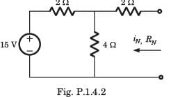
iN, RN, = ?
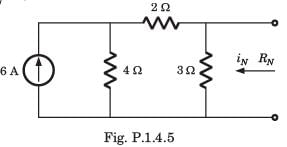
- a)4A,3 Ω
- b)2A, 6Ω
- c)2A, 9Ω
- d)4A, 2Ω
Correct answer is option 'D'. Can you explain this answer?
iN, RN, = ?
a)
4A,3 Ω
b)
2A, 6Ω
c)
2A, 9Ω
d)
4A, 2Ω
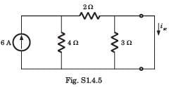
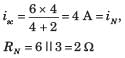
| | Luminary Institute answered |
The short circuit current across the terminal is
Which among the following theorems can be applied to any active or passive network?- a)Thevenin’s theorem
- b)Tellegen theorem
- c)Superposition theorem
- d)Norton theorem
Correct answer is option 'B'. Can you explain this answer?
Which among the following theorems can be applied to any active or passive network?
a)
Thevenin’s theorem
b)
Tellegen theorem
c)
Superposition theorem
d)
Norton theorem
 | Pioneer Academy answered |
Tellegen theorem can be applied to any network- linear or non-linear, active or passive, time-variant, or time-invariant.
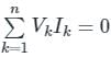
Tellegen Theorem: According to Tellegen’s theorem, the summation of instantaneous powers for the n number of branches in an electrical network is zero.
Let n number of branches in an electrical network have I1, I2, I3, …. In respective instantaneous currents through them.
These branches have instantaneous voltages across them are V1, V2, V3, …. Vn respectively.
According to Tellegen’s theorem:
It is based on the conservation of energy and is applicable to both linear and non-linear circuits.
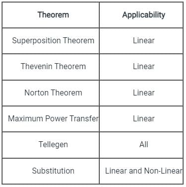
Important Notes:
Various Theorem and the circuits where they are applicable is shown below in the table:
Tellegen Theorem: According to Tellegen’s theorem, the summation of instantaneous powers for the n number of branches in an electrical network is zero.
Let n number of branches in an electrical network have I1, I2, I3, …. In respective instantaneous currents through them.
These branches have instantaneous voltages across them are V1, V2, V3, …. Vn respectively.
According to Tellegen’s theorem:
It is based on the conservation of energy and is applicable to both linear and non-linear circuits.
Important Notes:
Various Theorem and the circuits where they are applicable is shown below in the table:
Calculate the value of RL across A and B.
- a)3.45ohm
- b)2.91ohm
- c)6.34ohm
- d)1.54ohm
Correct answer is option 'B'. Can you explain this answer?
Calculate the value of RL across A and B.
a)
3.45ohm
b)
2.91ohm
c)
6.34ohm
d)
1.54ohm
| | Sakshi Tiwari answered |
On shorting the voltage sources:
RL=3||2+4||5.
RL=3||2+4||5.
A current source connected in parallel with a resistor can be converted to a?- a)Current source in series with a resistor
- b)Voltage source in series with a resistor
- c)Voltage source in parallel with a resistor
- d)Cannot be modified
Correct answer is option 'B'. Can you explain this answer?
A current source connected in parallel with a resistor can be converted to a?
a)
Current source in series with a resistor
b)
Voltage source in series with a resistor
c)
Voltage source in parallel with a resistor
d)
Cannot be modified
| | Ritika Sarkar answered |
A current source connected in parallel can be converted to a voltage source connected in series using the relation obtained from ohm’s law, that is V=IR. This equation shows that a current source connected in parallel has the same impact as a voltage source connected in series.
A battery has a short-circuit current of 30 A and an open circuit voltage of 24 V. If the battery is connected to an electric bulb of resistance 2 Ω, the power dissipated by the bulb is- a)80 W
- b)1800 W
- c)146.93 W
- d)228 W
Correct answer is option 'C'. Can you explain this answer?
A battery has a short-circuit current of 30 A and an open circuit voltage of 24 V. If the battery is connected to an electric bulb of resistance 2 Ω, the power dissipated by the bulb is
a)
80 W
b)
1800 W
c)
146.93 W
d)
228 W
| | Ravi Singh answered |
 0.8
0.8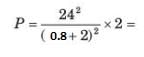 146.93
Vth is found across the ____________ terminals of the network.- a)Input
- b)Output
- c)Neither input nor output
- d)Either input or output
Correct answer is option 'B'. Can you explain this answer?
Vth is found across the ____________ terminals of the network.
a)
Input
b)
Output
c)
Neither input nor output
d)
Either input or output
| | Ravi Singh answered |
According to Thevenin’s theorem, Vth is found across the output terminals of a network and not the input terminals.
Isc is found across the ____________ terminals of the network.- a)Input
- b)Output
- c)Neither input nor output
- d)Either input or output
Correct answer is option 'B'. Can you explain this answer?
Isc is found across the ____________ terminals of the network.
a)
Input
b)
Output
c)
Neither input nor output
d)
Either input or output
 | Ravikumar Pasula answered |
Short circuit current will be calculated at output terminal of the network by the theorem of northern
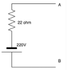
What will the value of the current be once source transformation is applied to the circuit?
- a)10A
- b)20A
- c)30A
- d)40A
Correct answer is option 'A'. Can you explain this answer?
What will the value of the current be once source transformation is applied to the circuit?
a)
10A
b)
20A
c)
30A
d)
40A
| | Rhea Reddy answered |
Using ohm’s law, we can use the relation: V=IR.
Thus I=V/R.
I=220/22=10A.
Thus I=V/R.
I=220/22=10A.
In Thevenin’s theorem Vth is__________- a)Sum of two voltage sources
- b)A single voltage source
- c)Infinite voltage sources
- d)0
Correct answer is option 'B'. Can you explain this answer?
In Thevenin’s theorem Vth is__________
a)
Sum of two voltage sources
b)
A single voltage source
c)
Infinite voltage sources
d)
0
| | Sneha Bose answered |
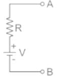
Thevenin’s theorem states that a combination of voltage sources, current sources and resistors is equivalent to a single voltage source V and a single series resistor R.
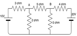
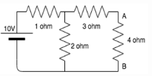
Calculate the current across the 4 ohm resistor.
- a)0.86A
- b)1.23A
- c)2.22A
- d)0.67A
Correct answer is option 'A'. Can you explain this answer?
Calculate the current across the 4 ohm resistor.
a)
0.86A
b)
1.23A
c)
2.22A
d)
0.67A
| | Anirban Gupta answered |
Thevenin resistance is found by opening the circuit between the specified terminal and shorting all voltage sources.
When the 10V source is shorted, we get:
Rth=(1||2)+3=3.67 ohm.
Vth is calculated by opening the specified terminal.
Using voltage divider, Vth= 2*10/(2+1)=6.67V.
On drawing the Thevenin equivalent circuit, we get Rth, 4 ohm and Vth in series.
Applying ohm’s law, I=Vth/(4+Rth)= 0.86A.
When the 10V source is shorted, we get:
Rth=(1||2)+3=3.67 ohm.
Vth is calculated by opening the specified terminal.
Using voltage divider, Vth= 2*10/(2+1)=6.67V.
On drawing the Thevenin equivalent circuit, we get Rth, 4 ohm and Vth in series.
Applying ohm’s law, I=Vth/(4+Rth)= 0.86A.
What does Millman’s theorem yield?- a)Equivalent voltage source
- b)Equivalent resistance
- c)Equivalent admittance
- d)Equivalent impedance
Correct answer is option 'A'. Can you explain this answer?
What does Millman’s theorem yield?
a)
Equivalent voltage source
b)
Equivalent resistance
c)
Equivalent admittance
d)
Equivalent impedance
| | Niti Tiwari answered |
Millman's Theorem
Millman's theorem is a circuit analysis technique that allows the combination of multiple voltage sources in parallel with their internal resistances into a single equivalent voltage source. This equivalent voltage source is calculated by taking the weighted sum of the individual voltage sources based on their respective internal resistances.
Yield of Millman's Theorem
- Equivalent voltage source: Millman's theorem yields an equivalent voltage source that represents the combined effect of multiple voltage sources in parallel. This equivalent voltage source simplifies the circuit analysis by reducing the circuit to a single voltage source.
- Equivalent resistance, admittance, and impedance are not directly calculated using Millman's theorem. The focus is on determining the equivalent voltage source.
Using Millman's theorem, one can simplify complex circuits with multiple voltage sources in parallel into a more manageable form for analysis. This simplification aids in understanding the behavior of the circuit and helps in calculating the desired electrical parameters.
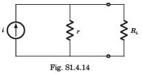
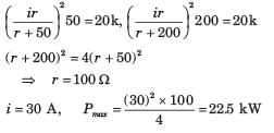
A voltage source having some internal resistance delivers a 2A current when a 5Ω load is connected to it. When the load is 10Ω, then the current becomes 1.6A. Calculate the power transfer efficiency of the source for a 15Ω load.- a)90%
- b)50%
- c)100%
- d)10%
Correct answer is option 'B'. Can you explain this answer?
A voltage source having some internal resistance delivers a 2A current when a 5Ω load is connected to it. When the load is 10Ω, then the current becomes 1.6A. Calculate the power transfer efficiency of the source for a 15Ω load.
a)
90%
b)
50%
c)
100%
d)
10%
 | Telecom Tuners answered |
To determine the power transfer efficiency of the voltage source when a 15Ω load is connected, we need to understand the behavior of the circuit, which includes a voltage source with internal resistance.
First, define the voltage across the source as V and the internal resistance as R. Two scenarios are given:
Scenario 1: When a 5Ω load is connected, the current I is 2A. The voltage equation is: V = 2(5 + R)
Scenario 2: With a 10Ω load, the current is 1.6A, giving the equation: V = 1.6(10 + R)
First, define the voltage across the source as V and the internal resistance as R. Two scenarios are given:
Scenario 1: When a 5Ω load is connected, the current I is 2A. The voltage equation is: V = 2(5 + R)
Scenario 2: With a 10Ω load, the current is 1.6A, giving the equation: V = 1.6(10 + R)
.
Now, for a 15Ω load, calculate the current:
Using the formula I = V / (R + Load)Substitute the values: I = 40/(15 + 15) = 40/30 = 4/3 A
Using 2(5 + 15) = V, we find V = 40 volts
Substituting R back into one of the original equations gives the voltage V:
By solving these equations simultaneously:
From 2(5 + R) = 1.6(10 + R), expand and simplify to obtain:
10 + 2R = 16 + 1.6R
Simplifying further: 0.4R = 6
Thus, R = 15Ω
10 + 2R = 16 + 1.6R
Simplifying further: 0.4R = 6
Thus, R = 15Ω
Calculate the efficiency of power transfer to the load:
The power delivered to the load is: PL = (4/3)^2 * 15
The total power from the source: Ptotal = 40 * 4/3
Efficiency η is calculated as: η = (PL / Ptotal) * 100%
The total power from the source: Ptotal = 40 * 4/3
Efficiency η is calculated as: η = (PL / Ptotal) * 100%
Thus, η = ((4/3 * 15) / 40) * 100% = 50%
The correct answer is 50%, indicating that with a 15Ω load, 50% of the power is efficiently transferred from the source to the load
A voltage source connected in series with a resistor can be converted to a?- a)Current source in series with a resistor
- b)Current source in parallel with a resistor
- c)Voltage source in parallel with a resistor
- d)Cannot be modified
Correct answer is option 'B'. Can you explain this answer?
A voltage source connected in series with a resistor can be converted to a?
a)
Current source in series with a resistor
b)
Current source in parallel with a resistor
c)
Voltage source in parallel with a resistor
d)
Cannot be modified
| | Arpita Banerjee answered |
A voltage source connected in series can be converted to a current source connected in parallel using the relation obtained from ohm’s law, that is V=IR. This equation shows that a voltage source connected in series has the same impact as a current source connected in parallel.
Using Millman’s theorem, find the current through the load resistance, RL of 2 Ω resistance shown below:
- a)2 A
- b)4 A
- c)3 A
- d)6 A
Correct answer is option 'A'. Can you explain this answer?
Using Millman’s theorem, find the current through the load resistance, RL of 2 Ω resistance shown below:
a)
2 A
b)
4 A
c)
3 A
d)
6 A
 | Cstoppers Instructors answered |
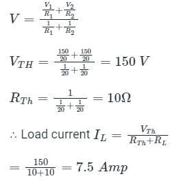
It is states that – when a number of voltage sources (V1, V2, V3……… Vn) are in parallel having internal resistance (R1, R2, R3………….Rn) respectively, the arrangement can replace by a single equivalent voltage source V in series with an equivalent series resistance R.
The equivalent circuit parameter
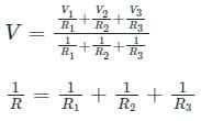
V = equivalent voltage
R = equivalent resistance
Calculation:
From Millman's theorem, the above circuit can be redrawn as
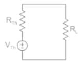
where
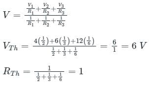
∴ Load current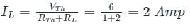
The equivalent circuit parameter
V = equivalent voltage
R = equivalent resistance
Calculation:
From Millman's theorem, the above circuit can be redrawn as
where
∴ Load current
In superposition theorem, when we consider the effect of one current source, all the other voltage sources are____________- a)Shorted
- b)Opened
- c)Removed
- d)Undisturbed
Correct answer is option 'A'. Can you explain this answer?
In superposition theorem, when we consider the effect of one current source, all the other voltage sources are____________
a)
Shorted
b)
Opened
c)
Removed
d)
Undisturbed
| | Palak Verma answered |
In superposition theorem, whether we consider the effect of a voltage or current source, voltage sources are always shorted and current sources are always opened.
The theorem which states that in any linear, non-linear, passive, active, time-variant and time-invariant network, the summation of instantaneous powers is zero will be called as- a)Tellegen’s theorem
- b)Compensation theorem
- c)reciprocity theorem
- d)superposition theorem
Correct answer is option 'A'. Can you explain this answer?
The theorem which states that in any linear, non-linear, passive, active, time-variant and time-invariant network, the summation of instantaneous powers is zero will be called as
a)
Tellegen’s theorem
b)
Compensation theorem
c)
reciprocity theorem
d)
superposition theorem
| | Divya Nair answered |
Explanation:
Tellegen's Theorem:
Tellegen's theorem states that in any linear or non-linear, passive or active, time-variant or time-invariant network, the algebraic sum of instantaneous powers at any instant in time is always zero.
Key Points:
- The theorem is named after Bernard Tellegen, a Dutch electrical engineer.
- It is a fundamental principle in electrical engineering and is used to analyze and understand the power flow in a network.
- The theorem is based on the conservation of energy principle, stating that the total power entering a network at any instant must be equal to the total power leaving the network.
- Tellegen's theorem can be applied to both AC and DC circuits, making it a versatile tool in circuit analysis.
- The theorem is essential for power system analysis, as it helps in determining power losses and optimizing the efficiency of electrical networks.
- Tellegen's theorem is used in various applications, including power distribution systems, signal processing, and electronic circuit design.
Conclusion:
Tellegen's theorem is a powerful tool in circuit analysis that helps in understanding and analyzing power flow in electrical networks. It is a fundamental principle that applies to a wide range of networks and is essential for engineers working in the field of electrical engineering.
Reciprocity theorem cannot be applied to the circuits having ______.- a)Linear elements
- b)Dependent sources
- c)Bilateral elements
- d)Passive elements
Correct answer is option 'B'. Can you explain this answer?
Reciprocity theorem cannot be applied to the circuits having ______.
a)
Linear elements
b)
Dependent sources
c)
Bilateral elements
d)
Passive elements
| | Pankaj Mehta answered |
Reciprocity theorem in circuit theory states that when a source voltage is applied to one part of a linear bilateral network, the resulting current at another part of the network due to this voltage source will be the same as the current that would be produced by applying the same source voltage to the second part of the network while keeping the first part open-circuited.
Explanation:
Reciprocity theorem is a fundamental principle in circuit theory that allows us to simplify circuit analysis by interchanging the roles of sources and loads. However, there are certain conditions that need to be met for the reciprocity theorem to be applicable. In this case, the correct answer is option B, i.e., dependent sources.
Dependent sources are circuit elements whose values depend on some other circuit variables, such as voltage or current. These sources are not constant and can change their values based on the conditions in the circuit. Due to this dependency, the reciprocity theorem cannot be applied to circuits that contain dependent sources.
Dependent sources introduce a level of complexity in the circuit analysis because their values are not known or fixed. The reciprocity theorem assumes that the circuit elements are linear and bilateral, meaning that their behavior is independent of the direction of current flow. However, dependent sources violate this assumption as their behavior depends on the values of other circuit variables.
In contrast, linear elements such as resistors, capacitors, and inductors have a fixed relationship between voltage and current and do not introduce any dependency. Bilateral elements, on the other hand, exhibit the same behavior regardless of the direction of current flow. These characteristics make linear and bilateral elements suitable for the application of the reciprocity theorem.
In conclusion, the reciprocity theorem cannot be applied to circuits containing dependent sources because these sources introduce a level of complexity and violate the assumptions of linearity and bilateral behavior.
Thevenin’s theorem is true for __________- a)Linear networks
- b)Non-Linear networks
- c)Both linear networks and nonlinear networks
- d)Neither linear networks nor non-linear networks
Correct answer is option 'A'. Can you explain this answer?
Thevenin’s theorem is true for __________
a)
Linear networks
b)
Non-Linear networks
c)
Both linear networks and nonlinear networks
d)
Neither linear networks nor non-linear networks
| | Prisha Sengupta answered |
Thevenin’s theorem works for only linear circuit elements and not non-linear ones such as BJT, semiconductors etc.
Name some devices where maximum power has to be transferred to the load rather than maximum efficiency.- a)Amplifiers
- b)Communication circuits
- c)Both amplifiers and communication circuits
- d)Neither amplifiers nor communication circuits
Correct answer is option 'C'. Can you explain this answer?
Name some devices where maximum power has to be transferred to the load rather than maximum efficiency.
a)
Amplifiers
b)
Communication circuits
c)
Both amplifiers and communication circuits
d)
Neither amplifiers nor communication circuits
| | Upasana Joshi answered |
Maximum power transfer to the load is preferred over maximum efficiency in both amplifiers and communication circuits since in both these cases the output voltage is more than the input.
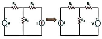
Consider the two-port resistive network shown in the figure. When an excitation of 5 V is applied across Port 1, and Port 2 is shorted, the current through the short circuit at Port 2 is measured to be 1 A (see (a) in the figure).Now, if an excitation of 5 V is applied across Port 2, and Port 1 is shorted (see (b) in the figure), what is the current through the short circuit at Port 1?
- a)0.5 A
- b)1 A
- c)2 A
- d)2.5 A
Correct answer is option 'B'. Can you explain this answer?
Consider the two-port resistive network shown in the figure. When an excitation of 5 V is applied across Port 1, and Port 2 is shorted, the current through the short circuit at Port 2 is measured to be 1 A (see (a) in the figure).
Now, if an excitation of 5 V is applied across Port 2, and Port 1 is shorted (see (b) in the figure), what is the current through the short circuit at Port 1?
a)
0.5 A
b)
1 A
c)
2 A
d)
2.5 A
| | Pooja Patel answered |
Reciprocity Theorem:
In any passive linear bilateral network, if a single voltage source ‘V’ in the branch AB produces the current response ‘I’ in the branch CD, then the removal of voltage source from the branch AB and its insertion in the branch CD will produce same current ‘I’ in the branch AB.
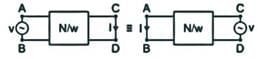
In the reciprocity theorem, if the position of excitation and responses are interchanged, then their ratio remains the same.

Application:

I2 = 1 A
In any passive linear bilateral network, if a single voltage source ‘V’ in the branch AB produces the current response ‘I’ in the branch CD, then the removal of voltage source from the branch AB and its insertion in the branch CD will produce same current ‘I’ in the branch AB.
In the reciprocity theorem, if the position of excitation and responses are interchanged, then their ratio remains the same.
Application:
I2 = 1 A
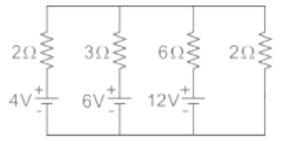
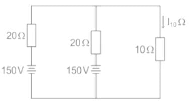
In the circuit shown below, the current through 10Ω resistor is:
- a)5 A
- b)10 A
- c)-5 A
- d)None of these
Correct answer is option 'D'. Can you explain this answer?
In the circuit shown below, the current through 10Ω resistor is:
a)
5 A
b)
10 A
c)
-5 A
d)
None of these
| | Pooja Patel answered |
Concept:
Millman’s Theorem:
It is stated that – when a number of voltage sources (V1, V2, V3……… Vn) are in parallel having internal resistance (R1, R2, R3………….Rn) respectively, the arrangement can replace by a single equivalent voltage source V in series with an equivalent series resistance R.
The equivalent circuit parameter
V = equivalent voltage
R = equivalent resistance
Calculation:
From Millman's theorem, the above circuit can be redrawn as
Where
Can we use Thevinin’s theorem on a circuit containing a BJT?- a)Yes
- b)No
- c)Depends on the BJT
- d)Insufficient data provided
Correct answer is option 'B'. Can you explain this answer?
Can we use Thevinin’s theorem on a circuit containing a BJT?
a)
Yes
b)
No
c)
Depends on the BJT
d)
Insufficient data provided
| | Sandeep Saha answered |
We can use Thevenin’s theorem only for linear networks. BJT is a non-linear network hence we cannot apply Thevenin’s theorem for it.
What is the current I corresponding to the terminal conditions as shown in the figure below.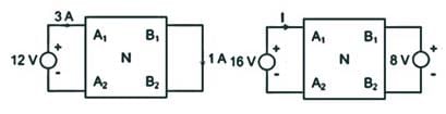
- a)4 A
- b)8.33 A
- c)4.66 A
- d)2.33 A
Correct answer is option 'C'. Can you explain this answer?
What is the current I corresponding to the terminal conditions as shown in the figure below.
a)
4 A
b)
8.33 A
c)
4.66 A
d)
2.33 A
| | Pioneer Academy answered |
The current I1 due to 16 V source only
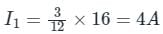
The current I2 due to 8 V source is,
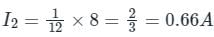
Total current:-
(4 + 0.66) = 4.66 A
The current I2 due to 8 V source is,
Total current:-
(4 + 0.66) = 4.66 A
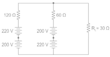
In the circuit shown above, the current through RL is- a)6 A
- b)4 A
- c)2 A
- d)0
Correct answer is option 'A'. Can you explain this answer?
In the circuit shown above, the current through RL is
a)
6 A
b)
4 A
c)
2 A
d)
0
| | Pooja Patel answered |
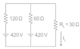
Applying Millman's theorem we get
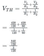
= 420 V
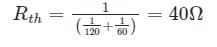
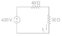
IL = 420/70
= 6 A
Which of the following theorem can be applied to any network-linear or non-linear, active or passive, time-variant or time-invariant?- a)Thevenin Theorem
- b)Norton Theorem
- c)Superposition Theorem
- d)Tellegen’s Theorem
Correct answer is option 'D'. Can you explain this answer?
Which of the following theorem can be applied to any network-linear or non-linear, active or passive, time-variant or time-invariant?
a)
Thevenin Theorem
b)
Norton Theorem
c)
Superposition Theorem
d)
Tellegen’s Theorem
| | Arindam Sengupta answered |
The Superposition Theorem can be applied to any network-linear or non-linear, active or passive, time-variant or time-invariant.
Reciprocity theorem is applicable to a network
1. Containing R, L and C elements
2. Which is initially not a relaxed system
3. Having both dependent and independent sourcesWhich of the above is/are correct?- a)1 only
- b)1 and 2 only
- c)2 and 3 only
- d)1, 2 and 3
Correct answer is option 'A'. Can you explain this answer?
Reciprocity theorem is applicable to a network
1. Containing R, L and C elements
2. Which is initially not a relaxed system
3. Having both dependent and independent sources
1. Containing R, L and C elements
2. Which is initially not a relaxed system
3. Having both dependent and independent sources
Which of the above is/are correct?
a)
1 only
b)
1 and 2 only
c)
2 and 3 only
d)
1, 2 and 3
| | Pooja Patel answered |
Reciprocity theorem: It states that the current I in any branch of a network, due to single voltage source (E) anywhere in the network is equal to the current of the branch in which source was placed originally and when the source is again put in the branch in which current is obtained originally.
Limitations of reciprocity theorem:
- The network should be linear and time-invariant
- It can apply only to the single-source network
In a balanced Wheatstone bridge, if the position of detector and source are interchanged, the bridge will still remain balanced. This inference can be drawn from- a)Reciprocity theorem
- b)Duality theorem
- c)Compensation theorem
- d)Equivalence theorem
Correct answer is option 'A'. Can you explain this answer?
In a balanced Wheatstone bridge, if the position of detector and source are interchanged, the bridge will still remain balanced. This inference can be drawn from
a)
Reciprocity theorem
b)
Duality theorem
c)
Compensation theorem
d)
Equivalence theorem
| | Prateek Mehra answered |
Understanding the Wheatstone Bridge
A Wheatstone bridge is a circuit used to measure unknown resistances by balancing two legs of a circuit. It consists of four resistors, a voltage source, and a galvanometer (detector). When balanced, the voltage across the galvanometer is zero.
Concept of Balance
In a balanced Wheatstone bridge, the ratio of the resistances in one leg is equal to the ratio in the other leg. This balance can be expressed as:
- R1/R2 = R3/R4
Where R1, R2, R3, and R4 are the resistances in the respective arms of the bridge.
Reciprocity Theorem
The assertion that interchanging the positions of the detector and the source does not affect the balance of the Wheatstone bridge is derived from the reciprocity theorem. This theorem states that:
- The response in a network due to a given source (voltage or current) remains the same if the locations of the source and detector are interchanged.
Implications of the Theorem
- When the source and detector are swapped, the conditions for balance are preserved.
- Since the ratios of resistance remain unchanged, the bridge remains balanced, ensuring that the current through the galvanometer remains zero.
Conclusion
Thus, the ability of the Wheatstone bridge to maintain balance regardless of the position of the detector and source can be conclusively attributed to the reciprocity theorem. This fundamental principle is essential in circuit analysis and design, especially in applications involving precise measurements of resistance.
Which of the following is the direct method of network analysis?- a)Reciprocity theorem
- b)Thevenin’s theorem
- c)Star/delta conversion
- d)Norton’s theorem
Correct answer is option 'A'. Can you explain this answer?
Which of the following is the direct method of network analysis?
a)
Reciprocity theorem
b)
Thevenin’s theorem
c)
Star/delta conversion
d)
Norton’s theorem
| | Pooja Patel answered |
Reciprocity theorem:
Reciprocity theorem states that in any branch of a network, the current (I) due to a single source of voltage (V) elsewhere in the network is equal to the current through the branch in which the source was originally placed when the source is placed in the branch in which the current (I) was originally obtained.
The reciprocity theorem is the direct method of network analysis.
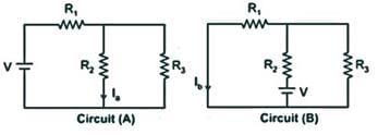
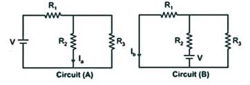
In circuit (a), the value Ia is obtained for a voltage source V. According to the reciprocity theorem, this current is equivalent to Ib in circuit B.
Limitations of reciprocity theorem:
In circuit (a), the value Ia is obtained for a voltage source V. According to the reciprocity theorem, this current is equivalent to Ib in circuit B.
Limitations of reciprocity theorem:
- The network should be bilateral linear and time-invariant.
- It can apply only to the single-source network and not for multi-source.
- It is also applicable for passive networks consisting L,C.
- Not applicable for circuits containing dependent sources even if it is linear.
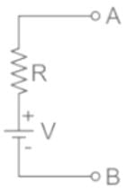
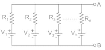
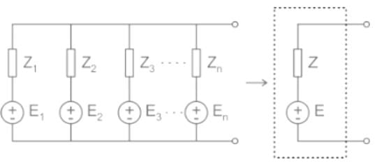
Name the theorem which states that if several ideal voltage sources in series are connected with impedance in parallel, then the circuit may be replaced with a single ideal source in series with an impedance (represented in the figure below).
- a)Norton's theorem
- b)Millman's theorem
- c)Tellegen's theorem
- d)Superposition theorem
Correct answer is option 'B'. Can you explain this answer?
Name the theorem which states that if several ideal voltage sources in series are connected with impedance in parallel, then the circuit may be replaced with a single ideal source in series with an impedance (represented in the figure below).
a)
Norton's theorem
b)
Millman's theorem
c)
Tellegen's theorem
d)
Superposition theorem
| | Pooja Patel answered |
Millman’s theorem:
- It is a very useful theorem to find out the voltage across the load and the current through the load.
- It is also called as parallel generator theorem.
- It is helpful to reduce a mixture of voltage and current sources connected in parallel to a single equivalent voltage or current source.
1. voltage source
It is stated that – when a number of voltage sources (V1, V2, V3……… Vn) are in parallel having internal resistance (R1, R2, R3………….Rn) respectively, the arrangement can replace by a single equivalent voltage source V in series with an equivalent series resistance R.
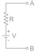
The equivalent circuit parameter
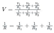
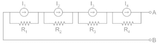
2. Current source:
It is state that – when a number of current sources (I1, I2, I3......In) are in series having internal resistance (R1, R2, R3………….Rn) respectively, the arrangement can replace by a single equivalent current source I in parallel with an equivalent series resistance R.
The equivalent circuit parameter
I = I1 + I2 + I3 ....... In
R = R1 + R2 + R3 ...... Rn
The equivalent circuit parameter
I = I1 + I2 + I3 ....... In
R = R1 + R2 + R3 ...... Rn
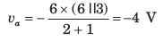
If vs1 = 6 V and vs 2 = -6 V then the value of vα is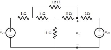
- a)4V
- b)-4V
- c)6V
- d)-6V
Correct answer is option 'B'. Can you explain this answer?
If vs1 = 6 V and vs 2 = -6 V then the value of vα is
a)
4V
b)
-4V
c)
6V
d)
-6V
| | Muskaan Nair answered |
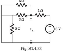
Since both source have opposite polarity, hence short circuit the all straight-through connection as shown in fig. S.1.4.33
If there are 3 10V sources connected in parallel then on source transformation__________- a)The effect of all the sources is considered
- b)The effect of only one source is considered
- c)The effect of none of the sources is considered
- d)The effect of only 2 sources is considered.
Correct answer is option 'B'. Can you explain this answer?
If there are 3 10V sources connected in parallel then on source transformation__________
a)
The effect of all the sources is considered
b)
The effect of only one source is considered
c)
The effect of none of the sources is considered
d)
The effect of only 2 sources is considered.
| | Kritika Gupta answered |
When voltages are connected in parallel, the effect of only one source is considered because the effect of the voltage remains the same when connected in parallel.
Find the voltage due to the 15A source.- a)0V
- b)2V
- c)4V
- d)6V
Correct answer is option 'A'. Can you explain this answer?
Find the voltage due to the 15A source.
a)
0V
b)
2V
c)
4V
d)
6V
| | Gargi Basak answered |
Due to the 15V source, the 10V and 16V sources get shorted and the 3A source acts as an open circuit. Since the 10V source is shorted, it acts as a low resistance path and current flows only within that loop and do not flow to the 20 ohm resistor. Hence the voltage is 0V.
The Norton current is the_______- a)Short circuit current
- b)Open circuit current
- c)Both open circuit and short circuit current
- d)Neither open circuit nor short circuit current
Correct answer is option 'A'. Can you explain this answer?
The Norton current is the_______
a)
Short circuit current
b)
Open circuit current
c)
Both open circuit and short circuit current
d)
Neither open circuit nor short circuit current
| | Uday Saini answered |
Norton current is the short circuit current. It is the current through the specified load resistance. It is not the open circuit current because open circuit current is equal to zero.
Norton’s theorem is true for __________- a)Linear networks
- b)Non-Linear networks
- c)Both linear networks and nonlinear networks
- d)Neither linear networks nor non-linear networks
Correct answer is option 'A'. Can you explain this answer?
Norton’s theorem is true for __________
a)
Linear networks
b)
Non-Linear networks
c)
Both linear networks and nonlinear networks
d)
Neither linear networks nor non-linear networks
| | Avantika Kaur answered |
Norton’s theorem works for only linear circuit elements and not non-linear ones such as BJT, semiconductors etc.
The Thevenin voltage is the__________- a)Open circuit voltage
- b)Short circuit voltage
- c)Both open circuit and short circuit voltage
- d)Neither open circuit nor short circuit voltage
Correct answer is option 'A'. Can you explain this answer?
The Thevenin voltage is the__________
a)
Open circuit voltage
b)
Short circuit voltage
c)
Both open circuit and short circuit voltage
d)
Neither open circuit nor short circuit voltage
| | Arshiya Basu answered |
Thevenin voltage is the open circuit voltage. It is the voltage across the specified terminals. It is not the short circuit voltage because short circuit voltage is equal to zero.
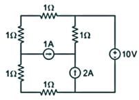
In the circuit shown below, the power supplied by the voltage source is?
- a)0 W
- b)5 W
- c)10 W
- d)100 W
Correct answer is option 'A'. Can you explain this answer?
In the circuit shown below, the power supplied by the voltage source is?
a)
0 W
b)
5 W
c)
10 W
d)
100 W
| | Pioneer Academy answered |
The circuit can be redrawn as:
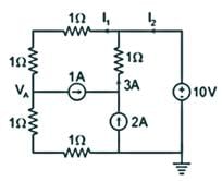
Applying KCL at node VA, we get:
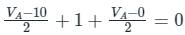
VA = 4
Now,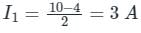
With I2 + 3 = I1
I2 + 3 = 3
I2 = 0 A
∴ Power delivered by the source = 10 x I2 = 0W
Applying KCL at node VA, we get:
VA = 4
Now,
With I2 + 3 = I1
I2 + 3 = 3
I2 = 0 A
∴ Power delivered by the source = 10 x I2 = 0W
In any bilateral network, if a source of EMF 'E' in any branch produces a current 'I' in any other branch, then the same EMF acting in the second branch would produce the same current 'I' in the first branch. This statement is associated with- a)Compensation theorem
- b)Superposition theorem
- c)Reciprocity theorem
- d)None of the above
Correct answer is option 'C'. Can you explain this answer?
In any bilateral network, if a source of EMF 'E' in any branch produces a current 'I' in any other branch, then the same EMF acting in the second branch would produce the same current 'I' in the first branch. This statement is associated with
a)
Compensation theorem
b)
Superposition theorem
c)
Reciprocity theorem
d)
None of the above
| | Yash Patel answered |
Reciprocity Theorem:
Reciprocity theorem states that in any branch of a network, the current (I) due to a single source of voltage (V) elsewhere in the network is equal to the current through the branch in which the source was originally placed when the source is placed in the branch in which the current (I) was originally obtained.
The ratio of excitation to the response is constant.
E/R = K
Where,
E is excitation
R is response
K is constant
It is applicable for only single-source networks.
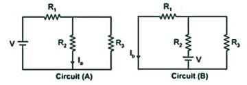
In-circuit (A), the value Ia is obtained for a voltage source V. According to the reciprocity theorem, this current is equivalent to Ib in a circuit (B).
Reciprocity theorem states that in any branch of a network, the current (I) due to a single source of voltage (V) elsewhere in the network is equal to the current through the branch in which the source was originally placed when the source is placed in the branch in which the current (I) was originally obtained.
The ratio of excitation to the response is constant.
E/R = K
Where,
E is excitation
R is response
K is constant
It is applicable for only single-source networks.
In-circuit (A), the value Ia is obtained for a voltage source V. According to the reciprocity theorem, this current is equivalent to Ib in a circuit (B).
Which of the following theorem states that the current at one point in a circuit due to a voltage at a second point is the same as the current at the second point due to the same voltage at the first?- a)Compensation Theorem
- b)Reciprocity Theorem
- c)Milliman's Theorem
- d)Superposition Theorem
Correct answer is option 'B'. Can you explain this answer?
Which of the following theorem states that the current at one point in a circuit due to a voltage at a second point is the same as the current at the second point due to the same voltage at the first?
a)
Compensation Theorem
b)
Reciprocity Theorem
c)
Milliman's Theorem
d)
Superposition Theorem
 | Machine Experts answered |
Reciprocity theorem:
Reciprocity theorem states that in any branch of a network, the current (I) due to a single source of voltage (V) elsewhere in the network is equal to the current through the branch in which the source was originally placed when the source is placed in the branch in which the current (I) was originally obtained.
Reciprocity theorem states that in any branch of a network, the current (I) due to a single source of voltage (V) elsewhere in the network is equal to the current through the branch in which the source was originally placed when the source is placed in the branch in which the current (I) was originally obtained.
In the circuit (a), the value Ia is obtained for a voltage source V. According to reciprocity theorem, this current is equivalent to Ib in the circuit B.
Limitations of reciprocity theorem:
- The network should be bilateral linear and time-invariant.
- It can apply only to the single-source network and not for multi-source.
- It is also applicable for passive networks consisting L,C.
- Not applicable for circuits containing dependent sources even if it is linear.
Which one of the following theorems is a manifestation of the Law of Conservation of Energy?- a)Tellegen's Theorem
- b)Reciprocity Theorem
- c)Thevenin's Theorem
- d)Norton's Theorem
Correct answer is option 'A'. Can you explain this answer?
Which one of the following theorems is a manifestation of the Law of Conservation of Energy?
a)
Tellegen's Theorem
b)
Reciprocity Theorem
c)
Thevenin's Theorem
d)
Norton's Theorem
| | Pooja Patel answered |
Different theorems used in the electrical network:
1.Tellegen's Theorem
It states that the power consumed by all the passive elements is always equal to the power delivered by all active elements.
Hence, this theorem is a manifestation of the Law of Conservation of Energy.
It states that the power consumed by all the passive elements is always equal to the power delivered by all active elements.
Hence, this theorem is a manifestation of the Law of Conservation of Energy.
2. Reciprocity Theorem:
It states that if the source and response of an electrical network are interchanged, then the parameters of the circuit remain the same.
It states that if the source and response of an electrical network are interchanged, then the parameters of the circuit remain the same.
3. Thevenin's Theorem:
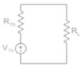
It states that any linear circuit containing several sources and resistances can be replaced by just one single voltagesource in series with a single resistance connected across the load.
It states that any linear circuit containing several sources and resistances can be replaced by just one single voltagesource in series with a single resistance connected across the load.
4. Norton's Theorem:
It states that any linear circuit containing several sources and resistances can be replaced by just one single current source in paralledwith a single resistance connected across the load.
It states that any linear circuit containing several sources and resistances can be replaced by just one single current source in paralledwith a single resistance connected across the load.


Does maximum power transfer imply maximum efficiency?- a)Yes
- b)No
- c)Sometimes
- d)Cannot be determined
Correct answer is option 'B'. Can you explain this answer?
Does maximum power transfer imply maximum efficiency?
a)
Yes
b)
No
c)
Sometimes
d)
Cannot be determined
| | Om Saini answered |
Maximum power transfer does not imply maximum efficiency. If the load resistance is smaller than source resistance, power dissipated at the load is reduced while most of the power is dissipated at the source then the efficiency becomes lower.
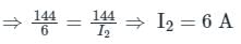
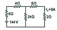 If I1 in the given circuit is 6 A, what will be the current I2 in the following circuit?
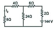
- a)6 A
- b)3 A
- c)-3 A
- d)< 3 A
Correct answer is option 'A'. Can you explain this answer?
If I1 in the given circuit is 6 A, what will be the current I2 in the following circuit?
a)
6 A
b)
3 A
c)
-3 A
d)
< 3 A
 | Gate Gurus answered |
Reciprocity Theorem:
In any passive linear bilateral network, if a single voltage source ‘V’ in the branch AB produces the current response ‘I’ in the branch CD, then the removal of voltage source from the branch AB and its insertion in the branch CD will produce same current ‘I’ in the branch AB.
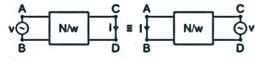
In reciprocity theorem, if the position of excitation and responses are interchanged, then their ratio remains the same.

Circuit 1: V1 = 144 V, I1 = 6 A
Circuit 2: V2 = 144 V, I2 = ?
According to reciprocity theorem,

In any passive linear bilateral network, if a single voltage source ‘V’ in the branch AB produces the current response ‘I’ in the branch CD, then the removal of voltage source from the branch AB and its insertion in the branch CD will produce same current ‘I’ in the branch AB.
In reciprocity theorem, if the position of excitation and responses are interchanged, then their ratio remains the same.
Circuit 1: V1 = 144 V, I1 = 6 A
Circuit 2: V2 = 144 V, I2 = ?
According to reciprocity theorem,
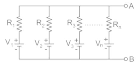
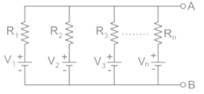
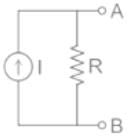
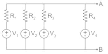
Which of the following helps in finding a single equivalent voltage source of the circuit shown in the figure?
- a)Thevenin’s theorem
- b)Norton’s theorem
- c)Millman’s theorem
- d)Reciprocity theorem
Correct answer is option 'C'. Can you explain this answer?
Which of the following helps in finding a single equivalent voltage source of the circuit shown in the figure?
a)
Thevenin’s theorem
b)
Norton’s theorem
c)
Millman’s theorem
d)
Reciprocity theorem
| | Pooja Patel answered |
Millman’s Theorem:
(1) voltage source: It is states that – when a number of voltage sources (V1, V2, V3……… Vn) are in parallel having internal resistance (R1, R2, R3………….Rn) respectively, the arrangement can replace by a single equivalent voltage source V in series with an equivalent series resistance R.


The equivalent circuit parameter

(2) Current source: It is state that – when a number of current sources (I1, I2, I3......In) are in series having internal resistance (R1, R2, R3………….Rn) respectively, the arrangement can replace by a single equivalent current source I in parallel with an equivalent series resistance R.


The equivalent circuit parameter

R = R1 + R2 + R3 ...... Rn
(1) voltage source: It is states that – when a number of voltage sources (V1, V2, V3……… Vn) are in parallel having internal resistance (R1, R2, R3………….Rn) respectively, the arrangement can replace by a single equivalent voltage source V in series with an equivalent series resistance R.
The equivalent circuit parameter
(2) Current source: It is state that – when a number of current sources (I1, I2, I3......In) are in series having internal resistance (R1, R2, R3………….Rn) respectively, the arrangement can replace by a single equivalent current source I in parallel with an equivalent series resistance R.
The equivalent circuit parameter
R = R1 + R2 + R3 ...... Rn
Which of the following step for solution of a network utilizing reciprocity theorem is truly stated?- a)The current in the branch where voltage source was existing earlier is calculated
- b)The current source is interchanged between the branches concerned
- c)The voltage in the branch is obtained using conventional network analysis
- d)The branch between reciprocity is to be established after computing voltage
Correct answer is option 'A'. Can you explain this answer?
Which of the following step for solution of a network utilizing reciprocity theorem is truly stated?
a)
The current in the branch where voltage source was existing earlier is calculated
b)
The current source is interchanged between the branches concerned
c)
The voltage in the branch is obtained using conventional network analysis
d)
The branch between reciprocity is to be established after computing voltage
| | Pooja Patel answered |
Reciprocity Theorem:
- The reciprocity theorem states that the current at one point in a circuit due to a voltage at a second point is the same as the current at the second point due to the same voltage at the first.
- The reciprocity theorem is valid for all passive networks.
If source impedance is a complex number Z, then load impedance is equal to _________- a)Z’
- b)-Z
- c)-Z’
- d)Z
Correct answer is option 'A'. Can you explain this answer?
If source impedance is a complex number Z, then load impedance is equal to _________
a)
Z’
b)
-Z
c)
-Z’
d)
Z
| | Raj Singh answered |
When Source impedance is equal to Z, its load impedance is the complex conjugate of Z which is Z’. Only under this condition maximum power can be drawn from the circuit.
The maximum power drawn from source depends on__________- a)Value of source resistance
- b)Value of load resistance
- c)Both source and load resistance
- d)Neither source or load resistance
Correct answer is option 'B'. Can you explain this answer?
The maximum power drawn from source depends on__________
a)
Value of source resistance
b)
Value of load resistance
c)
Both source and load resistance
d)
Neither source or load resistance
| | Divya Nair answered |
The maximum power transferred is equal to:
I2RL, when load resistance is variable.
Es2/4RL, when load impedance is variable.
In both the cases, the maximum power depends on the load resistance.
I2RL, when load resistance is variable.
Es2/4RL, when load impedance is variable.
In both the cases, the maximum power depends on the load resistance.
Can we use Norton’s theorem on a circuit containing a BJT?- a)Yes
- b)No
- c)Depends on the BJT
- d)Insufficient data provided
Correct answer is option 'B'. Can you explain this answer?
Can we use Norton’s theorem on a circuit containing a BJT?
a)
Yes
b)
No
c)
Depends on the BJT
d)
Insufficient data provided
| | Srestha Gupta answered |
We can use Norton’s theorem only for linear networks. BJT is a non-linear network hence we cannot apply Norton’s theorem for it.
Chapter doubts & questions for Network Theorems - 6 Months Preparation for GATE Electrical 2026 is part of Electrical Engineering (EE) exam preparation. The chapters have been prepared according to the Electrical Engineering (EE) exam syllabus. The Chapter doubts & questions, notes, tests & MCQs are made for Electrical Engineering (EE) 2026 Exam. Find important definitions, questions, notes, meanings, examples, exercises, MCQs and online tests here.
Chapter doubts & questions of Network Theorems - 6 Months Preparation for GATE Electrical in English & Hindi are available as part of Electrical Engineering (EE) exam. Download more important topics, notes, lectures and mock test series for Electrical Engineering (EE) Exam by signing up for free.
6 Months Preparation for GATE Electrical675 videos|1390 docs|885 tests |