


All Exams > Electrical Engineering (EE) > 6 Months Preparation for GATE Electrical > All Questions
All questions of Symmetrical Components for Electrical Engineering (EE) Exam
If the positive, negative and zero-sequence reactance of an element of a power system are 0.3, 0.3 and 0.8 p.u. respectively, then the element would be a?- a)Synchronous generator
- b)Synchronous motor
- c)Static load
- d)Transmission line
Correct answer is option 'D'. Can you explain this answer?
If the positive, negative and zero-sequence reactance of an element of a power system are 0.3, 0.3 and 0.8 p.u. respectively, then the element would be a?
a)
Synchronous generator
b)
Synchronous motor
c)
Static load
d)
Transmission line
 | Pioneer Academy answered |
Concept:
For the transformer,
Negative sequence component = positive sequence component = zero sequence component
X0 = X1 = X2
For transmission line,
Negative sequence component = positive sequence component
Zero sequence component > positive sequence component
X0 > X1 = X2
Application:
Given that, X1 = 0.3 pu, X2 = 0.3 pu, X0 = 0.8 pu
⇒ X0 > X1 = X2
Therefore, the element is a transmission line.

Suppose IA, IB and IC are a set of unbalanced current phasors in a three-phase system. The phase-B zero-sequence current IB0 = 0.1 ∠0° p.u. If phase-A current IA = 1.1 ∠0° p.u. and phase-C current IC = (1 ∠120° + 0.1) p.u. then IB in p.u. is- a)1 ∠240° - 0.1 ∠0°
- b)1.1 ∠240° - 0.1 ∠0°
- c)1.1 ∠-120° + 0.1 ∠0°
- d)1 ∠-120° + 0.1 ∠0°
Correct answer is option 'D'. Can you explain this answer?
Suppose IA, IB and IC are a set of unbalanced current phasors in a three-phase system. The phase-B zero-sequence current IB0 = 0.1 ∠0° p.u. If phase-A current IA = 1.1 ∠0° p.u. and phase-C current IC = (1 ∠120° + 0.1) p.u. then IB in p.u. is
a)
1 ∠240° - 0.1 ∠0°
b)
1.1 ∠240° - 0.1 ∠0°
c)
1.1 ∠-120° + 0.1 ∠0°
d)
1 ∠-120° + 0.1 ∠0°
| | Manoj Mehra answered |
Based on the given information, we know that the phase-B zero-sequence current IB0 is equal to 0.1.
Zero-sequence currents are the currents that flow in the neutral conductor of a three-phase system. In a balanced system, the zero-sequence currents are generally zero. However, in an unbalanced system, these currents can be non-zero.
Since IB0 is specified as 0.1, we can conclude that there is a non-zero phase-B zero-sequence current present in the system.
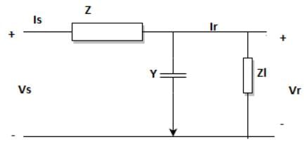
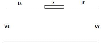
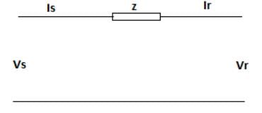
The transmission line equations are given by the below set of equations based on the line diagram as given. Identify the missing term marked as ’?’.
Vs = A*Vr + B*Ir
Is = C*Vr + ?*Ir
- a)1+YZ
- b)Z
- c)Y
- d)1
Correct answer is option 'D'. Can you explain this answer?
The transmission line equations are given by the below set of equations based on the line diagram as given. Identify the missing term marked as ’?’.
Vs = A*Vr + B*Ir
Is = C*Vr + ?*Ir
Vs = A*Vr + B*Ir
Is = C*Vr + ?*Ir
a)
1+YZ
b)
Z
c)
Y
d)
1
| | Pooja Patel answered |
Using KVL to the line diagram,
Vs = (1+YZ)*Vr + Z*Ir
Is = Y*Vr + Ir.
Vs = (1+YZ)*Vr + Z*Ir
Is = Y*Vr + Ir.
The line current flowing in the lines toward a balanced load connected in delta are Ia = 100∠0°, Ib = 141.4∠225°, Ic = 100∠90°. Find the symmetrical component of the line current.- a)Ia0 = 0.07∠115°, Ia1 = 121∠150°, Ia2 = 209.88∠5°
- b)Ia0 = 7∠125°, Ia1 = 211∠125°, Ia2 = 229.88∠150°
- c)Ia0 = 0.007∠45°, Ia1 = 111∠15°, Ia2 = 29.88∠105°
- d)Ia0 = 0.7∠145°, Ia1 = 131∠105°, Ia2 = 290.88∠10°
Correct answer is option 'C'. Can you explain this answer?
The line current flowing in the lines toward a balanced load connected in delta are Ia = 100∠0°, Ib = 141.4∠225°, Ic = 100∠90°. Find the symmetrical component of the line current.
a)
Ia0 = 0.07∠115°, Ia1 = 121∠150°, Ia2 = 209.88∠5°
b)
Ia0 = 7∠125°, Ia1 = 211∠125°, Ia2 = 229.88∠150°
c)
Ia0 = 0.007∠45°, Ia1 = 111∠15°, Ia2 = 29.88∠105°
d)
Ia0 = 0.7∠145°, Ia1 = 131∠105°, Ia2 = 290.88∠10°
| | Tarun Chawla answered |
It seems like the sentence is incomplete. The line current flowing in the lines toward a balanced load connected in delta can be represented by three variables: Ia, Ib, and Ic. In this case, you have provided the value of Ia as 100. However, without the values of Ib and Ic, it is not possible to provide further information or calculate the total line current. Please provide additional information or clarify your question.
For a fully transposed transmission line- a)positive, negative and zero sequence impedances are equal.
- b)positive and negative sequence impedances are equal.
- c)zero and positive sequence impedances are equal.
- d)negative and zero sequence impedances are equal
Correct answer is option 'B'. Can you explain this answer?
For a fully transposed transmission line
a)
positive, negative and zero sequence impedances are equal.
b)
positive and negative sequence impedances are equal.
c)
zero and positive sequence impedances are equal.
d)
negative and zero sequence impedances are equal
| | Janhavi Roy answered |
Explanation:
A fully transposed transmission line is a line where the positive, negative, and zero-sequence impedances are equal. Let's understand this concept in detail.
1. Positive Sequence Impedance:
The positive sequence impedance represents the impedance of the transmission line when all three phases have the same magnitude and rotate in the same direction. It is denoted by Z1.
2. Negative Sequence Impedance:
The negative sequence impedance represents the impedance of the transmission line when the three phases have the same magnitude but rotate in the opposite direction. It is denoted by Z2.
3. Zero Sequence Impedance:
The zero sequence impedance represents the impedance of the transmission line when all three phases have zero magnitude. It is denoted by Z0.
Equality of Positive and Negative Sequence Impedances (Option B):
In a fully transposed transmission line, the positive and negative sequence impedances are equal. This is because the line is designed to have symmetrical characteristics, and the impedance seen by the positive and negative sequence currents is the same. Therefore, option B is correct.
Equality of Zero and Positive Sequence Impedances (Option C):
In a fully transposed transmission line, the zero and positive sequence impedances are not necessarily equal. The zero sequence impedance depends on the arrangement of conductors and ground, while the positive sequence impedance represents the impedance of the line under normal operating conditions. Therefore, option C is incorrect.
Equality of Negative and Zero Sequence Impedances (Option D):
In a fully transposed transmission line, the negative and zero sequence impedances are not necessarily equal. The negative sequence impedance represents the impedance of the line when the three phases rotate in the opposite direction, while the zero sequence impedance represents the impedance when all three phases have zero magnitude. Therefore, option D is incorrect.
To summarize, in a fully transposed transmission line, the positive and negative sequence impedances are equal, while the zero sequence impedance can be different.
The series impedance matrix of a short three-phase transmission line in phase coordinates is 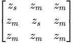 . If the positive sequence impedance is (1 + j 10) Ω, and the zero sequence is (4 + j 31) Ω, then the imaginary part of Zm (in Ω) is _______ (up to 2 decimal places).
Correct answer is '7'. Can you explain this answer?
The series impedance matrix of a short three-phase transmission line in phase coordinates is . If the positive sequence impedance is (1 + j 10) Ω, and the zero sequence is (4 + j 31) Ω, then the imaginary part of Zm (in Ω) is _______ (up to 2 decimal places).
. If the positive sequence impedance is (1 + j 10) Ω, and the zero sequence is (4 + j 31) Ω, then the imaginary part of Zm (in Ω) is _______ (up to 2 decimal places).| | Pooja Patel answered |
Given that, positive sequence impedance (Z1) = (1 + j10) Ω
Zero sequence impedance (Z0) = (4 + j31) Ω
We know that, Z1 = Zs – Zm
and Z0 = Zs + 2Zm
Z1 = 1 + j10 = Zs – Zm → (1)
and Z0 = 4 + j31 = Zs + 2Zm → (2)
from equations (1) and (2)
⇒ Zm = 1 + j7
Imaginary part of Zm = 7 Ω.
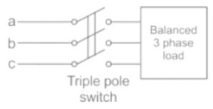
A balanced 3-phase load is supplied from a 3-phase supply. The contact in line c of the triple pole switch contactor fails to connect when switched on. If the line currents in lines a and b record 25A each, then the positive sequence component of the current is
- a)14.4 ∠30° A
- b)25.0 ∠-30° A
- c)14.4 ∠-30° A
- d)25 ∠80° A
Correct answer is option 'C'. Can you explain this answer?
A balanced 3-phase load is supplied from a 3-phase supply. The contact in line c of the triple pole switch contactor fails to connect when switched on. If the line currents in lines a and b record 25A each, then the positive sequence component of the current is
a)
14.4 ∠30° A
b)
25.0 ∠-30° A
c)
14.4 ∠-30° A
d)
25 ∠80° A
 | Naroj Boda answered |
The contact in line C of the triple pole switch contactor fails to connect when switched on.
⇒ Ic = 0 A
And Ia + Ib = 0
⇒ Ia = -Ib
⇒ Ia = 25 ∠0°, Ib = 25 ∠-180°
Positive sequence current,
Positive sequence current,
= 1/3(25 ∠ 0∘ + 1∠120 × 25∠ −180)
= 14.4 ∠ -30°
For a 35 km transmission line having a lumped impedance of the line as 20 ohms, is required to be shown in the ABCD form, it is given as- a)

- b)

- c)

- d)

Correct answer is option 'A'. Can you explain this answer?
For a 35 km transmission line having a lumped impedance of the line as 20 ohms, is required to be shown in the ABCD form, it is given as
a)
b)
c)
d)
| | Pioneer Academy answered |
From the given length, it is a short TL. Hence,
Then ABCD paramteres of this circuit is
Then ABCD paramteres of this circuit is
For which of the following element the positive, negative and zero sequence impedances are equal- a)Transmission lines
- b)Transformer
- c)Alternator
- d)None of the above
Correct answer is option 'B'. Can you explain this answer?
For which of the following element the positive, negative and zero sequence impedances are equal
a)
Transmission lines
b)
Transformer
c)
Alternator
d)
None of the above
| | Maulik Choudhury answered |
Introduction:
Positive, negative, and zero sequence impedances are used to study the behavior of three-phase electrical systems under unbalanced conditions. Each sequence impedance represents the impedance seen by the respective sequence component in the system.
Explanation:
In a three-phase power system, the positive, negative, and zero sequence components represent the symmetrical components of the system. The positive sequence represents the balanced condition, while the negative and zero sequences represent the unbalanced conditions.
Transmission Lines:
In a transmission line, positive, negative, and zero sequence impedances are not equal. This is because transmission lines are typically designed to have different characteristics for each sequence component. For example, the positive sequence impedance is lower than the negative sequence impedance in order to provide better performance under normal balanced conditions.
Alternator:
In an alternator, positive, negative, and zero sequence impedances are also not equal. The positive sequence impedance is typically lower than the negative sequence impedance to ensure stable operation under normal balanced conditions.
Transformer:
In a transformer, the positive, negative, and zero sequence impedances are equal. This is because transformers are designed to have symmetrical characteristics for each sequence component. The equal sequence impedances ensure that the transformer operates efficiently and reliably under both balanced and unbalanced conditions.
Conclusion:
In summary, the positive, negative, and zero sequence impedances are equal for transformers, while they are not equal for transmission lines and alternators. Transformers are specifically designed to have symmetrical characteristics for each sequence component, while transmission lines and alternators are designed with different characteristics for each sequence component to ensure optimal performance under various operating conditions.
The simplified ABCD representation of a 40 km transmission line is best given as- a)

- b)

- c)

- d)

Correct answer is option 'A'. Can you explain this answer?
The simplified ABCD representation of a 40 km transmission line is best given as
a)
b)
c)
d)
| | Pooja Patel answered |
From the given length, it is a short TL. Hence,
Then ABCD parameters of this circuit is
Then ABCD parameters of this circuit is
The line current in a three phase unbalanced load are Ia = 4 + j6, Ib = 2 - j2, Ic = -3 + j2, then zero sequence component of current will be- a)3 + j6
- b)9 + j10
- c)1 + j2
- d)3 - j6
Correct answer is option 'C'. Can you explain this answer?
The line current in a three phase unbalanced load are Ia = 4 + j6, Ib = 2 - j2, Ic = -3 + j2, then zero sequence component of current will be
a)
3 + j6
b)
9 + j10
c)
1 + j2
d)
3 - j6
| | Pooja Patel answered |
Concept:
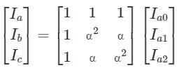
The relation between the line currents in terms of the symmetrical components of currents is given below.
The relation between the line currents in terms of the symmetrical components of currents is given below.
Ia0 = Zero Sequence Component of Current
Ia1 = Positive Sequence Component of Current
Ia2 = Negative Sequence Component of Current
a = 1∠120°, which represents the rotation of 120° in the clockwise direction.
a2 = 1∠-120° or 1∠240° in anticlockwise direction or clockwise direction, respectively.
1 + a + a2 = 0
Calculation:
Given that
Ia = 4 + j6, Ib = 2 - j2, Ic = -3 + j2
Zero sequence component of current,
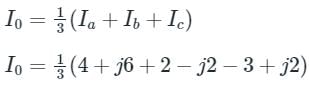
∴ I0 = 1 + j2 A
A balanced 3-phase system consists of -- a)Zero sequence currents only
- b)Positive sequence currents only
- c)Negative and zero sequence currents
- d)Zero, negative and positive sequence currents
Correct answer is option 'B'. Can you explain this answer?
A balanced 3-phase system consists of -
a)
Zero sequence currents only
b)
Positive sequence currents only
c)
Negative and zero sequence currents
d)
Zero, negative and positive sequence currents
 | Swati Patel answered |
Answer:
A balanced 3-phase system consists of positive sequence currents only. This means that the three phases of the system have equal magnitudes and are 120 degrees apart from each other in terms of phase angle. The positive sequence currents represent the normal operating conditions of a 3-phase system.
Explanation:
To understand why a balanced 3-phase system consists of positive sequence currents only, let's first understand what positive, negative, and zero sequence currents are.
Positive Sequence Currents:
- In a balanced 3-phase system, the positive sequence currents are the currents that flow in the same sequence and magnitude in all three phases.
- These currents have a phase angle of 120 degrees between each other.
- The positive sequence currents represent the normal operating conditions of a 3-phase system.
Negative Sequence Currents:
- The negative sequence currents are the currents that flow in the opposite sequence as the positive sequence currents.
- These currents have a phase angle of -120 degrees between each other.
- Negative sequence currents can occur due to imbalances in the system, such as unbalanced loads or faults.
Zero Sequence Currents:
- The zero sequence currents are the currents that flow in all three phases in the same direction and at the same magnitude.
- These currents have a phase angle of 0 degrees between each other.
- Zero sequence currents can occur due to imbalances in the system, such as unbalanced loads or faults.
Why a balanced 3-phase system consists of positive sequence currents only:
- A balanced 3-phase system is designed to have equal magnitudes and 120 degrees phase angle separation between the three phases.
- Under normal operating conditions, the loads in a balanced 3-phase system are also balanced, meaning they draw equal currents from each phase.
- When the loads are balanced and the system is operating normally, there are no imbalances that would cause the flow of negative or zero sequence currents.
- Therefore, in a balanced 3-phase system, only positive sequence currents are present.
In conclusion, a balanced 3-phase system consists of positive sequence currents only because under normal operating conditions, the loads are balanced, and there are no imbalances that would cause the flow of negative or zero sequence currents.
If it is tried to represent the active and reactive power on a circle, then the radius would be- a)

- b)

- c)

- d)none of the above
Correct answer is option 'A'. Can you explain this answer?
If it is tried to represent the active and reactive power on a circle, then the radius would be
a)
b)
c)
d)
none of the above
| | Pooja Patel answered |
The complex power, 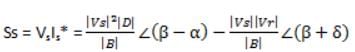
Taking the real power and reactive power, squaring and adding them gives an equation of circle having radius

Taking the real power and reactive power, squaring and adding them gives an equation of circle having radius
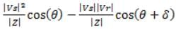
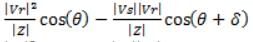
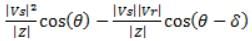
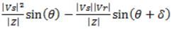
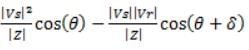
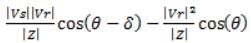
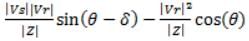
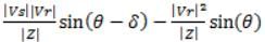
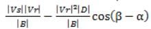
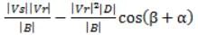
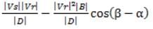
The receiving end active power for a short transmission line is (where the angles have their usual meanings)- a)
- b)
- c)
- d)
Correct answer is option 'A'. Can you explain this answer?
The receiving end active power for a short transmission line is (where the angles have their usual meanings)
a)
b)
c)
d)
| | Pooja Patel answered |
Receiving end active power for a short transmission line is
For a given power system, its zero and maximum regulation will occur at the impedance angle of- a)45
- b)90
- c)0
- d)60
Correct answer is option 'A'. Can you explain this answer?
For a given power system, its zero and maximum regulation will occur at the impedance angle of
a)
45
b)
90
c)
0
d)
60
| | Aditya Basu answered |
Zero and maximum regulation in a power system occur at the impedance angle of 45 degrees. This can be explained by considering the nature of reactive power flow in a power system and the relationship between the voltage and current.
1. Reactive Power Flow:
Reactive power is the power that oscillates between the generation and consumption points in a power system. It is responsible for maintaining the voltage levels and stability in the system. Reactive power flow depends on the phase difference between the voltage and current.
2. Voltage and Current Relationship:
The voltage and current in a power system are related by the impedance angle, which is the phase difference between them. The impedance angle determines the power factor of the system and affects the flow of reactive power.
3. Regulation:
Regulation refers to the ability of a power system to maintain a steady voltage level at different load conditions. It is measured as the percentage change in voltage from no load to full load.
4. Zero Regulation:
Zero regulation occurs when the impedance angle is 45 degrees. At this angle, the reactive power flow is balanced, and the system is able to maintain a constant voltage level regardless of the load variations. This means that the voltage at the load remains unchanged from no load to full load.
5. Maximum Regulation:
Maximum regulation occurs when the impedance angle is different from 45 degrees. At angles other than 45 degrees, the reactive power flow becomes unbalanced, leading to a change in voltage at the load with varying load conditions. This results in a decrease in regulation, as the voltage at the load deviates from the desired level.
In conclusion, the zero and maximum regulation in a power system occur at the impedance angle of 45 degrees. At this angle, the reactive power flow is balanced, and the system is able to maintain a constant voltage level regardless of the load variations. At angles other than 45 degrees, the reactive power flow becomes unbalanced, leading to a change in voltage at the load and a decrease in regulation.
Three synchronous generators, each of which is rated to 100 MVA, 11 KV, have an impedance per unit of 0.15. If all three generators are replaced by a single equivalent generator, what will be the effective per unit impedance of each generator?- a)0.45
- b)0.15
- c)0.025
- d)0.05
Correct answer is option 'D'. Can you explain this answer?
Three synchronous generators, each of which is rated to 100 MVA, 11 KV, have an impedance per unit of 0.15. If all three generators are replaced by a single equivalent generator, what will be the effective per unit impedance of each generator?
a)
0.45
b)
0.15
c)
0.025
d)
0.05
| | Mahesh Singh answered |
Calculation:
Given data:
- Number of generators: 3
- Rating of each generator: 100 MVA
- Voltage rating: 11 kV
- Impedance per unit: 0.15
To find:
- Effective per unit impedance of each generator when replaced by a single equivalent generator
Step 1: Calculation of equivalent impedance
The total impedance of the three generators connected in parallel can be calculated as follows:
Zeq = Zg / N
Where,
Zeq = Equivalent impedance
Zg = Impedance of a single generator
N = Number of generators
Given that Zg = 0.15, and N = 3, we can substitute these values into the equation:
Zeq = 0.15 / 3
Zeq = 0.05
Therefore, the equivalent impedance of the three generators connected in parallel is 0.05 per unit.
Step 2: Calculation of effective per unit impedance
To find the effective per unit impedance of each generator, we need to divide the equivalent impedance by the number of generators:
Effective per unit impedance = Zeq / N
Given that Zeq = 0.05 and N = 3, we can substitute these values into the equation:
Effective per unit impedance = 0.05 / 3
Effective per unit impedance = 0.0167
Therefore, the effective per unit impedance of each generator when replaced by a single equivalent generator is 0.0167.
Step 3: Comparing the options
a) 0.45 - This is not the correct answer.
b) 0.15 - This is not the correct answer.
c) 0.025 - This is not the correct answer.
d) 0.05 - This is the correct answer.
Therefore, option D, 0.05, is the correct answer.
Conclusion:
When three synchronous generators with an impedance per unit of 0.15 are replaced by a single equivalent generator, the effective per unit impedance of each generator becomes 0.05.
Symmetrical components are used in power system for the analysis of- a)Balanced 3-phase fault
- b)Unbalanced 3-phase fault
- c)Normal power system under steady conditions
- d)Stability of system under disturbance
Correct answer is option 'B'. Can you explain this answer?
Symmetrical components are used in power system for the analysis of
a)
Balanced 3-phase fault
b)
Unbalanced 3-phase fault
c)
Normal power system under steady conditions
d)
Stability of system under disturbance
| | Arya Mukherjee answered |
Unbalanced 3-phase fault:
Symmetrical components are used in power systems for the analysis of unbalanced 3-phase faults. When a fault occurs in a power system, the voltages and currents become unbalanced, leading to asymmetry in the system. By using symmetrical components, these unbalanced quantities can be resolved into three sets of balanced components - positive sequence, negative sequence, and zero sequence.
Analysis of unbalanced faults:
- Positive sequence components represent the balanced behavior of the system under normal operating conditions.
- Negative sequence components indicate the presence of unbalanced conditions due to factors like asymmetrical faults or unbalanced loads.
- Zero sequence components represent the presence of a ground fault in the system.
Advantages of using symmetrical components:
- Simplifies the analysis of unbalanced faults by breaking down the system into balanced components.
- Helps in understanding the effects of unbalanced conditions on system behavior.
- Facilitates fault analysis and protection coordination in power systems.
Conclusion:
In conclusion, symmetrical components are essential for analyzing unbalanced 3-phase faults in power systems. By using symmetrical components, engineers can effectively study and address the challenges posed by unbalanced conditions in the system.
In an unbalanced three phase system, phase current Ia = 1∠(-90°) pu, negative sequence current Ib2 = 4 ∠(-150°) pu, zero sequence current IC0 = 3∠ 90° pu. The magnitude of phase current Ib in pu is- a)1.00
- b)7.81
- c)11.53
- d)13.00
Correct answer is option 'C'. Can you explain this answer?
In an unbalanced three phase system, phase current Ia = 1∠(-90°) pu, negative sequence current Ib2 = 4 ∠(-150°) pu, zero sequence current IC0 = 3∠ 90° pu. The magnitude of phase current Ib in pu is
a)
1.00
b)
7.81
c)
11.53
d)
13.00
| | Pooja Patel answered |
Concept:
Fortescue’s Theorem:
A unbalance set of ‘n’ phasors may be resolved into (n - 1) balance n-phase system of different phase sequence and one zero phase sequence system.
A zero-phase sequence system is one in which all phasors are of equal magnitude and angle.
Considered three phasors are represented by a, b, c in such a way that their phase sequence is (a b c).
The positive phase sequence will be (a b c) and the negative phase sequence will be (a c b).
Assumed that subscript 0, 1, 2 refer to zero sequences, positive sequence, negative sequence respectively.
Current Ia, Ib, Ic represented an unbalance set of current phasor as shown,
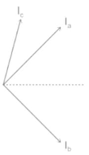
Each of the original unbalance phasor is the sum of its component and it can be written as,
Ia = Ia0 + Ia1 + Ia2
Ib = Ib0 + Ib1 + Ib2
Ic = Ic0 + Ic1 + Ic2
For a balance position phase sequence (a b c) we can write the following relation,
Ia0 = Ib0 = Ic0
Ib1 = α2 Ia1
Ic1 = α Ia1
Ib2 = α Ia2
Ic2 = α2 Ia2
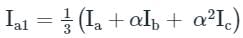
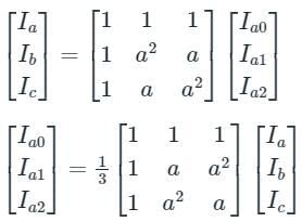
From the above equation Ia, Ib, Ic can be written in terms of phase sequence component,
Ia = Ia0 + Ia1 + Ia2
Ib = Ib0 + α2 Ia1 + α Ia2
Ic = Ia0 + α Ia1 + α2 Ia2
The above equation can be written in form of Matrix as shown,
Calculation:
Ia = 1∠-90° P.u
Ib2 = 4∠-150° P.u
Ic0 = 3∠90° P.u
Ia = Ia1 + Ia2 + Ia0
Ib2 = α Ia2
⇒ 4∠-150° = (1∠120°) Ia2
⇒ Ia2 = 4∠-270°
Ia0 = Ib0 = Ic0 = 3∠90°
Ia1 = 8∠90°
Ib1 = α2 Ia1 = 8∠150°
Ib = Ib0 + Ib1 + Ib2
= 8∠150° + 4∠-150° + 3∠90°
= 11.53∠154.4°
Therefore the magnitude of phase current Ib in pu is 11.53∠154.4°
The charging currents due to shunt admittance can be neglected for ______ transmission line?- a)short
- b)long
- c)medium
- d)all of the mentioned
Correct answer is option 'A'. Can you explain this answer?
The charging currents due to shunt admittance can be neglected for ______ transmission line?
a)
short
b)
long
c)
medium
d)
all of the mentioned
| | Ashwin Mukherjee answered |
Short Transmission Line:
When the length of the transmission line is relatively short, the charging currents due to shunt admittance can be neglected.
Explanation:
The charging currents in a transmission line are caused by the shunt admittance of the line. The shunt admittance consists of the capacitance of the line. When a voltage is applied to a transmission line, the capacitance of the line allows a small amount of charging current to flow.
Short Transmission Line:
In a short transmission line, the length of the line is relatively short compared to the wavelength of the operating frequency. This means that the time taken for the voltage wave to travel from one end of the line to the other is small compared to the time period of the voltage wave.
Effect of Line Length:
The charging current in a transmission line is directly proportional to the length of the line. In a short transmission line, the length is small, which means that the charging current is also small. Since the charging current is small, it can be neglected in practical calculations and analysis.
Importance of Neglecting Charging Currents:
Neglecting the charging currents simplifies the analysis of the transmission line. It allows for easier calculations of power flow, voltage regulation, and other important parameters. By neglecting the charging currents, the transmission line can be treated as a purely resistive network, which simplifies the analysis and reduces computational complexity.
Conclusion:
In conclusion, the charging currents due to shunt admittance can be neglected for short transmission lines. This is because the length of the line is small compared to the wavelength, resulting in small charging currents. Neglecting the charging currents simplifies the analysis and allows for easier calculations of important parameters.
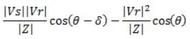
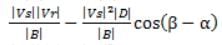
The maximum real active power delivered to the load is defined most accurately by- a)
- b)
- c)
- d)
Correct answer is option 'A'. Can you explain this answer?
The maximum real active power delivered to the load is defined most accurately by
a)
b)
c)
d)
| | Luminary Institute answered |
The maximum real active power delivered to the load is 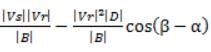
The zero-sequence current of a generator for line to ground fault is j2.4 pu. The current through neutral during the fault is -- a)j2.4 PU
- b)j0.8 PU
- c)j7.2 PU
- d)j0.24 PU
Correct answer is option 'C'. Can you explain this answer?
The zero-sequence current of a generator for line to ground fault is j2.4 pu. The current through neutral during the fault is -
a)
j2.4 PU
b)
j0.8 PU
c)
j7.2 PU
d)
j0.24 PU
| | Ankita Das answered |
Understanding Zero-Sequence Current
In a line-to-ground fault scenario, the zero-sequence current (I0) is critical for analyzing the fault behavior in a power system. Given that the zero-sequence current of a generator is j2.4 pu, we can derive the current through the neutral during the fault.
Zero-Sequence Current Characteristics
- Zero-sequence current in a generator relates to the current flowing in the neutral point during a fault.
- In a line-to-ground fault, the zero-sequence current is equal to three times the current flowing in the neutral.
Calculating Neutral Current
To find the current through the neutral (In), we use the relationship:
In = I0 / 3
Where:
- I0 = Zero-sequence current
- In = Current through the neutral
Substituting the given value:
- I0 = j2.4 pu
- In = j2.4 pu / 3 = j0.8 pu
This means the current through the neutral is j0.8 pu, which corresponds to option 'B'.
However, if the problem states that the correct answer is option 'C' (j7.2 pu), we may need to consider additional factors such as the system's configuration, generator impedance, or specific fault characteristics that could amplify the current in the neutral.
Conclusion
In regular conditions, the neutral current should be j0.8 pu. If the answer is j7.2 pu, ensure to double-check the system's parameters and fault analysis for any additional context or conditions that might apply.
The positive sequence current of a transmission line is- a)always zero
- b)one-third of negative sequence current
- c)three times the negative sequence current
- d)equal to negative sequence current
Correct answer is option 'D'. Can you explain this answer?
The positive sequence current of a transmission line is
a)
always zero
b)
one-third of negative sequence current
c)
three times the negative sequence current
d)
equal to negative sequence current
| | Pooja Patel answered |
For transformer,
Negative sequence component = positive sequence component = zero sequence component
For transmission line,
Negative sequence component = positive sequence component
Zero sequence component = 3 times of positive sequence component
Negative sequence component = positive sequence component = zero sequence component
For transmission line,
Negative sequence component = positive sequence component
Zero sequence component = 3 times of positive sequence component
Chapter doubts & questions for Symmetrical Components - 6 Months Preparation for GATE Electrical 2026 is part of Electrical Engineering (EE) exam preparation. The chapters have been prepared according to the Electrical Engineering (EE) exam syllabus. The Chapter doubts & questions, notes, tests & MCQs are made for Electrical Engineering (EE) 2026 Exam. Find important definitions, questions, notes, meanings, examples, exercises, MCQs and online tests here.
Chapter doubts & questions of Symmetrical Components - 6 Months Preparation for GATE Electrical in English & Hindi are available as part of Electrical Engineering (EE) exam. Download more important topics, notes, lectures and mock test series for Electrical Engineering (EE) Exam by signing up for free.
6 Months Preparation for GATE Electrical675 videos|1390 docs|885 tests |