


All Exams > Electrical Engineering (EE) > 6 Months Preparation for GATE Electrical > All Questions
All questions of Time Response Analysis for Electrical Engineering (EE) Exam
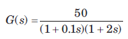
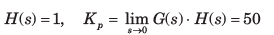
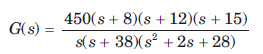
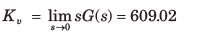
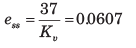
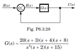
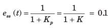
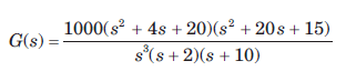
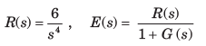
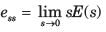
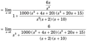
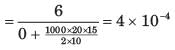
A ufb control system has a forward path transfer function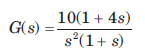 If the system is subjected to an input r(t) = 1 + t + 1/2 t2 , t > 0the steady state error of the system will be
- a)0
- b)0.1
- c)10
- d)∞
Correct answer is option 'C'. Can you explain this answer?
A ufb control system has a forward path transfer function
If the system is subjected to an input r(t) = 1 + t + 1/2 t2 , t > 0the steady state error of the system will be
a)
0
b)
0.1
c)
10
d)
∞
| | Lekshmi Kulkarni answered |
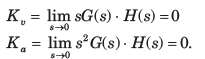
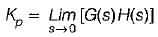
System is type 2. Therefore error due to 1+t would be zero and due to  would be
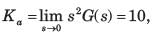
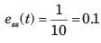
Note that you may calculate error from the formula
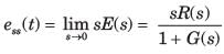
would be Note that you may calculate error from the formula

The steady-state error of a feedback control system with an acceleration input becomes finite in a- a)type-3 system
- b)type-2 system
- c)type-1 system
- d)type-0 system
Correct answer is option 'B'. Can you explain this answer?
The steady-state error of a feedback control system with an acceleration input becomes finite in a
a)
type-3 system
b)
type-2 system
c)
type-1 system
d)
type-0 system
| | Raj Choudhary answered |
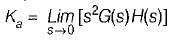
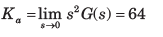
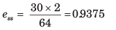
Steady state error with an acceleration input having an amplitude of A is given by

where,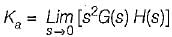
Hence, if the type of the system = 2, then Ka = some non-zero value or finite value due to which we will get some finite vaiue of Ka.
where,
Hence, if the type of the system = 2, then Ka = some non-zero value or finite value due to which we will get some finite vaiue of Ka.
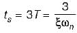
The time required for the response curve to reach and stay within the specified 2-5% of final value is referred to as :- a)Peak time
- b)Rise time
- c)Settling time
- d)Peak overshoot time
Correct answer is option 'C'. Can you explain this answer?
The time required for the response curve to reach and stay within the specified 2-5% of final value is referred to as :
a)
Peak time
b)
Rise time
c)
Settling time
d)
Peak overshoot time
| | Siddharth Malhotra answered |
Understanding Settling Time
Settling time is a critical parameter in control systems, particularly in the field of Electronics and Communication Engineering (ECE). It indicates how quickly a system can stabilize after a disturbance or a change in input.
Definition of Settling Time
- Settling time is defined as the time required for the system’s response curve to reach and remain within a specified percentage (usually 2-5%) of its final value after a step input is applied.
Importance of Settling Time
- Performance Indicator: Settling time is crucial for assessing the performance of control systems. A shorter settling time means the system responds quickly and efficiently to changes.
- Stability: It indicates how well the system can stabilize after fluctuations or disturbances, ensuring reliability in applications.
Comparison with Other Time Parameters
- Peak Time: This is the time it takes for the response to reach its first peak. It does not account for how long it takes to settle.
- Rise Time: This measures the time required for the response to rise from a specified lower percentage to a specified upper percentage of the final value.
- Peak Overshoot Time: This refers to the amount by which the response exceeds the final value before settling down.
Conclusion
- Settling time is key to evaluating a system's performance and stability. It ensures that after an input change, the system not only responds but also stays within acceptable limits of the final value, providing a clear indication of how effectively the system performs in real-world applications. Understanding this concept is essential for designing efficient control systems in ECE.
Which of the following is not true regarding addition of a pole to the forward-path transfer function?- a)Maximum overshoot of the closed-loop system is increased.
- b)Rise time of the step response is increased.
- c)Stability of the system is increased.
- d)Bandwidth of the system is reduced.
Correct answer is option 'C'. Can you explain this answer?
Which of the following is not true regarding addition of a pole to the forward-path transfer function?
a)
Maximum overshoot of the closed-loop system is increased.
b)
Rise time of the step response is increased.
c)
Stability of the system is increased.
d)
Bandwidth of the system is reduced.
| | Sandeep Chatterjee answered |
With addition of a pole to the forward-path transfer function, bandwidth will reduce.
Since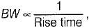 therefore rise time will increase.
Since rise time therefore stability will decrease.
Since
therefore rise time will increase.Since rise time
therefore stability will decrease.The peak overshoot of step-input response of an underdamped second-order system is an indication of- a)rise time of the system
- b)settling time of the system
- c)damping ratio of the system
- d)natural frequency of the system
Correct answer is option 'C'. Can you explain this answer?
The peak overshoot of step-input response of an underdamped second-order system is an indication of
a)
rise time of the system
b)
settling time of the system
c)
damping ratio of the system
d)
natural frequency of the system
| | Avik Iyer answered |
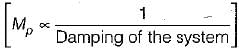
If damping of system increases, peak overshoot Mp decreases and vice-versa.
For type-2 system, the steady state error due to parabolic input is- a)finite
- b)zero
- c)infinite
- d)indeterminate
Correct answer is option 'A'. Can you explain this answer?
For type-2 system, the steady state error due to parabolic input is
a)
finite
b)
zero
c)
infinite
d)
indeterminate
| | Aman Jain answered |
For parabolic input,  (A = constant)
= Finite for type-2 system
So, ess = Some finite value
(A = constant)= Finite for type-2 system
So, ess = Some finite value
How can the steady state error can be reduced?- a)By decreasing the type of the system
- b)By increasing the input
- c)By decreasing the static error constant
- d)By increasing system gain
Correct answer is option 'D'. Can you explain this answer?
How can the steady state error can be reduced?
a)
By decreasing the type of the system
b)
By increasing the input
c)
By decreasing the static error constant
d)
By increasing system gain
| | Prisha Sengupta answered |
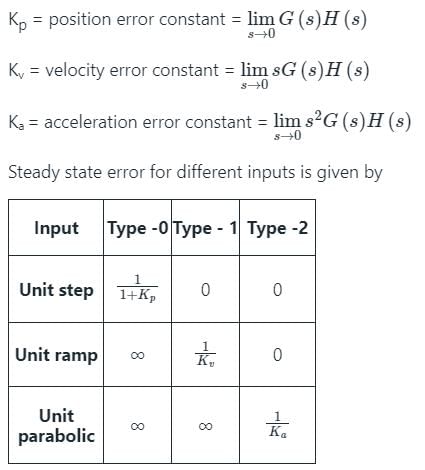
From the above table, it is clear that for type – 1 system, a system shows zero steady-state error for step-input, finite steady-state error for Ramp-input and ∞ steady-state error for parabolic-input.
As the type of the system increases, the steady-state error decreases.
The steady-state error is inversely proportional to the gain. Therefore, it can be reduced by increasing the system gain.
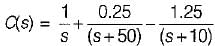
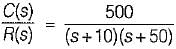
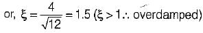
The unit step response of a system is given by c(t) - 1 + 0,25 e-50t - 1.25 er-10t The given system is- a)underdamped
- b)critically damped
- c)overdamped
- d)undamped
Correct answer is option 'C'. Can you explain this answer?
The unit step response of a system is given by c(t) - 1 + 0,25 e-50t - 1.25 er-10t The given system is
a)
underdamped
b)
critically damped
c)
overdamped
d)
undamped
| | Manoj Mehra answered |
Given, 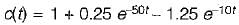
∴
or,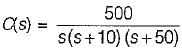
∴
or,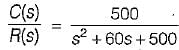
Thus,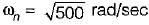
and
Thus,
Since, ξ > 1, therefore given system is overdamped.
∴
or,
∴
or,
Thus,
and
Thus,
Since, ξ > 1, therefore given system is overdamped.
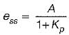
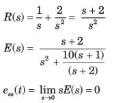
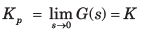
A system has position error constant Kp = 3. The steady state error for input of 8tu(t) is- a)2.67
- b)2
- c)∞
- d)0
Correct answer is option 'C'. Can you explain this answer?
A system has position error constant Kp = 3. The steady state error for input of 8tu(t) is
a)
2.67
b)
2
c)
∞
d)
0
| | Aryan Mathur answered |
Steady state error is a measure of how well a control system is able to track a desired input signal. It represents the difference between the desired output and the actual output of the system when the input signal has reached a steady state.
In this system, the position error constant Kp is given as 3. The position error constant relates the steady state error to the input signal. It is defined as the ratio of the steady state error to the input signal. Mathematically, Kp = 1 / steady state error.
Given that the input signal is 8tu(t), where u(t) is the unit step function, we can determine the steady state error using the position error constant.
Let's calculate the steady state error step by step:
1. First, we need to determine the Laplace transform of the input signal.
The Laplace transform of tu(t) is 1/s^2.
Therefore, the Laplace transform of 8tu(t) is 8/s^2.
2. Next, we determine the Laplace transform of the steady state error.
Let the Laplace transform of the steady state error be E(s).
Then, E(s) = Kp / (s * 8/s^2) = Kp * s^2 / 8.
3. To find the steady state error, we need to take the inverse Laplace transform of E(s).
Using inverse Laplace transform tables or software, we can determine that the inverse Laplace transform of Kp * s^2 / 8 is Kp/8 * t^2.
4. Since the input signal is a unit step function, the steady state error is the value of the inverse Laplace transform at t = infinity.
Therefore, the steady state error is Kp/8 * infinity^2 = Kp/8 * ∞ = 3/8 * ∞ = 0.
Hence, the correct answer is option 'C', which states that the steady state error is 0.
In time domain specification, the time delay is the time required for the response to reach- a)25% of final value
- b)50% of the final value
- c)10% of the final value
- d)63.3% of the final value
Correct answer is option 'B'. Can you explain this answer?
In time domain specification, the time delay is the time required for the response to reach
a)
25% of final value
b)
50% of the final value
c)
10% of the final value
d)
63.3% of the final value
| | Srestha Chavan answered |
Delay time (td) is the time required for the response curve to reach 50% of the final value.
Assertion (A): The "dominant pole" concept is used to control the dynamic performance of the system, whereas the “insignificant poles” are used for the purpose of. ensuring that the controller transfer function can be realized by physical components.
Reason (R): if the magnitude of the real part of a pole is atleast 5 to 10 times that of a dominant pole or a pair of complex dominant poles, the pole may be regarded as insignificant in so far as the transient response is concerned.- a)Both A and R are true and R is a correct explanation of A.
- b)Both A and R are true but R is not a correct explanation of A.
- c)A is true but R is false.
- d)A is false but R is true.
Correct answer is option 'B'. Can you explain this answer?
Assertion (A): The "dominant pole" concept is used to control the dynamic performance of the system, whereas the “insignificant poles” are used for the purpose of. ensuring that the controller transfer function can be realized by physical components.
Reason (R): if the magnitude of the real part of a pole is atleast 5 to 10 times that of a dominant pole or a pair of complex dominant poles, the pole may be regarded as insignificant in so far as the transient response is concerned.
Reason (R): if the magnitude of the real part of a pole is atleast 5 to 10 times that of a dominant pole or a pair of complex dominant poles, the pole may be regarded as insignificant in so far as the transient response is concerned.
a)
Both A and R are true and R is a correct explanation of A.
b)
Both A and R are true but R is not a correct explanation of A.
c)
A is true but R is false.
d)
A is false but R is true.
| | Devansh Das answered |
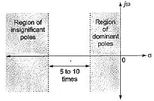
Both assertion and reason are true. However, the correct explanation of assertion is that the poles having real part magnitude 5 to 10 times of the magnitude of real part of dominant poles doesn't affect the transient response (dynamic performance) of the system to a great extent due to which they are termed as insignificant poies and hence are neglected for transient stability study purpose.
When the period of the observation is large, the type of the error will be:- a)Transient error
- b)Steady state error
- c)Half-power error
- d)Position error constant
Correct answer is option 'B'. Can you explain this answer?
When the period of the observation is large, the type of the error will be:
a)
Transient error
b)
Steady state error
c)
Half-power error
d)
Position error constant
| | Maulik Chatterjee answered |
Answer: b
Explanation: The error will be the steady state error if the period of observation is large as the time if large then the final value theorem can be directly applied.
Explanation: The error will be the steady state error if the period of observation is large as the time if large then the final value theorem can be directly applied.
The steady state error of a control system can be reduced by- a)increasing time constant of the system only.
- b)increasing gain constant of the system only.
- c)increasing both the time constant and gain of the system.
- d)none of the above.
Correct answer is option 'C'. Can you explain this answer?
The steady state error of a control system can be reduced by
a)
increasing time constant of the system only.
b)
increasing gain constant of the system only.
c)
increasing both the time constant and gain of the system.
d)
none of the above.
| | Anuj Kapoor answered |
Time constant of the system,

When is increased means damping is reduced, thus steady state error reduces.
Also, when gain of the system increases, then damping reduces and therefore, steady state error reduces.
When
is increased means damping is reduced, thus steady state error reduces.Also, when gain of the system increases, then damping reduces and therefore, steady state error reduces.
With negative feedback in a closed loop control system, the system sensitivity to parameter variation:- a)Increases
- b)Decreases
- c)Becomes zero
- d)Becomes infinite
Correct answer is option 'B'. Can you explain this answer?
With negative feedback in a closed loop control system, the system sensitivity to parameter variation:
a)
Increases
b)
Decreases
c)
Becomes zero
d)
Becomes infinite
| | Mahi Bose answered |
Answer: b
Explanation: Sensitivity is defined as the change in the output with respect to the change in the input and due to negative feedback reduces by a factor of 1/ (1+GH).
Explanation: Sensitivity is defined as the change in the output with respect to the change in the input and due to negative feedback reduces by a factor of 1/ (1+GH).
A third order system is approximated to an equivalent second order system. The rise time of this approximated lower order system will be:- a)Same as the original system for any input
- b)Smaller than the original system for any input
- c)Larger than the original system for any input
- d)Larger or smaller depending on the input
Correct answer is option 'B'. Can you explain this answer?
A third order system is approximated to an equivalent second order system. The rise time of this approximated lower order system will be:
a)
Same as the original system for any input
b)
Smaller than the original system for any input
c)
Larger than the original system for any input
d)
Larger or smaller depending on the input
| | Mansi Choudhury answered |
Answer: b
Explanation: As order of the system increases the system approaches more towards the ideal characteristics and if the third order system is approximated to an equivalent second order system then the rise time of this will be smaller than the original system for any input.
Explanation: As order of the system increases the system approaches more towards the ideal characteristics and if the third order system is approximated to an equivalent second order system then the rise time of this will be smaller than the original system for any input.
Consider the following statements related to second order control system with unit step input:
1. The right-half s-plane corresponds to negative damping.
2. Negative damping gives a response that doesn’t grows in magnitude without bound with time.
3. The imaginary axis corresponds to zero damping.
4. The maximum overshoot is often used to measure the relative stability of a control system.
5. Higher the damping in the system larger is the peak overshoot in the transient response of the system.
Which of the above statements is/are correct?- a)1 and 3
- b)1, 4 and 5
- c)2, 3 and 4
- d)1,3 and 4
Correct answer is option 'D'. Can you explain this answer?
Consider the following statements related to second order control system with unit step input:
1. The right-half s-plane corresponds to negative damping.
2. Negative damping gives a response that doesn’t grows in magnitude without bound with time.
3. The imaginary axis corresponds to zero damping.
4. The maximum overshoot is often used to measure the relative stability of a control system.
5. Higher the damping in the system larger is the peak overshoot in the transient response of the system.
Which of the above statements is/are correct?
a)
1 and 3
b)
1, 4 and 5
c)
2, 3 and 4
d)
1,3 and 4
| | Vaibhav Joshi answered |
Negative damping gives a response that grows in magnitude without bound in time. Hence, statement-2 is false.
Since therefore higher is the damping
in the system, less is the peak overshoot of the system. Hence, statement-5 is not correct
Since
therefore higher is the dampingin the system, less is the peak overshoot of the system. Hence, statement-5 is not correct
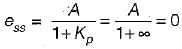
For a type one system, the steady-state error due to step input is equal to- a)zero
- b)0.75
- c)infinite
- d)0.50
Correct answer is option 'A'. Can you explain this answer?
For a type one system, the steady-state error due to step input is equal to
a)
zero
b)
0.75
c)
infinite
d)
0.50
| | Mahesh Datta answered |
where,
(Here, A = magnitude of step input) Since system is type -1, therefore Kp = ∞
∴
The unit impulse response of a linear time invariant second order system is
g(t) = 10e-8t sin 6t (t > C)
The natural frequency and the damping ratio of the system are respectively - a)10 rad/sec and 0.6
- b)10 rad/sec and 0.8
- c)5 rad/sec and 0.6
- d)6 rad/sec and 0.8
Correct answer is option 'B'. Can you explain this answer?
The unit impulse response of a linear time invariant second order system is
g(t) = 10e-8t sin 6t (t > C)
The natural frequency and the damping ratio of the system are respectively
g(t) = 10e-8t sin 6t (t > C)
The natural frequency and the damping ratio of the system are respectively
a)
10 rad/sec and 0.6
b)
10 rad/sec and 0.8
c)
5 rad/sec and 0.6
d)
6 rad/sec and 0.8
| | Bijoy Nair answered |
Given, c(t) = g(t) = 10e-8t sin6t
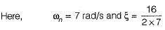
Here,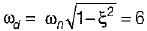
and ξωn = 8
or,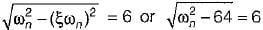
or,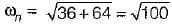
= 10 rad/sec
So,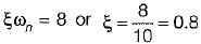
Here,
and ξωn = 8
or,
or,
= 10 rad/sec
So,
A second order system is said to be critically damped if the damping factor (ξ) is - a)ξ= 0.707
- b)ξ<1
- c)ξ=1
- d)ξ>1
Correct answer is option 'C'. Can you explain this answer?
A second order system is said to be critically damped if the damping factor (ξ) is
a)
ξ= 0.707
b)
ξ<1
c)
ξ=1
d)
ξ>1
| | Priyanka Ahuja answered |
If ξ < 1, system is underdamped.
If ξ > 1, system is overdamped.
If ξ= 1, system is critically damped.
If ξ > 1, system is overdamped.
If ξ= 1, system is critically damped.
An underdamped second order system with negative damping will have the roots :- a)On the negative real axis as roots
- b)On the left hand side of complex plane as complex roots
- c)On the right hand side of complex plane as complex conjugates
- d)On the positive real axis as real roots
Correct answer is option 'C'. Can you explain this answer?
An underdamped second order system with negative damping will have the roots :
a)
On the negative real axis as roots
b)
On the left hand side of complex plane as complex roots
c)
On the right hand side of complex plane as complex conjugates
d)
On the positive real axis as real roots
| | Rithika Pillai answered |
Answer: c
Explanation: An underdamped second order system is the system which has damping factor less than unity and with negative damping will have the roots on the right hand side of complex plane as complex conjugates.
Explanation: An underdamped second order system is the system which has damping factor less than unity and with negative damping will have the roots on the right hand side of complex plane as complex conjugates.
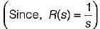
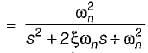
When the unit step response of a unity feedback control system having forward path transfer function G (s) =80/s(s+18)?- a)Overdamped
- b)Critically damped
- c)Under damped
- d)Un Damped oscillatory
Correct answer is option 'A'. Can you explain this answer?
When the unit step response of a unity feedback control system having forward path transfer function G (s) =80/s(s+18)?
a)
Overdamped
b)
Critically damped
c)
Under damped
d)
Un Damped oscillatory
| | Poulomi Ahuja answered |
Answer: a
Explanation: The open loop transfer function is first converted into the closed loop as unity feedback is used and then value of damping factor is calculated.
Explanation: The open loop transfer function is first converted into the closed loop as unity feedback is used and then value of damping factor is calculated.
The identical first order system have been cascaded non-interactively. The unit step response of the systems will be:- a)Overdamped
- b)Underdamped
- c)Undamped
- d)Critically damped
Correct answer is option 'D'. Can you explain this answer?
The identical first order system have been cascaded non-interactively. The unit step response of the systems will be:
a)
Overdamped
b)
Underdamped
c)
Undamped
d)
Critically damped
| | Kalyan Patel answered |
Answer: d
Explanation: Since both the systems that is the first order systems are cascaded non-interactively, the overall unit step response will be critically damped.
Explanation: Since both the systems that is the first order systems are cascaded non-interactively, the overall unit step response will be critically damped.
A system has a single pole at origin. Its impulse response will be:- a)Constant
- b)Ramp
- c)Decaying exponential
- d)Oscillatory
Correct answer is option 'A'. Can you explain this answer?
A system has a single pole at origin. Its impulse response will be:
a)
Constant
b)
Ramp
c)
Decaying exponential
d)
Oscillatory
| | Avik Saha answered |
Answer: a
Explanation: For a single pole at origin the system is of type 1 and impulse response of the system with single pole at the origin will be constant.
Explanation: For a single pole at origin the system is of type 1 and impulse response of the system with single pole at the origin will be constant.

Assertion (A): With the increase in bandwidth of the system the response of the system becomes fast.
Reason (R): Damping ratio of the system decreases with the increase in bandwidth.- a)Both A and R are true and R is a correct explanation of A.
- b)Both A and R are true but R is not a correct explanation of A.
- c)A is true but R is false.
- d)A is false but R is true.
Correct answer is option 'B'. Can you explain this answer?
Assertion (A): With the increase in bandwidth of the system the response of the system becomes fast.
Reason (R): Damping ratio of the system decreases with the increase in bandwidth.
Reason (R): Damping ratio of the system decreases with the increase in bandwidth.
a)
Both A and R are true and R is a correct explanation of A.
b)
Both A and R are true but R is not a correct explanation of A.
c)
A is true but R is false.
d)
A is false but R is true.
| | Mayank Sengupta answered |
Explanation:
The statement "With the increase in bandwidth of the system the response of the system becomes fast" is true because bandwidth is a measure of the frequency range that a system can handle. A system with a higher bandwidth can handle higher frequency signals, and thus respond faster to changes in the input signal.
However, the statement "Damping ratio of the system decreases with the increase in bandwidth" is not always true. The damping ratio is a measure of how quickly the system oscillations decay in response to an input. It is related to the natural frequency of the system and the amount of damping in the system.
Counterexample:
Consider a system with a low damping ratio and a high natural frequency. This system will have a high bandwidth because it can respond to high-frequency signals. However, the damping ratio is low, meaning that the system will oscillate for a long time before settling to a steady-state response. Therefore, in this case, the response of the system is not necessarily fast even though the bandwidth is high.
Conclusion:
Therefore, both statements are true, but the second statement does not always provide a correct explanation for the first statement. The relationship between bandwidth and response time is more complex and depends on other factors such as the damping ratio and natural frequency of the system.
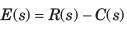
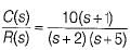
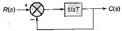
In the system shown in fig. r(t) = 1 + 2t , t > 0 .The steady state error e(t) is equal to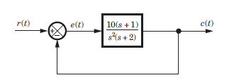
- a)1/5
- b)5
- c)0
- d)∞
Correct answer is option 'C'. Can you explain this answer?
In the system shown in fig. r(t) = 1 + 2t , t > 0 .The steady state error e(t) is equal to
a)
1/5
b)
5
c)
0
d)
∞
| | Deepika Deshpande answered |
The system is type 2. Thus to step and ramp input error will be zero.
The system with the open loop transfer function 1/s(1+s) is:- a)Type 2 and order 1
- b)Type 1 and order 1
- c)Type 0 and order 0
- d)Type 1 and order 2
Correct answer is option 'D'. Can you explain this answer?
The system with the open loop transfer function 1/s(1+s) is:
a)
Type 2 and order 1
b)
Type 1 and order 1
c)
Type 0 and order 0
d)
Type 1 and order 2
| | Kajal Yadav answered |
Answer: d
Explanation: Type is defined as the number of poles at origin and order is defined as the total number of poles and this is calculated with the help of the transfer function from the above transfer function the type is 1 and order is 2.
Explanation: Type is defined as the number of poles at origin and order is defined as the total number of poles and this is calculated with the help of the transfer function from the above transfer function the type is 1 and order is 2.
The damping ratio of a system having the characteristic equation s2 + 2s + 8 = 0 is- a)0.300 (underdamped)
- b)0.353 (underdamped)
- c)1.24 (overdamped)
- d)1.02 (overdamped)
Correct answer is option 'B'. Can you explain this answer?
The damping ratio of a system having the characteristic equation s2 + 2s + 8 = 0 is
a)
0.300 (underdamped)
b)
0.353 (underdamped)
c)
1.24 (overdamped)
d)
1.02 (overdamped)
| | Nikhil Iyer answered |
Given, s2 + 2s + 8 = 0
Here, ωn = √8 rad/s = 2√2 rad/sec
and
or,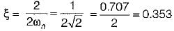
Since, therefore
system is underdamped.
Here, ωn = √8 rad/s = 2√2 rad/sec
and
or,
Since,
thereforesystem is underdamped.
If a type 0 system is subjected to step input, what is its effect on steady state error?- a) It increases continuously
- b) It remains constant
- c) It decreases monotonically
- d) It gets subjected to another input
Correct answer is option 'B'. Can you explain this answer?
If a type 0 system is subjected to step input, what is its effect on steady state error?
a)
It increases continuously
b)
It remains constant
c)
It decreases monotonically
d)
It gets subjected to another input
| | Shaan Choudhary answered |
Introduction:
A system's steady-state error is the difference between the desired output and the actual output of the system when it reaches a stable condition. In this case, we are considering a type 0 system, which means that the steady-state error is determined by the input to the system.
Effect of a Step Input:
When a step input is applied to a type 0 system, the output of the system gradually approaches the desired value over time. The response of a type 0 system to a step input can be represented by a ramp function.
Explanation:
The steady-state error of a type 0 system is defined as the difference between the desired value and the output value when the system reaches a stable condition. In the case of a step input, the desired value is constant over time.
Initially, when the step input is applied, the output of the system starts to change. As time progresses, the output approaches the desired value, and the steady-state error decreases. Eventually, when the system reaches a stable condition, the output value becomes equal to the desired value, resulting in zero steady-state error.
Since the desired value remains constant throughout the response of a type 0 system to a step input, the steady-state error also remains constant. This is because once the system reaches a stable condition, the output value doesn't change further, and the steady-state error is determined solely by the difference between the desired value and the output value at that point.
Conclusion:
In summary, when a type 0 system is subjected to a step input, the steady-state error remains constant. This is because the output of the system eventually reaches a stable condition where it matches the desired value, resulting in zero steady-state error.
For a second-order prototype system, when the undamped natural frequency is increased, the maximum overshoot of the output will- a)increase
- b)remains the same
- c)decrease
- d)increase or decrease depending on the value of damping factor of the system
Correct answer is option 'B'. Can you explain this answer?
For a second-order prototype system, when the undamped natural frequency is increased, the maximum overshoot of the output will
a)
increase
b)
remains the same
c)
decrease
d)
increase or decrease depending on the value of damping factor of the system
| | Palak Verma answered |
We know that, maximum overshot is

Mp is independent of wn. So Mp ∝ ξ only.
Mp is independent of wn. So Mp ∝ ξ only.
Given a unity feedback system with G (s) =K/ s (s+4). What is the value of K for a damping ratio of 0.5?- a)1
- b)16
- c)4
- d)2
Correct answer is option 'B'. Can you explain this answer?
Given a unity feedback system with G (s) =K/ s (s+4). What is the value of K for a damping ratio of 0.5?
a)
1
b)
16
c)
4
d)
2
| | Jatin Mukherjee answered |
Answer: b
Explanation: Comparing the equation with the standard characteristic equation gives the value of damping factor, natural frequency and value of gain K.
Explanation: Comparing the equation with the standard characteristic equation gives the value of damping factor, natural frequency and value of gain K.
The steady-state error coefficients for a system are Kp = ∞ , Kv = finite constant and Ka = 0. The type of the system is- a)4
- b)2
- c)1
- d)0
Correct answer is option 'C'. Can you explain this answer?
The steady-state error coefficients for a system are Kp = ∞ , Kv = finite constant and Ka = 0. The type of the system is
a)
4
b)
2
c)
1
d)
0
| | Abhishek Chauhan answered |
We have, 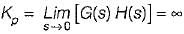
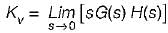
= finite constant
and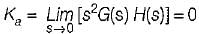
From above values of Kp, Kv and Ka we conclude that the type of the system should be one.
= finite constant
and
From above values of Kp, Kv and Ka we conclude that the type of the system should be one.
Consider a causal second-order system with the transfer function 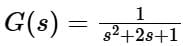 with a unit-step
 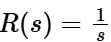 as an input. Let c(s) be the corresponding output. The time taken by the system output c(t) to reach 94% of its steady-state value
 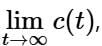 rounded off to two decimal places, is
 - a)5.25
- b)2.81
- c)4.50
- d)3.89
Correct answer is option 'C'. Can you explain this answer?
Consider a causal second-order system with the transfer function with a unit-step as an input. Let c(s) be the corresponding output. The time taken by the system output c(t) to reach 94% of its steady-state value rounded off to two decimal places, is
with a unit-step as an input. Let c(s) be the corresponding output. The time taken by the system output c(t) to reach 94% of its steady-state value rounded off to two decimal places, is a)
5.25
b)
2.81
c)
4.50
d)
3.89
 | Imtiaz Ahmad answered |
Concept:
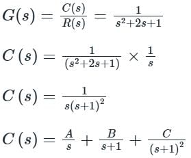
A = 1
B = -1
C = -1
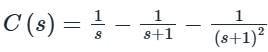
Applying inverse Laplace transform:
C(t) = 1 – e-t – te-t
at steady state i.e. at t → ∞
C(t) = 1
94% of steady state = 94/100 x 1
= 0.94.
0.94 = 1 – e-t – te-t
Substitute all options
Let us substitute options
option (a) t= 5.25
1 – e-5.25 – 5.25 e-5.25
= 0.967
option (b)
t = 4.50
1 – 0.938
≈ 0.94
A = 1
B = -1
C = -1
Applying inverse Laplace transform:
C(t) = 1 – e-t – te-t
at steady state i.e. at t → ∞
C(t) = 1
94% of steady state = 94/100 x 1
= 0.94.
0.94 = 1 – e-t – te-t
Substitute all options
Let us substitute options
option (a) t= 5.25
1 – e-5.25 – 5.25 e-5.25
= 0.967
option (b)
t = 4.50
1 – 0.938
≈ 0.94


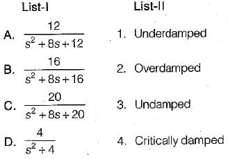
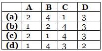
Match List - I (Transfer function of systems) with List - II (Nature of damping) and select the correct answer using the codes given below the lists:
Codes:
- a)a
- b)b
- c)c
- d)d
Correct answer is option 'A'. Can you explain this answer?
Match List - I (Transfer function of systems) with List - II (Nature of damping) and select the correct answer using the codes given below the lists:
Codes:
Codes:
a)
a
b)
b
c)
c
d)
d
| | Ameya Gupta answered |
Characteristic equations are:
• s2 + 8s + 1 2 = 0
Here, ωn = √12 and
• s2 + 8s + 16 = 0
Here, ωn = 4 and 2 ξωn = 8
or, ξ = 1 (critically damped)
• s2 + 8s + 20 = 0
Here, ωn = √20
and 2ξωn = 8
or, ξ = 0.894 (ξ < 1 ∴ underdamped)
• s2 + 4 = 0
or, ωn = 2
and ξ = 0 (∴ undamped)
• s2 + 8s + 1 2 = 0
Here, ωn = √12 and
• s2 + 8s + 16 = 0
Here, ωn = 4 and 2 ξωn = 8
or, ξ = 1 (critically damped)
• s2 + 8s + 20 = 0
Here, ωn = √20
and 2ξωn = 8
or, ξ = 0.894 (ξ < 1 ∴ underdamped)
• s2 + 4 = 0
or, ωn = 2
and ξ = 0 (∴ undamped)
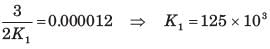
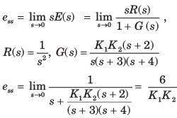
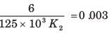
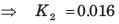
For the system shown in fig.the steady state error component due to unit step disturbance is 0.000012 and steady state error component due to unit ramp input is 0.003. The values of K1 and K2 are respectively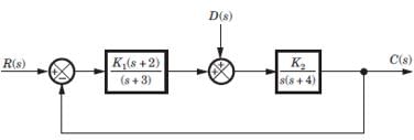
- a)16.4, 1684
- b)1250, 2.4
- c)125 x 103, 0.016
- d)463, 3981
Correct answer is option 'C'. Can you explain this answer?
For the system shown in fig.the steady state error component due to unit step disturbance is 0.000012 and steady state error component due to unit ramp input is 0.003. The values of K1 and K2 are respectively
a)
16.4, 1684
b)
1250, 2.4
c)
125 x 103, 0.016
d)
463, 3981
 | Prashanth Rane answered |
If R (s) = 0
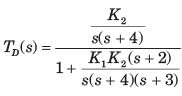
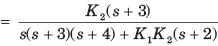
Error in output due to disturbance
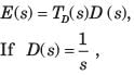
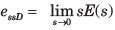
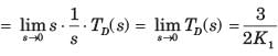
Error due to ramp input
Error in output due to disturbance
Error due to ramp input
The transient response of a system is mainly due to- a)internal forces
- b)stored energy
- c)friction
- d)external forces
Correct answer is option 'B'. Can you explain this answer?
The transient response of a system is mainly due to
a)
internal forces
b)
stored energy
c)
friction
d)
external forces
| | Abhishek Chauhan answered |
Transient response of a system in Electrical Engineering
Transient response is the response of a system when it is subjected to a sudden change in its input or operating conditions. It is a temporary response that eventually settles down to a steady-state response. In electrical engineering, transient response is an important concept that is used to analyze the behavior of electrical systems. The transient response of a system is mainly due to stored energy.
Stored Energy
In electrical systems, energy can be stored in various forms such as electrical, magnetic, or mechanical. When there is a sudden change in the input or operating conditions of a system, this stored energy is released and causes a transient response. For example, when a capacitor is suddenly charged, it stores electrical energy. When the input voltage is removed, this stored energy is discharged and causes a transient response.
Effect of stored energy on transient response
The effect of stored energy on transient response can be understood by considering the example of a simple RC circuit. When a step voltage is applied to the circuit, the capacitor starts charging and stores electrical energy. As the capacitor charges, the voltage across it increases and the current through the resistor decreases. This causes a transient response in the circuit. Eventually, the capacitor reaches its fully charged state and the steady-state response is achieved.
Conclusion
In conclusion, the transient response of a system in electrical engineering is mainly due to stored energy. When there is a sudden change in the input or operating conditions of a system, the stored energy is released and causes a transient response. Understanding the effect of stored energy on transient response is important for analyzing the behavior of electrical systems.

A linear second-order system with the transfer function G(s) =  is initially at rest and is subjected to a step input signal.
The response of the system will exhibit a peak overshoot of- a)25%
- b)0%
- c)2%
- d)none of these
Correct answer is option 'B'. Can you explain this answer?
A linear second-order system with the transfer function G(s) = is initially at rest and is subjected to a step input signal.
The response of the system will exhibit a peak overshoot of
is initially at rest and is subjected to a step input signal.The response of the system will exhibit a peak overshoot of
a)
25%
b)
0%
c)
2%
d)
none of these
| | Lekshmi Choudhary answered |

Since ξ > 1, therefore the system is overdamped. Hence, there will be no peak overshoot in the output response of the system.
The closed-loop transfer function of a system is
Which of the following statements is not true?- a)The system is non-oscillatory.
- b)The closed-loop frequency response of this system exhibits a resonance peak.
- c)The damping ratio of the closed-loop poles is less than unity.
- d)The unit step response exhibits overshoot due to the presence of a zero.
Correct answer is option 'C'. Can you explain this answer?
The closed-loop transfer function of a system is
Which of the following statements is not true?
Which of the following statements is not true?
a)
The system is non-oscillatory.
b)
The closed-loop frequency response of this system exhibits a resonance peak.
c)
The damping ratio of the closed-loop poles is less than unity.
d)
The unit step response exhibits overshoot due to the presence of a zero.
| | Naveen Sharma answered |
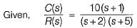
It’s characteristic equation is (s + 2) (s + 5) = 0
or, s2 + 7s +10 = 0
Thus, damping ratio ξ > 1.
Hence, option (c) is false.
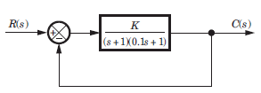


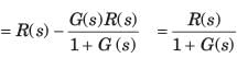
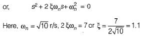
Consider a unity feedback control system as shown in figure below:
 The error signal e(t) for a unit ramp input for T > 0 is
- a)T
- b)T - e-t/T
- c)T(1 - e-t/T)
- d) t + T . e-t/T
Correct answer is option 'C'. Can you explain this answer?
Consider a unity feedback control system as shown in figure below:
The error signal e(t) for a unit ramp input for T > 0 is
a)
T
b)
T - e-t/T
c)
T(1 - e-t/T)
d)
t + T . e-t/T
| | Abhay Khanna answered |
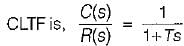
Given,
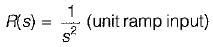
∴
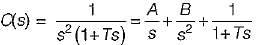
Here, A = -T, 6 = 1, C = T2
So,
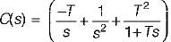
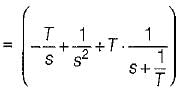
Taking inverse Laplace transform on both sides, we get:
C(t) = (-T + t + Te-t/T)
∴ Error signal,
e(t) = c(t) - r(t)
= c(t) - t = - T + Te-t/T
= T(1 - e-t/T)
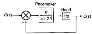
The block diagram of an electronic pacemaker is given in figure below.
What is the value of K for which the steady-state error to a unit ramp input is 0.02?- a)10
- b)100
- c)103
- d)1
Correct answer is option 'C'. Can you explain this answer?
The block diagram of an electronic pacemaker is given in figure below.
What is the value of K for which the steady-state error to a unit ramp input is 0.02?
What is the value of K for which the steady-state error to a unit ramp input is 0.02?
a)
10
b)
100
c)
103
d)
1
| | Dhruv Datta answered |
Here, 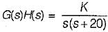
As the input is a unit ramp function, therefore
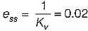
Now,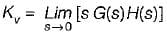
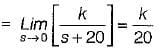
∴
or,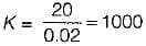
As the input is a unit ramp function, therefore
Now,
∴
or,
A system has the following transfer function The type and order of the system are respectively
- a)7 and 5
- b)4 and 5
- c)4 and 7
- d)7 and 4
Correct answer is option 'C'. Can you explain this answer?
A system has the following transfer function
The type and order of the system are respectively
a)
7 and 5
b)
4 and 5
c)
4 and 7
d)
7 and 4
 | Sagnik Sen answered |
The s has power of 4 and denominator has order of 7. So Type 4 and Order 7.
A second order system has a closed loop transfer function 
If the system is initially at rest and subjected to a unit step input at t = 0, the third peak in the response will occur at- a)

- b)πsec.
- c)

- d)1 πsec.
Correct answer is option 'C'. Can you explain this answer?
A second order system has a closed loop transfer function
If the system is initially at rest and subjected to a unit step input at t = 0, the third peak in the response will occur at
If the system is initially at rest and subjected to a unit step input at t = 0, the third peak in the response will occur at
a)
b)
πsec.
c)
d)
1 πsec.
| | Ishan Chawla answered |
Here,
or,
Peak time,
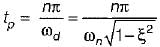
For 3rd peak, n = 5
(3rd overshoot is the third peak)
So,

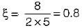
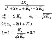
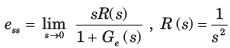
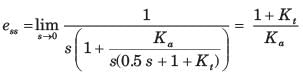
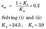
Block diagram of a position control system is shown in fig.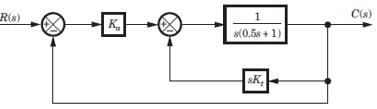 If the damping ratio of the system is increased to 0.7 without affecting the steady state error, then thevalue of Ka and Kt are
- a)86, 12.8
- b)49, 9.3
- c)24.5, 3.9
- d)43, 6.4
Correct answer is option 'C'. Can you explain this answer?
Block diagram of a position control system is shown in fig.
If the damping ratio of the system is increased to 0.7 without affecting the steady state error, then thevalue of Ka and Kt are
a)
86, 12.8
b)
49, 9.3
c)
24.5, 3.9
d)
43, 6.4
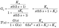
| | Prashanth Rane answered |
The equivalent open-loop transfer function
Chapter doubts & questions for Time Response Analysis - 6 Months Preparation for GATE Electrical 2026 is part of Electrical Engineering (EE) exam preparation. The chapters have been prepared according to the Electrical Engineering (EE) exam syllabus. The Chapter doubts & questions, notes, tests & MCQs are made for Electrical Engineering (EE) 2026 Exam. Find important definitions, questions, notes, meanings, examples, exercises, MCQs and online tests here.
Chapter doubts & questions of Time Response Analysis - 6 Months Preparation for GATE Electrical in English & Hindi are available as part of Electrical Engineering (EE) exam. Download more important topics, notes, lectures and mock test series for Electrical Engineering (EE) Exam by signing up for free.
6 Months Preparation for GATE Electrical675 videos|1390 docs|885 tests |