


All Exams > Electrical Engineering (EE) > 6 Months Preparation for GATE Electrical > All Questions
All questions of Measurement & Resistance for Electrical Engineering (EE) Exam
Which of the following are examples of measurement of high resistance?- a)Insulation resistance
- b)Leakage resistance
- c)Vacuum tube circuit
- d)All of the above
Correct answer is option 'D'. Can you explain this answer?
Which of the following are examples of measurement of high resistance?
a)
Insulation resistance
b)
Leakage resistance
c)
Vacuum tube circuit
d)
All of the above
 | Gate Gurus answered |
Measurement of high resistance:
We knew that the resistance with a value above 100 kΩ is considered as high resistance. The measurement of high resistance of the order of hundreds and thousands of megaohms is often required in electrical equipment. The example of such resistances are as follows:
(a) The insulation resistance of various components like machines and cables.
(b) Voltage coefficient testing of resistors and leakage resistance measurements of capacitors
(c) Resistance of high circuit elements like vacuum tube circuits.
(d) Volume resistivity of a material, i.e, the resistance between two faces of unit area separated by unit distance with all conduction from face to face is through the body of the material.
(e) Surface resistivity, i.e., the resistance between two lines of unit length and unit distance apart, the lines being on the surface of the material and all conduction being on the surface.

Which of the following statement is NOT correct?
- a)Four terminal is required for measurement of low resistance
- b)For measurement of medium resistance only two terminal is required
- c)To measure high resistance, three terminal is required
- d)To measure high resistance, only one terminal is required
Correct answer is option 'D'. Can you explain this answer?
Which of the following statement is NOT correct?
a)
Four terminal is required for measurement of low resistance
b)
For measurement of medium resistance only two terminal is required
c)
To measure high resistance, three terminal is required
d)
To measure high resistance, only one terminal is required
 | Pioneer Academy answered |
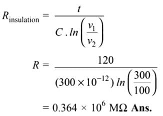
A length of cable was tested for insulation resistance using the loss of charge method. A capacitance formed by the sheath of cable of 300 pF is found to have a drop-in voltage from 300 V to 100 V in 120 seconds. What will 1. be the insulation resistance of the cable.- a)0.84 × 10⁶ MΩ
- b)0.364 × 10⁶ MΩ
- c)0.182 × 10⁶ MΩ
- d)0.112 × 10⁶ MΩ
Correct answer is option 'B'. Can you explain this answer?
A length of cable was tested for insulation resistance using the loss of charge method. A capacitance formed by the sheath of cable of 300 pF is found to have a drop-in voltage from 300 V to 100 V in 120 seconds. What will 1. be the insulation resistance of the cable.
a)
0.84 × 10⁶ MΩ
b)
0.364 × 10⁶ MΩ
c)
0.182 × 10⁶ MΩ
d)
0.112 × 10⁶ MΩ
| | Pioneer Academy answered |
Which of the following statement is incorrect while taking precautions for testing the cable using the direct deflection method?- a)Low-value resistance should be used with a galvanometer
- b)Galvanometer should be properly shunted
- c)Galvanometer should have high resistance
- d)The cable should be immersed for 24 hours
Correct answer is option 'A'. Can you explain this answer?
Which of the following statement is incorrect while taking precautions for testing the cable using the direct deflection method?
a)
Low-value resistance should be used with a galvanometer
b)
Galvanometer should be properly shunted
c)
Galvanometer should have high resistance
d)
The cable should be immersed for 24 hours
| | Gate Gurus answered |
(a) The direct deflection method is used for the measurement of the insulation resistance of the cable. Following precautions should be taken while using the direct deflection method.
(b) Before testing the cable is immersed in water at least for 24 hours. The temperature of the water is maintained constant. The water enters through the pores if any, and soaks through the defects, and at the same time, the cable attains the temperature of the water.
(c) In the earlier phase of the measurement, the galvanometer must be properly shunted. It includes a series resistance of high value. The true value of insulation resistance can be determined by subtracting the value of series resistance from the observed resistance.
(d) While conducting tests on cables the galvanometer should be short-circuited before applying the voltage. The short-circuiting connection is removed only after sufficient time has elapsed so that charging and absorption currents cease to flow.
(e) After the application of voltage, a short circuit connection across the galvanometer is removed. Thus galvanometer is protected from the sudden initial spike of current which charges cable which acts as a capacitor.
(f) The battery voltage should be around 500 V and should be maintained constant. The galvanometer should be highly sensitive (not less than 1000 mm per microampere at a scale distance of 1 metre), should have high resistance and also that its deflection should be directly proportional to the current flowing through it and should be critically damped.
(g) To prevent leakage currents, the galvanometer circuit switches and circuitry must be well insulated.
The problem faced while measuring high resistance is/are- a)Leakage current
- b)Stray charge
- c)Requirement of high voltage
- d)All of the above
Correct answer is option 'A'. Can you explain this answer?
The problem faced while measuring high resistance is/are
a)
Leakage current
b)
Stray charge
c)
Requirement of high voltage
d)
All of the above
| | Pooja Patel answered |
Problems in Measurement of High Resistance:
There are some problems and difficulties that occurred in the measurement of high resistance. Due to very high resistance, a very small current flows through the measuring circuits, which is very difficult to sense. The various problem and difficulties are as follows:
1. Leakage Currents: The leakage current is produced and is of comparable magnitude to the current being measured. Such currents cause errors. These currents depend on humidity and hence are unpredictable. Hence leakage currents must be eliminated from the measurement.
2. The stray charges may appear due to the electrostatic effect such charges and alternating fields can also cause serious measurement errors.
3. One point of the circuit may be connected to the earth for accuracy in measurements.
4. When the voltage is applied to the insulation resistance, it takes some time for charging and absorbing currents. The measurement should be delayed till these current vanish completely. In some cases, this may take a very long time hence the testing conditions include the time between the application of voltage and the observation of the reading.
5. A very high voltage is required in order to raise the current magnitudes. The galvanometer should be very sensitive and proper steps must be taken to prevent the damage of the galvanometer due to high voltages.
Which of the following method is most widely used for insulation resistance of the cable?- a)Loss of charge method
- b)Mega Ohm bridge method
- c)Direct deflection method
- d)None of the above
Correct answer is option 'C'. Can you explain this answer?
Which of the following method is most widely used for insulation resistance of the cable?
a)
Loss of charge method
b)
Mega Ohm bridge method
c)
Direct deflection method
d)
None of the above
| | Gate Gurus answered |
The direct deflection method is used for high resistance measurement. In such method, a high resistance about 1 kΩ or more) and very sensitive moving coil galvanometer is connected in series with the resistance to be measured along with supply voltage as shown in Fig.
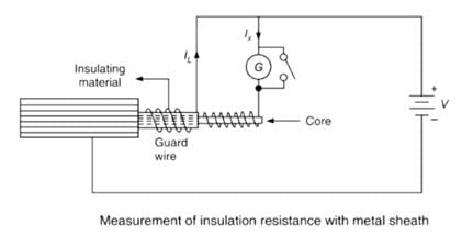
The deflection of the galvanometer gives a measure of the insulation resistance. This method is widely used for measuring the insulation resistance of the cable.
The deflection of the galvanometer gives a measure of the insulation resistance. This method is widely used for measuring the insulation resistance of the cable.
When a capacitor was connected across the terminals of an ohm meter, the pointer indicated a low resistance initially and then slowly came back to very high resistance. This indicates that capacitor is- a)Faulty
- b)All right
- c)Leaky
- d)Short-circuited
Correct answer is option 'B'. Can you explain this answer?
When a capacitor was connected across the terminals of an ohm meter, the pointer indicated a low resistance initially and then slowly came back to very high resistance. This indicates that capacitor is
a)
Faulty
b)
All right
c)
Leaky
d)
Short-circuited
| | Pooja Patel answered |
Concept:
Capacitor behavior:
- Ohmmeter uses dc voltage (battery) to measure the unknown resistance.
- Then the capacitor is subjected to dc source, initially, it acts as a short circuit and at steady-state, it acts as an open circuit.
- At the time when the ohmmeter is connected to the capacitor, the capacitor acts as a short circuit, so low resistance is indicated.
- After some time, the capacitor behaves as an open-circuit, so the pointer moves to the final position.
- This states that the capacitor is in very good condition to be used.
Important Points
- Capacitive reactance is given by Xc = 1/(2πfc) where f = frequency and c = value of capacitance
- Frequency f = 1/T (Time period)
- At the instant when the capacitor is connected to dc source, then V volt is reached in 0 sec so the time period is 0 sec.
- This makes the frequency to be infinity, therefore capacitive reactance becomes zero.
- That's why the capacitor acts as a short circuit initially when the dc source is applied.
- Now capacitor starts charging and voltage is developed across it.
- When the steady-state voltage across the capacitor is equal to source voltage, then after that it doesn't allow any current to pass through it.
- Therefore, acts as highly resistive or this can also be seen when at steady-state, frequency is zero, so capacitive reactance becomes infinity.
- That's why the capacitor blocks dc at the steady-state condition.
______ eliminates errors due to contacts and ______ in bridge measuring instruments.- a)Wheatstone Bridge, lead capacitances
- b)Kelvin's Double bridge, lead resistances
- c)Wheatstone bridge, lead inductances
- d)Wheatstone Bridge, lead resistances
Correct answer is option 'B'. Can you explain this answer?
______ eliminates errors due to contacts and ______ in bridge measuring instruments.
a)
Wheatstone Bridge, lead capacitances
b)
Kelvin's Double bridge, lead resistances
c)
Wheatstone bridge, lead inductances
d)
Wheatstone Bridge, lead resistances
| | Pooja Patel answered |
Kelvin's Double bridge:
- Kelvin Bridge is a modified Wheatstone bridge and provides high accuracy especially in the measurement of low resistance below 1 Ω.
- The error introduced by the contact/lead resistance is quite large and hence, will give an inaccurate reading if measured through a Wheatstone bridge.
- In order to avoid this problem, Kelvin's double bridge is used. It is so constructed that the contact resistance will not come into the picture while measuring the value of low resistance.
Advantages:
- It can measure the resistance value in the range of 0.1 µA to 1.0 A.
- Power consumption is less.
- Simple in construction.
- Sensitivity is high.
Construction:
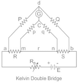
- The Kelvin double bridge uses a second set of ratio arms, which is why it is called a "double bridge" and has low resistance arms with four terminal resistors. The first ratio of the arm is P and Q, and the second ratio of the arm is p and q.
- The Galvanometer is connected between P and p at point d. The point d is placed in the middle of the lead resistance r which is between unknown resistance R and standard resistance S. Thus, the effect of lead resistance r gets eliminated.
The test used to locate high resistance faults in low resistance conductor circuit is:- a)Hopkinson’s test
- b)Star/delta loop test
- c)Murray loop test
- d)Open circuit test
Correct answer is option 'C'. Can you explain this answer?
The test used to locate high resistance faults in low resistance conductor circuit is:
a)
Hopkinson’s test
b)
Star/delta loop test
c)
Murray loop test
d)
Open circuit test
| | Pooja Patel answered |
Murray loop test is the most common method for locating high resistance faults in low resistance conductor circuit. It employs the principle of Wheatstone bridge to determine the fault location.
Important Points:
- Hopkinson’s Test is a method of determining the efficiency of a DC machine. It is a full load test and it requires two identical machines which are coupled together. One of the two machines is operated as a generator and the other is operated as a motor to drive the generator. It is also called a back-to-back test or regenerative test.
- Open circuit test is done on the transformer to determine core losses in transformer and the parameters of the shunt branch of the equivalent circuit of the transformer. This test is done on LV side while keeping HV side of the transformer open-circuited.
The condition for a resistor to have the same value of resistance at medium frequencies as with d.c. is- a)CR2 = ωL
- b)CR2 = 2L
- c)CR2 = L
- d)CR2 = 2 ωL
Correct answer is option 'B'. Can you explain this answer?
The condition for a resistor to have the same value of resistance at medium frequencies as with d.c. is
a)
CR2 = ωL
b)
CR2 = 2L
c)
CR2 = L
d)
CR2 = 2 ωL
| | Rahul Banerjee answered |
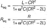
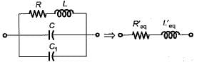
At high and medium frequencies, a resistor can be represented as shown in figure below.
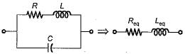
The equivalent impedance of the above shown resistor at an angular frequency ω rad/s is
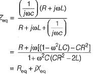
If the resistance is to remain independent of frequency i.e. to have the same value of resistance at medium frequencies as with d.c, we have:
CR2 = 2 L
so that, Req = R
The equivalent impedance of the above shown resistor at an angular frequency ω rad/s is
If the resistance is to remain independent of frequency i.e. to have the same value of resistance at medium frequencies as with d.c, we have:
CR2 = 2 L
so that, Req = R
A simple bridge circuit consists of a network of __________- a)3 resistance arms
- b)2 resistance arms
- c)4 resistance arms
- d)6 resistance arms
Correct answer is option 'C'. Can you explain this answer?
A simple bridge circuit consists of a network of __________
a)
3 resistance arms
b)
2 resistance arms
c)
4 resistance arms
d)
6 resistance arms
| | Alok Verma answered |
Introduction:
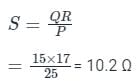
A simple bridge circuit is a network of resistors arranged in a bridge configuration. The bridge circuit is commonly used in electrical engineering for measuring resistance or as a null detector in sensor applications.
Components of a simple bridge circuit:
- 4 resistance arms: The bridge circuit consists of four resistors arranged in a diamond-shaped configuration. These resistors form the arms of the bridge circuit.
- Power source: The bridge circuit is typically powered by a voltage source, which provides the necessary electrical energy for the circuit to function.
- Output measurement: The output of the bridge circuit is taken across the two opposite corners of the diamond configuration. This output can be used to measure resistance or detect null points in the circuit.
Functionality of the bridge circuit:
- The bridge circuit operates on the principle of balancing the resistances in the network to achieve a null point or zero output voltage.
- By adjusting the values of the resistors in the bridge circuit, it is possible to measure unknown resistances or detect changes in resistance values.
Advantages of a simple bridge circuit:
- The bridge circuit is a versatile tool for measuring resistance accurately.
- It provides a high degree of sensitivity and precision in resistance measurements.
- The bridge circuit can be easily adapted for use in various applications by adjusting the resistor values.
In conclusion, a simple bridge circuit consists of 4 resistance arms arranged in a diamond shape. This configuration allows for accurate measurement of resistance values and null detection in electrical circuits.
In order to reduce skin effect in resistance standards when they are used on high frequency a.c.- a)adjacent turns of the resistance coil should carry current in the opposite direction
- b)they should be provided with four terminals
- c)the diameter of the resistance wire should be small
- d)none of the above
Correct answer is option 'C'. Can you explain this answer?
In order to reduce skin effect in resistance standards when they are used on high frequency a.c.
a)
adjacent turns of the resistance coil should carry current in the opposite direction
b)
they should be provided with four terminals
c)
the diameter of the resistance wire should be small
d)
none of the above
| | Saumya Basak answered |
- To reduce the error in standard resistance due to stray inductance, the adjacent wires should carry current in opposite direction so as to reduce the resultant magnetic field.
- To reduce the error due to contact (lead) resistance, a four terminal construction is used.
- To reduce the skin effect when used at high frequency a.c., small diameter wires are used.
Which is the most popular method for measuring low resistance?- a)ammeter-voltmeter method
- b)potentiometer method
- c)kelvin double bridge method
- d)ducter ohmmeter method
Correct answer is option 'C'. Can you explain this answer?
Which is the most popular method for measuring low resistance?
a)
ammeter-voltmeter method
b)
potentiometer method
c)
kelvin double bridge method
d)
ducter ohmmeter method
| | Pooja Patel answered |
Kelvin’s double bridge is used for the measurement of low resistances of the order of 1ῼ or less. Ammeter voltmeter method is used for the measurement of current flowing through and the voltage across the circuit.
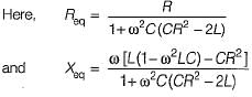
Find the unknown resistance value in a given circuit, given the bridge is balanced.
- a)10.2 Ω
- b)11.7 Ω
- c)10.5 Ω
- d)11.5 Ω
Correct answer is option 'A'. Can you explain this answer?
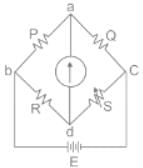
Find the unknown resistance value in a given circuit, given the bridge is balanced.
a)
10.2 Ω
b)
11.7 Ω
c)
10.5 Ω
d)
11.5 Ω
 | Cstoppers Instructors answered |
Concept:
- A Wheatstone bridge is a special arrangement of 4 resistors. It can be used to find an unknown resistance.
- If the Wheatstone bridge is balanced, there will be no current flowing through the galvanometer.
- Wheatstone bridge is used to measure the resistance with the help of a comparison method.
- The Wheatstone bridge work on the principle of null deflection.
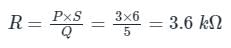
The bridge is balanced when: P/R = Q/S
Calculation:
Given that,
For a whetstone network, we have four resistance P, Q, R, and S, and their values are
P = 25 Ω
Q = 15 Ω
R = 17 Ω
S = ?
Balanced bridge: The bridge is said to be balanced when deflection in the galvanometer is zero i.e. no current flows through the galvanometer.
In the balanced condition P/R = Q/S, on mutually changing the position of cell and galvanometer, this condition will not change.
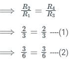
In case of the Wheatstone bridge shown in the below circuit diagram P = 3 kΩ and Q = 5 kΩ. The null value for the galvanometer is obtained when S = 6 kΩ. Find the value of R and the resistance measurement range of the bridge if ‘S’ value varies from 1 kΩ to 8 kΩ
- a)R = 2.6 kΩS = 500 Ω to 3.8 kΩ
- b)R = 5.6 kΩS = 400 Ω to 5.8 kΩ
- c)R = 3.6 kΩS = 500 Ω to 5.8 kΩ
- d)R = 3.6 kΩS = 600 Ω to 4.8 kΩ
Correct answer is option 'D'. Can you explain this answer?
In case of the Wheatstone bridge shown in the below circuit diagram P = 3 kΩ and Q = 5 kΩ. The null value for the galvanometer is obtained when S = 6 kΩ. Find the value of R and the resistance measurement range of the bridge if ‘S’ value varies from 1 kΩ to 8 kΩ
a)
R = 2.6 kΩ
S = 500 Ω to 3.8 kΩ
b)
R = 5.6 kΩ
S = 400 Ω to 5.8 kΩ
c)
R = 3.6 kΩ
S = 500 Ω to 5.8 kΩ
d)
R = 3.6 kΩ
S = 600 Ω to 4.8 kΩ
| | Pooja Patel answered |
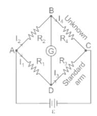
Concept
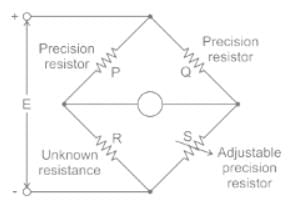
Wheatstone bridge:
It is an arrangement of four resistance which can be used to measure one of them in terms of rest. Here arms AB and BC are called ratio arm and arms AC and BD are called conjugate arms.
Where R is unknown resistance & S is standard resistance.
The bridge is said to be balanced when deflection in the galvanometer is zero i.e. no current flows through the galvanometer or in other words VB = VD.
In the balanced condition
P/Q = S/R
Explanation:
We know that the balanced condition of a bridge
P × S = R × Q
Now take minimum value of S = 1 kΩ

Now take the maximum value of S = 8 kΩ
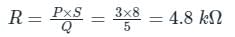
∴ Range of bridge = 600 Ω to 4.8 kΩ
In loss of charge method _______ is connected in parallel with the insulation _______ under test.- a)Capacitor, Resistance
- b)Inductor, Resistance
- c)Inductor, Capacitor
- d)None of the above
Correct answer is option 'A'. Can you explain this answer?
In loss of charge method _______ is connected in parallel with the insulation _______ under test.
a)
Capacitor, Resistance
b)
Inductor, Resistance
c)
Inductor, Capacitor
d)
None of the above
| | Gate Gurus answered |
Loss of Charge Method
In the loss of charge method, a known capacitor is connected in parallel with the insulation resistance under test and an electrostatic voltmeter as shown in Figure. The capacitor is charged to a suitable voltage through a battery by throwing the switch SW to contact 1 and is then allowed to discharge through the insulation resistance under test by throwing the switch SW to contact 2. The terminal voltage across the capacitor is noted during the discharging of the capacitor over a considerable period of time.
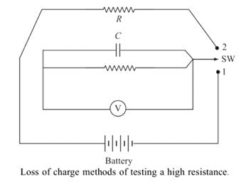
The voltage across parallel combinations is measured using an electrostatic voltmeter. If the value of resistance R is very large, then capacitor C requires more time for discharging. In such cases, the process becomes time-consuming. This method can be used effectively for the measurement of high resistances, but it needs a capacitor with a high leakage resistance.
The voltage across parallel combinations is measured using an electrostatic voltmeter. If the value of resistance R is very large, then capacitor C requires more time for discharging. In such cases, the process becomes time-consuming. This method can be used effectively for the measurement of high resistances, but it needs a capacitor with a high leakage resistance.
Which among the following is not a method for measurement of High Resistance?- a)Direct deflection method
- b)Direct charge method
- c)Loss of charge method
- d)Megaohm bridge Method
Correct answer is option 'B'. Can you explain this answer?
Which among the following is not a method for measurement of High Resistance?
a)
Direct deflection method
b)
Direct charge method
c)
Loss of charge method
d)
Megaohm bridge Method
| | Gate Gurus answered |
Methods used for measuring high resistance are:
- Loss of charge method
- Megger method
- Mega ohm bridge method
- Direct deflection method
In a megger, controlling torque is provided by- a)spring
- b)gravity
- c)coil
- d)eddy current
Correct answer is option 'C'. Can you explain this answer?
In a megger, controlling torque is provided by
a)
spring
b)
gravity
c)
coil
d)
eddy current
| | Mansi Choudhury answered |
Controlling Torque in a Megger
The correct answer to the question is option C, which states that controlling torque in a megger is provided by a coil. In this explanation, we will discuss the role of the coil in controlling torque in a megger.
1. Introduction to Megger:
A megger is a commonly used electrical testing instrument that is used to measure the insulation resistance of electrical equipment and circuits. It operates on the principle of applying a high voltage to the equipment under test and measuring the resulting current flow. The insulation resistance is then calculated using Ohm's law.
2. Torque Control in a Megger:
Torque control is an important aspect of a megger, as it determines the accuracy and reliability of the test results. The torque applied to the rotating parts of a megger must be carefully controlled to ensure consistent and repeatable measurements.
3. Role of the Coil:
The coil in a megger plays a crucial role in controlling the torque. It is a part of the torque control mechanism, and its function is to provide a counterbalancing force to the torque produced by the rotation of the instrument's rotor.
4. Working Principle:
When the megger is in operation, the rotor rotates due to the application of a high voltage. As the rotor rotates, it generates a torque that tends to rotate the instrument further. This torque needs to be counteracted to prevent excessive rotation and ensure accurate measurements.
5. Coil Design:
The coil in a megger is designed in a way that it produces a magnetic field when a current passes through it. This magnetic field interacts with the magnetic field generated by the rotor, creating a force that opposes the rotation. By controlling the current passing through the coil, the torque can be controlled effectively.
6. Current Control:
To control the torque, the current passing through the coil is adjusted based on the desired torque level. By increasing or decreasing the current, the counterbalancing force exerted by the coil can be adjusted accordingly.
7. Importance of Torque Control:
Accurate torque control is important in a megger to ensure that the rotating parts do not experience excessive wear and tear. It also helps in maintaining the accuracy and reliability of the test results by preventing unnecessary variations in the measurements.
In conclusion, the coil in a megger plays a vital role in controlling the torque. By producing a counterbalancing force, it helps in maintaining the accuracy and reliability of the insulation resistance measurements.
For the measurement of high resistances following methods are used:1. Loss of Charge Method2. Direct Deflection Method3. Substitution MethodWhich of the following is/are correct?- a)1 and 2
- b)2 and 3
- c)Only 1
- d)1 and 3
Correct answer is option 'A'. Can you explain this answer?
For the measurement of high resistances following methods are used:
1. Loss of Charge Method
2. Direct Deflection Method
3. Substitution Method
Which of the following is/are correct?
a)
1 and 2
b)
2 and 3
c)
Only 1
d)
1 and 3
| | Pooja Patel answered |
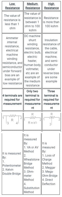
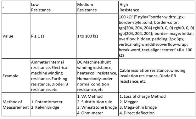
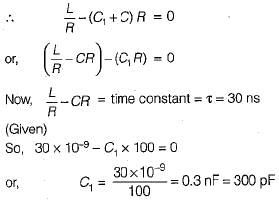
The Measurement of Resistance according to classification is shown below:
Consider the following in context of creeping in energy meter and identify the correct option.P: The primary reason of creeping is under-compensation for friction.Q: Creeping may be because of excessive voltage and vibrations.- a)P and Q both are correct
- b)P is correct, Q is incorrect
- c)P is incorrect, Q is correct
- d)P and Q both are incorrect
Correct answer is option 'C'. Can you explain this answer?
Consider the following in context of creeping in energy meter and identify the correct option.
P: The primary reason of creeping is under-compensation for friction.
Q: Creeping may be because of excessive voltage and vibrations.
a)
P and Q both are correct
b)
P is correct, Q is incorrect
c)
P is incorrect, Q is correct
d)
P and Q both are incorrect
| | Pooja Patel answered |
- Creeping in energy meters is a phenomenon due to which the Almunium disc rotates due to only voltage applied to the pressure coil and no current flows in the current coil
- The necessary condition for creeping is that the Pressure coil (PC) must be energized
- Creeping increases the speed of the disc under low load conditions which increases the meter reading
- The primary reason for creeping is over-compensation for friction
- Generally, the friction compensation is so adjusted to give a diving torque required to compensate for the starting friction of the disc
- Another cause of creeping is the excess voltage, vibrations, and stray magnetic fields across the PC.
- This develops the excessive friction compensating torque at low load and the disc rotates
Hence we could observe that
Statement P is incorrect, and statement Q is correct
A resistor R has an effective inductance of L and a distributed capacitance of C. its time constant at medium frequencies is- a)L/R - CR
- b)L/R
- c)CR
- d)CR - L/R
Correct answer is option 'A'. Can you explain this answer?
A resistor R has an effective inductance of L and a distributed capacitance of C. its time constant at medium frequencies is
a)
L/R - CR
b)
L/R
c)
CR
d)
CR - L/R
| | Debanshi Nair answered |
At medium frequencies, we have:
∴ Time constant,
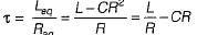
∴ Time constant,
Consider the following statements about the bridge measurement:
1. The measurement accuracy is directly related to the accuracy of the bridge component as well as that of the null indicator used.
2. The basic dc bridge used for accurate measurement of resistance is called Wheatstone’s bridge.
3. When the bridge is in balanced condition, current flows through the galvanometer, causing a deflection of its pointer.
4. A more sensitive galvanometer deflects by a greater amount for the same current.
5. The sensitivity of the bridge measurement can only be expressed in mm/μA.
Which of these statements is/are correct?- a)2 only
- b)1,3, 4 and 5
- c)2 and 4
- d)1 , 2 and 5
Correct answer is option 'C'. Can you explain this answer?
Consider the following statements about the bridge measurement:
1. The measurement accuracy is directly related to the accuracy of the bridge component as well as that of the null indicator used.
2. The basic dc bridge used for accurate measurement of resistance is called Wheatstone’s bridge.
3. When the bridge is in balanced condition, current flows through the galvanometer, causing a deflection of its pointer.
4. A more sensitive galvanometer deflects by a greater amount for the same current.
5. The sensitivity of the bridge measurement can only be expressed in mm/μA.
Which of these statements is/are correct?
a)
2 only
b)
1,3, 4 and 5
c)
2 and 4
d)
1 , 2 and 5
| | Mansi Datta answered |
- The measurement accuracy is directly related to the accuracy of the bridge component and not to that of the null indicator used.
- When the bridge is in balanced condition, no current flows through the galvanometer.
- The sensitivity of the bridge measurement can be expressed in mm/μA or degree/mA or radians/mA.
Which is the Important Part of megger?- a)Ohm Meter
- b)D.C. Generator
- c)Both of the above
- d)None of the above
Correct answer is option 'C'. Can you explain this answer?
Which is the Important Part of megger?
a)
Ohm Meter
b)
D.C. Generator
c)
Both of the above
d)
None of the above
| | Poulomi Ahuja answered |
Important Part of Megger
The important part of a megger consists of both an ohm meter and a D.C. generator.
1. Ohm Meter:
The ohm meter is an integral part of a megger and is used to measure electrical resistance. It is designed to measure the resistance of various electrical components and circuits. In the case of a megger, the ohm meter is used to measure the insulation resistance of cables, wires, and other electrical equipment. This is important because it helps to assess the quality of insulation and identify any potential faults or weaknesses that may compromise the safety and performance of the electrical system.
2. D.C. Generator:
The D.C. generator is another essential component of a megger. It generates a controlled and stable direct current (D.C.) voltage that is used to perform insulation resistance tests. The generator provides a high voltage output, typically in the range of 500 to 5000 volts, which is applied to the insulation being tested. This voltage is necessary to stress the insulation and detect any leakage currents or faults that may exist. The D.C. generator in a megger ensures that a reliable and consistent voltage is applied during the insulation resistance measurement.
3. Importance of Both Components:
Both the ohm meter and D.C. generator are crucial in a megger because they work together to assess the insulation resistance of electrical systems. The ohm meter measures the resistance, while the D.C. generator provides the voltage necessary for the test. By combining these two components, a megger can accurately measure the insulation resistance and identify any potential issues such as insulation breakdown, moisture ingress, or aging of the insulation material.
4. Benefits:
Having both an ohm meter and a D.C. generator in a megger offers several benefits:
- Accurate Measurement: The combination of the ohm meter and D.C. generator ensures accurate measurement of insulation resistance, enabling reliable assessment of the insulation quality.
- Versatility: The megger can be used for a wide range of applications, including testing insulation in cables, transformers, motors, generators, and other electrical equipment.
- Safety: Insulation resistance testing helps to ensure the safety of electrical systems by identifying any potential faults or weaknesses that may lead to electrical breakdown or hazards.
In conclusion, both the ohm meter and D.C. generator are important components of a megger. The ohm meter measures the resistance, while the D.C. generator provides the necessary voltage for insulation resistance testing. Their combination enables accurate measurement and assessment of insulation quality, ensuring the safety and reliability of electrical systems.
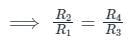
Each of the ratio arms of a laboratory type Wheatstone bridge has guaranteed accuracy of ±0.05%, while the standard arm has a guaranteed accuracy of ±0.1 %. The ratio arms are both set at 1 kΩ and and bridge is balanced with standard arm adjusted to 3154 Ω. The upper and the lower limits of the unknown resistance, based upon the guaranteed accuracies of the known bridge arms are respectively- a)3217 Ω and 3091 Ω
- b)3160.3 Ω and 3091.7 Ω
- c)3160.3 Ω and 3091 Ω
- d)3160.3 Ω and 3147.7 Ω
Correct answer is option 'D'. Can you explain this answer?
Each of the ratio arms of a laboratory type Wheatstone bridge has guaranteed accuracy of ±0.05%, while the standard arm has a guaranteed accuracy of ±0.1 %. The ratio arms are both set at 1 kΩ and and bridge is balanced with standard arm adjusted to 3154 Ω. The upper and the lower limits of the unknown resistance, based upon the guaranteed accuracies of the known bridge arms are respectively
a)
3217 Ω and 3091 Ω
b)
3160.3 Ω and 3091.7 Ω
c)
3160.3 Ω and 3091 Ω
d)
3160.3 Ω and 3147.7 Ω
| | Sahil Datta answered |
Value of unknown resistance,
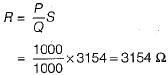
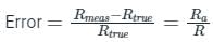
Now, percentage error in determination of R is
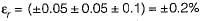
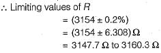
Now, percentage error in determination of R is
In measuring resistance by voltmeter-ammeter method, the voltmeter can be connected either across supply or across the resistance. If the resistance is low, the voltmeter should be connected- a)across the supply
- b)across the resistance
- c)either across the supply or across the resistance
- d)neither across the supply nor across the resistance
Correct answer is option 'B'. Can you explain this answer?
In measuring resistance by voltmeter-ammeter method, the voltmeter can be connected either across supply or across the resistance. If the resistance is low, the voltmeter should be connected
a)
across the supply
b)
across the resistance
c)
either across the supply or across the resistance
d)
neither across the supply nor across the resistance
| | Pooja Patel answered |
V–A Method:
In this method, the voltmeter is connected across the supply.
V = Voltmeter reading
A = Ammeter reading
VL = Voltage across load R.
IL = Current flowing through load R.
R = Unknown resistance to be measured
Ra = Internal resistance of the ammeter
Va= voltage drop across ammeter.
V = VL + Va
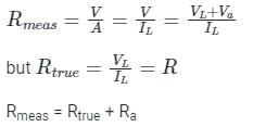
So, in this method measured value is greater than the true value. This error is due to an ammeter.
The error is high for very low values of unknown resistance R.
So, in this method measured value is greater than the true value. This error is due to an ammeter.
The error is high for very low values of unknown resistance R.
A–V Method:
In this method, the voltmeter is connected across the resistance.
V = Voltmeter reading
A = Ammeter reading
VL = Voltage across load R.
R = Unknown resistance to be measured
IL = Current flowing through load R.
IV = Current flowing through the voltmeter.
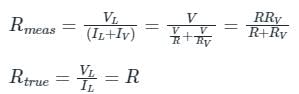
The measured value is less than the true value. In this method, the error is due to the voltmeter.
The error is low for very low values of unknown resistance R.
The measured value is less than the true value. In this method, the error is due to the voltmeter.
The error is low for very low values of unknown resistance R.
Observations:
- In both methods errors due to load side instruments.
- V – A method is best suitable for high resistances in the medium range.
- A – V method is best suitable for low resistances in the medium range.
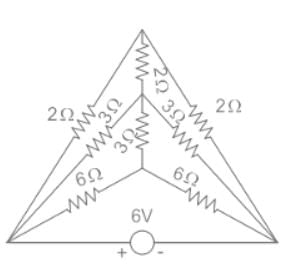
Find the value of source current (I) from the circuit as shown below
- a)1 A
- b)2 A
- c)3 A
- d)4 A
Correct answer is option 'C'. Can you explain this answer?
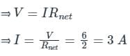
Find the value of source current (I) from the circuit as shown below
a)
1 A
b)
2 A
c)
3 A
d)
4 A
| | Pioneer Academy answered |
Concept:
Wheatstone Bridge:
- The Wheatstone Bridge has four resistors R1, R2, R3, and R4.
- A Voltage source is connected across one pair of diagonally opposite points A and C. This is called the battery arm.
- Between the other two vertices, B and D, a galvanometer G is connected. This is called the Galvanometer arm.
- For the sake of simplicity, let us assume that the cell has no internal resistance.
Balanced Bridge:
- The resistors are arranged in such a manner that the current through the galvanometer is zero, i.e. Ig = 0.
- The bridge is said to be balanced when deflection in the galvanometer is zero i.e. no current flows through the galvanometer or in other words VB = VD.
- Under the balanced condition,
- The above equation relates the four resistors is called the balance condition of the Wheatstone Bridge for which the galvanometer will show zero or null deflection.
Explanation:
According to the question given below:

- In the above figure, there are two sets of Balanced Wheatstone bridges.
- We know the condition for a balanced Wheatstone bridge is
- The condition holds true for both the equations mentioned above, therefore, the current in the 2 Ω and 3 Ω is zero.
- We can replace 2 Ω and 3 Ω from the circuit with an open circuit.
- The resistances of the top horizontal line are in series (Ignoring the 2 Ω branch, since no current passes through it).
⇒ Rtop = 2 Ω + 2 Ω = 4 Ω
- The resistances of the middle horizontal line are in series (Ignoring the 3 Ω resistance branch, since no current passes through it).
⇒ Rmidddle = 3 Ω + 3 Ω = 6Ω
- The resistances in the bottom horizontal line are in series.
⇒ Rbottom = 6 Ω + 6 Ω = 12 Ω
- The net resistance is (considering Rtop, Rmiddle, and Rbottom).
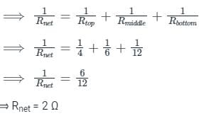
- The current through the battery (I) could be obtained by Ohm's Law,
The direct deflection method uses the principle of- a)Ammeter-Galvanometer Method
- b)Ammeter-Voltmeter Method
- c)Shunt-capacitor method
- d)Null Method
Correct answer is option 'B'. Can you explain this answer?
The direct deflection method uses the principle of
a)
Ammeter-Galvanometer Method
b)
Ammeter-Voltmeter Method
c)
Shunt-capacitor method
d)
Null Method
| | Pooja Patel answered |
This method basically uses the principle of the ammeter-voltmeter method. The microammeter is replaced by a highly sensitive galvanometer.
A shunt is included in the circuit for the protection of the galvanometer and also to provide several ranges. The deflection of the galvanometer indicates the value of the insulation resistance under test.
A test-short switch is connected to the circuit so that when a specimen having capacitance such as a length of a cable, is tested by this method, it can be discharged easily after the measurement.
Which of the following method is used for removing the leakage current from bridges?- a)Direct deflection method
- b)Loss of charge method
- c)Mega Ohm bridge method
- d)None of the above
Correct answer is option 'C'. Can you explain this answer?
Which of the following method is used for removing the leakage current from bridges?
a)
Direct deflection method
b)
Loss of charge method
c)
Mega Ohm bridge method
d)
None of the above
| | Ankita Das answered |
The correct answer is option 'C' - Direct deflection method.
Explanation:
Bridges are electronic circuits used to measure unknown electrical quantities. However, bridges are prone to leakage current, which can affect the accuracy of the measurements. Leakage current refers to the small current that flows through unintended paths in the bridge circuit. To ensure accurate measurements, it is necessary to remove or minimize this leakage current.
The direct deflection method is a technique used to remove the leakage current from bridges. It involves the use of a sensitive galvanometer or a null detector to detect the presence of leakage current. The galvanometer is connected in parallel to the bridge circuit, and its deflection is observed.
Here is a detailed explanation of the direct deflection method:
1. Set up the bridge circuit: The bridge circuit is set up according to the requirements of the measurement. It typically consists of resistors, capacitors, and/or inductors.
2. Connect the galvanometer: The galvanometer is connected in parallel to the bridge circuit. It is important to ensure that the galvanometer is sensitive enough to detect small currents.
3. Adjust the bridge: The bridge is adjusted by varying the values of the components until the galvanometer shows no deflection. This indicates that the bridge is balanced, and there is no leakage current flowing through the circuit.
4. Measure the unknown quantity: Once the bridge is balanced, the unknown quantity can be measured accurately. The value of the unknown quantity can be determined from the known values of the other components in the bridge circuit.
Advantages of the direct deflection method:
- It is a simple and effective technique for removing leakage current.
- It allows for accurate measurements of unknown electrical quantities.
- It does not require complex calculations or additional equipment.
In conclusion, the direct deflection method is used to remove leakage current from bridges. By connecting a sensitive galvanometer in parallel to the bridge circuit and adjusting the bridge until the galvanometer shows no deflection, accurate measurements of unknown quantities can be obtained.
A cable is tested by loss of charge method using a ballistic galvanometer with following results:
Discharged immediately after electrification, deflection 200 divisions.
Discharged after 20s and after electrification:
(i) deflection, 100 divisions,
(ii) when in parallel with a resistance of 10 MW, deflection 50 divisions.
What is the insulation resistance of the cable? - a)20 MΩ
- b)30 MΩ
- c)40 MΩ
- d)10 MΩ
Correct answer is option 'D'. Can you explain this answer?
A cable is tested by loss of charge method using a ballistic galvanometer with following results:
Discharged immediately after electrification, deflection 200 divisions.
Discharged after 20s and after electrification:
(i) deflection, 100 divisions,
(ii) when in parallel with a resistance of 10 MW, deflection 50 divisions.
What is the insulation resistance of the cable?
Discharged immediately after electrification, deflection 200 divisions.
Discharged after 20s and after electrification:
(i) deflection, 100 divisions,
(ii) when in parallel with a resistance of 10 MW, deflection 50 divisions.
What is the insulation resistance of the cable?
a)
20 MΩ
b)
30 MΩ
c)
40 MΩ
d)
10 MΩ
| | Tanishq Chauhan answered |
Let R be the insulation resistance of the cable and R' be the equivalent resistance of the parallel combination of insulation resistance R and 10 MΩ resistance.
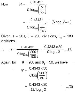
Dividing equation (1) by (2), we get:
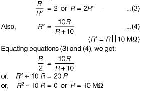
Dividing equation (1) by (2), we get:
Low resistance refers to _________- a)resistances of the order of 1ῼ
- b)resistances of the order of 1kῼ
- c)resistances of the order of 1mῼ
- d)resistances of the order of 1Mῼ
Correct answer is option 'A'. Can you explain this answer?
Low resistance refers to _________
a)
resistances of the order of 1ῼ
b)
resistances of the order of 1kῼ
c)
resistances of the order of 1mῼ
d)
resistances of the order of 1Mῼ
| | Pooja Patel answered |
Low resistance refers to resistance of the order of 1ῼ or less than that. Medium resistances range from above 1ῼ to a few kῼ. Any resistance value greater than a few kῼ is known as high resistance.
Which among the following is a method of absolute measurement of resistance?- a)Voltmeter ammeter method
- b)Wheatstone bridge method
- c)Lorentz method
- d)None of the above
Correct answer is option 'C'. Can you explain this answer?
Which among the following is a method of absolute measurement of resistance?
a)
Voltmeter ammeter method
b)
Wheatstone bridge method
c)
Lorentz method
d)
None of the above
| | Pooja Patel answered |
- There are many methods by which resistance can be measured absolutely in the electromagnetic system of units
- The first absolute measurements of resistance were made by Kirchhoff in 1849
- Weber proposed three methods by which the resistance of a wire can be determined absolutely
- The absolute measurement of resistance is done by Lorentz method
Which of the following is/are drawbacks of the loss of charge method?- a)Current doesn’t depend on the insulation resistance
- b)Insulation resistance depends to a greater extent on the application of the voltage.
- c)Effect of temperature on insulating material
- d)All of the above
Correct answer is option 'D'. Can you explain this answer?
Which of the following is/are drawbacks of the loss of charge method?
a)
Current doesn’t depend on the insulation resistance
b)
Insulation resistance depends to a greater extent on the application of the voltage.
c)
Effect of temperature on insulating material
d)
All of the above
| | Gate Gurus answered |
The loss of charge method has certain serious drawbacks and these are as follows:
(i) The current actually flowing, does not depend upon the insulation resistance alone. Due to the absorption effect in the dielectric of the capacitor, a small absorption current also flows through the insulation. This absorption current decays very rapidly at first but afterwards, this decay is very slow, therefore, observations must be continued for a longer period in order to attain high accuracy in measurement.
(ii) In the rubber-covered cables this absorption current is large, about 5-6 times the leakage current and is dependant only on the resistance after the application of the input voltage for 1 min and is equal in value to the true leakage current even after 7 min. It has been observed that the absorption current is about 5% to 10% of the total current flowing through the insulation after the voltage has been applied for 6 to 7 hours. Therefore, the insulation resistance depends to a greater extent on the time interval of application of the voltage. In commercial testing, the time of application of the voltage is normally not more than 1-2 min and therefore, from the foregoing discussion it is clear that the insulation resistance so obtained will be much less than the actual value.
(iii) The resistance of the insulating materials decreases with the increasing temperature and in some materials, this drop is very rapid. Therefore, it is important that while stating the results of insulation resistance measurements, the temperature must be specified at which the measurements have been carried out.
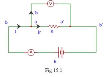
In the following figure, what is the value of I?
- a)I = IV + Ir
- b)I = IV – Ir
- c)I = IV Ir
- d)I = IV ⁄ Ir
Correct answer is option 'A'. Can you explain this answer?
In the following figure, what is the value of I?
a)
I = IV + Ir
b)
I = IV – Ir
c)
I = IV Ir
d)
I = IV ⁄ Ir
| | Pooja Patel answered |
By applying Kirchhoff’s current law at the node N from fig we get,
I = IV + Ir
where,
I is the total series current flowing through the circuit
Iv is the current flowing through the voltmeter
Ir is the current flowing through the resistance R.
I = IV + Ir
where,
I is the total series current flowing through the circuit
Iv is the current flowing through the voltmeter
Ir is the current flowing through the resistance R.
How is the voltage drop across a low resistance related to lead resistance?- a)it contains contact resistance
- b)it depends on the magnitude of voltage drop
- c)it depends on the type of null detector used
- d)it does not contain any contact resistance
Correct answer is option 'D'. Can you explain this answer?
How is the voltage drop across a low resistance related to lead resistance?
a)
it contains contact resistance
b)
it depends on the magnitude of voltage drop
c)
it depends on the type of null detector used
d)
it does not contain any contact resistance
| | Pooja Patel answered |
The voltage drop measured across a low resistance does not contain any contact and lead resistances of the components and is independent of it.
The resistances of the four arms of a Wheatstone bridge are as follows: AB = 100, BC = 10, CD = 4, DA = 50 ohms. A 20-ohm resistance galvanometer is connected between BD. If there is a potential difference of 10 V across the AC, then find the value of the current flowing through the galvanometer.- a)0.05 A
- b)0.5 A
- c)5.1 mA
- d)5 A
Correct answer is option 'C'. Can you explain this answer?
The resistances of the four arms of a Wheatstone bridge are as follows: AB = 100, BC = 10, CD = 4, DA = 50 ohms. A 20-ohm resistance galvanometer is connected between BD. If there is a potential difference of 10 V across the AC, then find the value of the current flowing through the galvanometer.
a)
0.05 A
b)
0.5 A
c)
5.1 mA
d)
5 A
| | Pooja Patel answered |
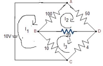
Applying KVL in loop 1:
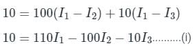
Applying KVL in loop 2:
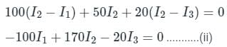
Applying KVL in loop 3:
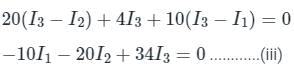
Solving equations (i), (ii), and (iii), we get:
I1 = 0.276 A
I2 = 0.184 A
I3 = 0.189 A
The current through the galvanometer is:
I = 0.189 - 0.184
I = 0.005 A = 5 mA
The operation of a Megger is based on which of the following?- a)Dynamometer
- b)Electrostatic meter
- c)Moving coil meter
- d)Moving iron meter
Correct answer is option 'C'. Can you explain this answer?
The operation of a Megger is based on which of the following?
a)
Dynamometer
b)
Electrostatic meter
c)
Moving coil meter
d)
Moving iron meter
| | Pooja Patel answered |
- Megger is a portable instrument to measure high insulation resistances
- It basically works on the principle of electromagnetic induction
- The electrical power to a megger is provided by permanent magnet D.C. generator
- The test voltages are usually of order 500, 1000, or 2500 V are generated by a hand-driven generator (permanent magnet D.C. generator)
- The operation of a megger is based on moving coil meter
A 100 Ω resistor has a time constant of 30 ns. What is the value of capacitor to be connected in parallel with the resistor to make its phase angle equal to zero?- a)30 pF
- b)300 nF
- c)30 nF
- d)300 pF
Correct answer is option 'D'. Can you explain this answer?
A 100 Ω resistor has a time constant of 30 ns. What is the value of capacitor to be connected in parallel with the resistor to make its phase angle equal to zero?
a)
30 pF
b)
300 nF
c)
30 nF
d)
300 pF
| | Mayank Sengupta answered |
Let the the required capacitance be C1.
Without the external capacitance C1,
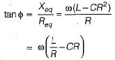
Now, when an external capacitance C1 is connected in parallel, then new phase angle
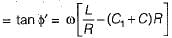
For the phase angle to be zero, tan φ = 0
Without the external capacitance C1,
Now, when an external capacitance C1 is connected in parallel, then new phase angle
For the phase angle to be zero, tan φ = 0
Kelvin double bridge is best suited for the measurement of- a)Resistances of very low value
- b)Low value capacitance
- c)Resistances of very high value
- d)High value capacitance
Correct answer is option 'A'. Can you explain this answer?
Kelvin double bridge is best suited for the measurement of
a)
Resistances of very low value
b)
Low value capacitance
c)
Resistances of very high value
d)
High value capacitance
| | Pooja Patel answered |
Kelvin's double bridge is used for measuring low values of resistance.
Note:
What is the significance of measuring low resistances?- a)voltage drop across the circuit is high
- b)contact and lead resistances are appreciable
- c)there is no power loss
- d)no current flows through the bridge circuit
Correct answer is option 'B'. Can you explain this answer?
What is the significance of measuring low resistances?
a)
voltage drop across the circuit is high
b)
contact and lead resistances are appreciable
c)
there is no power loss
d)
no current flows through the bridge circuit
| | Pooja Patel answered |
When measuring low resistances of the order of 1 ῼ or even less, lead and contact resistances of the order of even 0.002 ῼ cannot be neglected. High currents flow through low resistance circuits.
A megger is a device used for measuring:- a)Extremely high voltages
- b)Extremely high currents
- c)Extremely high resistances
- d)All of the above
Correct answer is option 'C'. Can you explain this answer?
A megger is a device used for measuring:
a)
Extremely high voltages
b)
Extremely high currents
c)
Extremely high resistances
d)
All of the above
| | Pooja Patel answered |
The Megger method is used for the measurement of the high value of resistance. And this is best suitable for the measurement of insulation resistance of cables.
Additional Information
To measure High resistance Three(3) terminals are required.
Where,
Terminals 1 and 2 are input terminals, Terminal 3 is called Guard Terminal
Guard Terminal is used to eliminate or bypass Leakage currents while measuring.
Examples of High Resistance Materials:
- Cable Insulation Resistance.
- All Motors, generators, and transformers winding's insulation resistance.
- All semiconductor devices when reverse biased.
Methods to measure High Resistance:
- Loss of charge method.
- Direct-Deflection method.
- Mega ohm Bridge.
- Meggar.
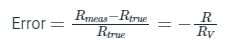
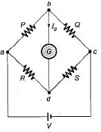
A highly sensitive galvanometer can detect a current as low as 0.1 nA. This galvanometer is used in a Wheatstone bridge as a detector as shown in figure below. The resistance of galvanometer is negligible.
Each arm of the bridge has a resistance of 1 kΩ and the input voltage applied to bridge is 20 V. Neglecting the resistance of the galvanometer as compared with the internal resistance of bridge, the smallest change in the resistance which can be detected is- a) 20 μΩ
- b)15 μΩ
- c)2 μΩ
- d)1 μΩ
Correct answer is option 'A'. Can you explain this answer?
A highly sensitive galvanometer can detect a current as low as 0.1 nA. This galvanometer is used in a Wheatstone bridge as a detector as shown in figure below. The resistance of galvanometer is negligible.
Each arm of the bridge has a resistance of 1 kΩ and the input voltage applied to bridge is 20 V. Neglecting the resistance of the galvanometer as compared with the internal resistance of bridge, the smallest change in the resistance which can be detected is
Each arm of the bridge has a resistance of 1 kΩ and the input voltage applied to bridge is 20 V. Neglecting the resistance of the galvanometer as compared with the internal resistance of bridge, the smallest change in the resistance which can be detected is
a)
20 μΩ
b)
15 μΩ
c)
2 μΩ
d)
1 μΩ
| | Rahul Chakraborty answered |
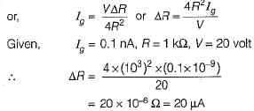
Let the resistance R be changed to R + ΔR.
The Thevenin's equivalent circuit across terminals bd is shown below.
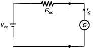
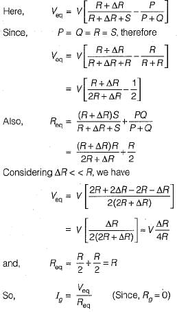
The Thevenin's equivalent circuit across terminals bd is shown below.
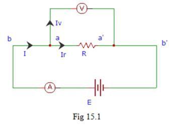
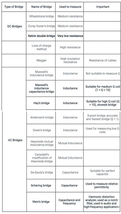
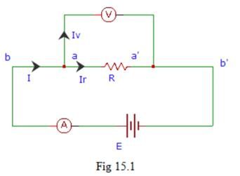
In fig 15.1, the terminals aa’ are used for _________
- a)measuring the current flow through the circuit
- b)measuring the power dissipation of the circuit
- c)measuring the resistance of the circuit
- d)measuring the voltage drop across the resistance
Correct answer is option 'D'. Can you explain this answer?
In fig 15.1, the terminals aa’ are used for _________
a)
measuring the current flow through the circuit
b)
measuring the power dissipation of the circuit
c)
measuring the resistance of the circuit
d)
measuring the voltage drop across the resistance
| | Pooja Patel answered |
The terminals aa’ are used for the measurement of the voltage drop across the resistance R. An voltmeter V is connected across the terminals aa’.
Which is not a source of error in the measurement of low resistance?- a)contact resistance drops at the leads
- b)thermal e.m.f
- c)temperature effect
- d)power dissipation through the circuit
Correct answer is option 'A'. Can you explain this answer?
Which is not a source of error in the measurement of low resistance?
a)
contact resistance drops at the leads
b)
thermal e.m.f
c)
temperature effect
d)
power dissipation through the circuit
| | Pooja Patel answered |
As the current flowing through a low resistance circuit is low, the voltage drop across the terminals due to contact and lead resistances is negligible. Thermal e.m.f occurs in a circuit when its temperature increases due to high current flow.
How is the contact resistance related to the circuit while measuring a low resistance?- a)independent of the type of resistance
- b)it is negligible
- c)depends on the e.m.f source
- d)it is very high
Correct answer is option 'B'. Can you explain this answer?
How is the contact resistance related to the circuit while measuring a low resistance?
a)
independent of the type of resistance
b)
it is negligible
c)
depends on the e.m.f source
d)
it is very high
| | Pooja Patel answered |
The contact and lead resistances form a part of the circuit whose resistance is very high. As a result the contact and lead resistances are usually neglected compared to the high resistance value.
Fig 15.1 represents?
- a)construction of medium resistance
- b)construction of high resistance
- c)construction of low resistance
- d)construction of very low resistance
Correct answer is option 'C'. Can you explain this answer?
Fig 15.1 represents?
a)
construction of medium resistance
b)
construction of high resistance
c)
construction of low resistance
d)
construction of very low resistance
| | Pooja Patel answered |
Fig 15.1, illustrates the construction of low resistance. A is an ammeter used to measure current through the circuit, while V is the voltmeter used to measure voltage.
The electrical power to a megger is provided by- a)Battery
- b)Permanent magnet D.C. generator
- c)AC generator
- d)Either AC or DC generator
Correct answer is option 'B'. Can you explain this answer?
The electrical power to a megger is provided by
a)
Battery
b)
Permanent magnet D.C. generator
c)
AC generator
d)
Either AC or DC generator
| | Pooja Patel answered |
- Megger is a portable instrument to measure high insulation resistances
- It basically works on the principle of electromagnetic induction
- The electrical power to a megger is provided by permanent magnet D.C. generator
- The test voltages are usually of order 500, 1000, or 2500 V are generated by hand driven generator (permanent magnet D.C. generator)
A megger is an instrument that gives the reading in:- a)volt
- b)ohm
- c)henry
- d)ampere
Correct answer is option 'B'. Can you explain this answer?
A megger is an instrument that gives the reading in:
a)
volt
b)
ohm
c)
henry
d)
ampere
| | Pooja Patel answered |
Megger:
- Megger is a portable instrument that is used to measure the insulation resistance of the electrical machinery or system.
- It can be battery operated or mechanically operated (hand crank dc generator) and gives a direct reading in ohms.
- It basically works on the principle of electromagnetic induction.
- The electrical power to a megger is provided by a permanent magnet D.C. generator.
- The operating voltage of a megger is about 50 to 100 V.
Points to remember:
- Megger is also called an insulation tester because it is used to measure the insulation resistance of underground cables, motor windings, etc.
- The loss of charge method also used to measure the insulation resistance in MΩ.
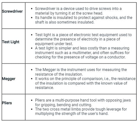
Which instrument is used for conducting tests after wire installation?- a)Screwdriver
- b)Test Light
- c)Megger
- d)Pliers
Correct answer is option 'C'. Can you explain this answer?
Which instrument is used for conducting tests after wire installation?
a)
Screwdriver
b)
Test Light
c)
Megger
d)
Pliers
| | Pooja Patel answered |
After completion of the wire installation, we do the following test:
(1) Polarity Test:
- In this test If the switch is inserted in the live line, the megger will indicate ‘zero’ reading.
- On the other hand, if the pointer of the megger shows ‘infinity’ or any high value of resistance, it may be concluded that the switch has not been inserted in the live wire; it has been placed in the neutral or some other wire
(2) To Test the Effectiveness of Earth resistance:
In megger, the arrangement is such that when the handle of the instrument is turned, alternating current flows through the earth, but direct current flows through the device for measuring the earth resistance.
As both of these tests is performed by using Megger only. So, megger is the correct option.
Note:
Assertion (A): Manganin is an alloy of copper, manganese and nickel and is universally used as resistance material for precision resistors and for resistance measuring apparatus,
Reason (R): The foremost property of manganin is that it has almost zero temperature coefficient of resistance near about room temperature. Moreover, it shows no ageing effect.- a)Both A and R are true and R is a correct explanation of A.
- b)Both A and R are true but R is not a correct explanation of A.
- c)A is true but R is false.
- d)A is false but R is true.
Correct answer is option 'A'. Can you explain this answer?
Assertion (A): Manganin is an alloy of copper, manganese and nickel and is universally used as resistance material for precision resistors and for resistance measuring apparatus,
Reason (R): The foremost property of manganin is that it has almost zero temperature coefficient of resistance near about room temperature. Moreover, it shows no ageing effect.
Reason (R): The foremost property of manganin is that it has almost zero temperature coefficient of resistance near about room temperature. Moreover, it shows no ageing effect.
a)
Both A and R are true and R is a correct explanation of A.
b)
Both A and R are true but R is not a correct explanation of A.
c)
A is true but R is false.
d)
A is false but R is true.
| | Shanaya Mehta answered |
Understanding the Assertion (A)
Manganin is indeed an alloy comprising copper, manganese, and nickel. This specific combination gives it unique properties that are highly valued in electrical applications.
Evaluating the Reason (R)
The reason provided states that manganin has an almost zero temperature coefficient of resistance and shows no aging effect.
Conclusion: Why Option A is Correct
Both the assertion and reason are true, and the reason correctly explains why manganin is preferred in precision applications. The properties of manganin, primarily its minimal temperature coefficient and stability over time, contribute significantly to its usage as a resistance material.
Thus, the correct answer is:
Option A: Both A and R are true and R is a correct explanation of A.
Manganin is indeed an alloy comprising copper, manganese, and nickel. This specific combination gives it unique properties that are highly valued in electrical applications.
- Manganin is widely recognized for its stability and reliability.
- It is predominantly used in precision resistors and resistance measuring instruments.
Evaluating the Reason (R)
The reason provided states that manganin has an almost zero temperature coefficient of resistance and shows no aging effect.
- Zero temperature coefficient of resistance means that the resistance of manganin remains almost constant with temperature changes, making it ideal for precision applications.
- The lack of aging effect implies that its resistive properties do not degrade over time, ensuring long-term accuracy.
Conclusion: Why Option A is Correct
Both the assertion and reason are true, and the reason correctly explains why manganin is preferred in precision applications. The properties of manganin, primarily its minimal temperature coefficient and stability over time, contribute significantly to its usage as a resistance material.
Thus, the correct answer is:
Option A: Both A and R are true and R is a correct explanation of A.
A resistance R is measured using the connections shown in figure below.
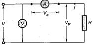
The current measured is 10 A on a range 10 A and the voltage measured is 125 V on a range of 150 V. The scale of the ammeter and voltmeter are uniform, the total scale divisions of ammeter are 100 and that of voltmeter are 150. The scales of these instruments are such that 1/10 of a scale can be distinguished. The constructional error of the ammeter is ±0.3% and that of voltmeter is ±0.4%. The resistance of ammeter is 0.25 Ω. The unknown resistance will be specified as:- a)R - 12.50 + 0.4%
- b)R = 12.25 + 0.867%
- c)R = 12.50 + 0.867%
- d)R = 12.25 + 0.467%
Correct answer is option 'B'. Can you explain this answer?
A resistance R is measured using the connections shown in figure below.
The current measured is 10 A on a range 10 A and the voltage measured is 125 V on a range of 150 V. The scale of the ammeter and voltmeter are uniform, the total scale divisions of ammeter are 100 and that of voltmeter are 150. The scales of these instruments are such that 1/10 of a scale can be distinguished. The constructional error of the ammeter is ±0.3% and that of voltmeter is ±0.4%. The resistance of ammeter is 0.25 Ω. The unknown resistance will be specified as:
The current measured is 10 A on a range 10 A and the voltage measured is 125 V on a range of 150 V. The scale of the ammeter and voltmeter are uniform, the total scale divisions of ammeter are 100 and that of voltmeter are 150. The scales of these instruments are such that 1/10 of a scale can be distinguished. The constructional error of the ammeter is ±0.3% and that of voltmeter is ±0.4%. The resistance of ammeter is 0.25 Ω. The unknown resistance will be specified as:
a)
R - 12.50 + 0.4%
b)
R = 12.25 + 0.867%
c)
R = 12.50 + 0.867%
d)
R = 12.25 + 0.467%
| | Rahul Chakraborty answered |
Reading error of voltmeter
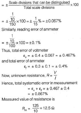
For the arrangement shown in given figure, ammeter is near to the unknown test resistance (R), therefore
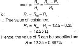
For the arrangement shown in given figure, ammeter is near to the unknown test resistance (R), therefore
Chapter doubts & questions for Measurement & Resistance - 6 Months Preparation for GATE Electrical 2026 is part of Electrical Engineering (EE) exam preparation. The chapters have been prepared according to the Electrical Engineering (EE) exam syllabus. The Chapter doubts & questions, notes, tests & MCQs are made for Electrical Engineering (EE) 2026 Exam. Find important definitions, questions, notes, meanings, examples, exercises, MCQs and online tests here.
Chapter doubts & questions of Measurement & Resistance - 6 Months Preparation for GATE Electrical in English & Hindi are available as part of Electrical Engineering (EE) exam. Download more important topics, notes, lectures and mock test series for Electrical Engineering (EE) Exam by signing up for free.
6 Months Preparation for GATE Electrical675 videos|1390 docs|885 tests |