


All Exams > Electrical Engineering (EE) > 6 Months Preparation for GATE Electrical > All Questions
All questions of Network Theory (Electric Circuits) for Electrical Engineering (EE) Exam
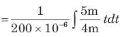
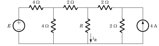
In the circuit of the fig the value of the voltage source E is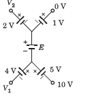
a)-16 Vb) 4 Vc)-6 Vd)16 VCorrect answer is 'A'. Can you explain this answer?
a)-16 V
b) 4 V
c)-6 V
d)16 V
Correct answer is 'A'. Can you explain this answer?
| | Shail Joshi answered |
Going from 10 V to 0 V
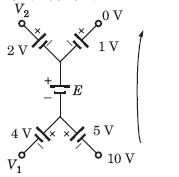
10+5+E+1 = 0

Req = ?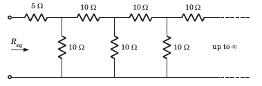
- a)11.86 Ω
- b)10 Ω
- c)25 Ω
- d)11.18 Ω
Correct answer is option 'D'. Can you explain this answer?
Req = ?
a)
11.86 Ω
b)
10 Ω
c)
25 Ω
d)
11.18 Ω
| | Sagar Joshi answered |
We infer from the given diagram that the same pattern is followed after every 10ohm resistor. The infinite pattern in parallel as a whole is considered as to be Rx.
Thus, Rx = R + (R||Rx)
Solving for Rx, we get Rx = 1.62R, where R=10ohm.
So we have Rx = (1.62ohm)*(10ohm), which gives Rx=16.2ohm
Therefore, Req = 5 + (10||16.2)
=> 5 + [(10*16.2)/(10+16.2)] => Req = 5 + (162/26.2) which gives Req=11.18 ohm.
Thus, Rx = R + (R||Rx)
Solving for Rx, we get Rx = 1.62R, where R=10ohm.
So we have Rx = (1.62ohm)*(10ohm), which gives Rx=16.2ohm
Therefore, Req = 5 + (10||16.2)
=> 5 + [(10*16.2)/(10+16.2)] => Req = 5 + (162/26.2) which gives Req=11.18 ohm.
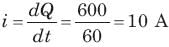
Can you explain the answer of this question below:The quantity of a charge that will be transferred by a current flow of 10 A over 1 hour period is_________ ?
- A:
10 C
- B:
3.6 x 10⁴ C
- C:
2.4 x 10³ C
- D:
1.6 x 10² C
The answer is b.
The quantity of a charge that will be transferred by a current flow of 10 A over 1 hour period is_________ ?
10 C
3.6 x 10⁴ C
2.4 x 10³ C
1.6 x 10² C
| | Aman Mehra answered |
We know that, I=Q/t or Q=I x t= 10x1 hours
{since unit of current is Cs-1, therefore time should be in seconds}
Therefore, Q=10x60x60=36000=3.6x10⁴ C
{since unit of current is Cs-1, therefore time should be in seconds}
Therefore, Q=10x60x60=36000=3.6x10⁴ C
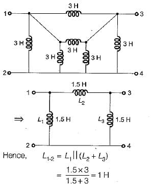
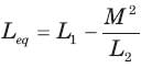
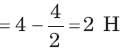
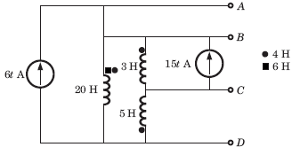
The equivalent inductance for the inductive circuit shown below at terminal “ 1 - 2 ” is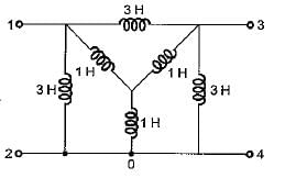
- a)1/4H
- b)1H
- c)3/4H
- d)1/2H
Correct answer is option 'B'. Can you explain this answer?
The equivalent inductance for the inductive circuit shown below at terminal “ 1 - 2 ” is
a)
1/4H
b)
1H
c)
3/4H
d)
1/2H
| | Sanaya Basu answered |
Converting the internal star connected inductance to an equivalent delta, the circuit reduces as shown below.

Hence, equivalent circuit becomes as shown below.
i = ?
- a)1 A
- b)2 A
- c)3 A
- d)4 A
Correct answer is option 'A'. Can you explain this answer?
i = ?
a)
1 A
b)
2 A
c)
3 A
d)
4 A
| | Stuti Datta answered |
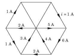
Based on kirchoffs current law, we know that incoming currents at a node is equals to outgoing currents.So based on this 4 and 3 will get canceled with 5 and 2 so,finally i=1.
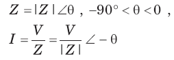
In a two element series circuit, the applied voltage and the resulting current are v(t) = 60 + 66sin (10 t) V, i(t)=2.3sin (103t + 68.3o) A.The nature of the elements would be- a)R-C
- b)L-C
- c)R-L
- d)R-R
Correct answer is option 'A'. Can you explain this answer?
In a two element series circuit, the applied voltage and the resulting current are v(t) = 60 + 66sin (10 t) V, i(t)=2.3sin (103t + 68.3o) A.The nature of the elements would be
a)
R-C
b)
L-C
c)
R-L
d)
R-R
 | Gate Gurus answered |
R-Ccauses a positive phase shift in voltage
 = 100pF
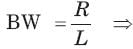
A resistance of 7 ohm is connected in series with an inductance of 31.8mH. The circuit is connected to a 100V 50Hz sinusoidal supply. Calculate the current in the circuit.- a)2.2 A
- b)4.2 A
- c)6.2 A
- d)8.2 A
Correct answer is option 'D'. Can you explain this answer?
A resistance of 7 ohm is connected in series with an inductance of 31.8mH. The circuit is connected to a 100V 50Hz sinusoidal supply. Calculate the current in the circuit.
a)
2.2 A
b)
4.2 A
c)
6.2 A
d)
8.2 A
| | Dishani Bose answered |
Given: Resistance (R) = 7 ohm, Inductance (L) = 31.8mH = 0.0318 H, Voltage (V) = 100V, Frequency (f) = 50Hz
Formula used: Impedance of the circuit (Z) = √(R² + Xl²), where Xl = 2πfL (inductive reactance)
Calculation:
- Xl = 2πfL = 2π*50*0.0318 = 10 ohm (inductive reactance)
- Z = √(R² + Xl²) = √(7² + 10²) = 12.2 ohm (impedance)
- Current (I) = V/Z = 100/12.2 = 8.2 A (ampere)
Therefore, the current in the circuit is 8.2 A. Hence, option D is the correct answer.
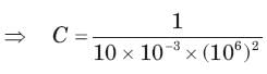
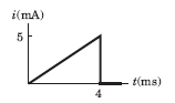
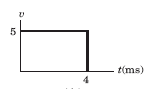
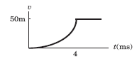
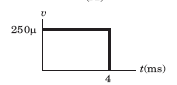
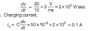
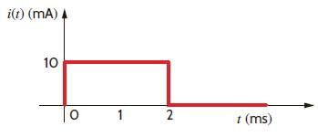
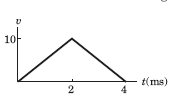
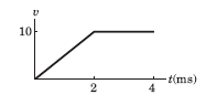
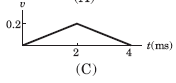
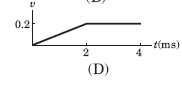
Can you explain the answer of this question below:The waveform for the current in a 200 μF capacitor is shown in fig. The waveform for the capacitor voltage is
- A:
- B:
- C:
- D:
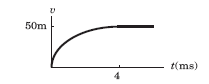
The answer is b.
The waveform for the current in a 200 μF capacitor is shown in fig. The waveform for the capacitor voltage is
| | Arnab Mehra answered |
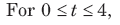

= 3125t2
At t = 4 ms, vc = 0.05 V
It will be parabolic path. at t = 0 t-axis will be tangent.
A power factor of a circuit can be improved by placing which, among the following, in a circuit?- a)Inductor
- b)Capacitor
- c)Resistor
- d)Switch
Correct answer is option 'B'. Can you explain this answer?
A power factor of a circuit can be improved by placing which, among the following, in a circuit?
a)
Inductor
b)
Capacitor
c)
Resistor
d)
Switch
| | Srestha Kumar answered |
Improving Power Factor in a Circuit with Capacitors
Introduction:
The power factor of a circuit measures the efficiency of power usage. A power factor of 1 means all power supplied to the circuit is being used effectively, while a power factor less than 1 means that some of the power is being lost as a result of reactive power. Reactive power is the power that is used to maintain the electric and magnetic fields of the circuit, but does not perform any useful work.
One way to improve the power factor of a circuit is by adding capacitors. Capacitors are able to store and release electrical energy, which can help to offset the reactive power in a circuit. This results in a more efficient use of power, and a higher power factor.
How Capacitors Improve Power Factor:
Capacitors work by storing electrical energy in an electric field. When a voltage is applied to a capacitor, it charges up, and stores energy. When the voltage is removed, the capacitor discharges, and releases the stored energy. This charging and discharging cycle is repeated continuously as long as there is a voltage applied to the capacitor.
When a circuit has a low power factor, it means that there is a lot of reactive power being used. This reactive power is caused by inductive loads in the circuit, such as motors and transformers. Inductive loads cause the current to lag behind the voltage, which results in a phase shift between the two. This phase shift results in a lower power factor.
By adding capacitors to the circuit, the reactive power caused by inductive loads can be offset. Capacitors are able to supply reactive power to the circuit, which helps to cancel out the reactive power caused by inductive loads. This results in a more efficient use of power, and a higher power factor.
Conclusion:
Adding capacitors to a circuit is an effective way to improve the power factor. Capacitors are able to supply reactive power to the circuit, which helps to offset the reactive power caused by inductive loads. This results in a more efficient use of power, and a higher power factor.
Which of the following is not true about the circuit shown below?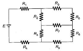
- a)Number of nodes for the above circuit is 8.
- b)Number of branches for the above circuit is 6.
- c)Number of meshes for the above circuit is 3.
- d)Number of junction points for the above circuit is 6
Correct answer is option 'D'. Can you explain this answer?
Which of the following is not true about the circuit shown below?
a)
Number of nodes for the above circuit is 8.
b)
Number of branches for the above circuit is 6.
c)
Number of meshes for the above circuit is 3.
d)
Number of junction points for the above circuit is 6
| | Abhay Khanna answered |
Number of junction point for the given circuit is 6.
Can you explain the answer of this question below:Twelve 6 Ω resistor are used as edge to form a cube.The resistance between two diagonally opposite corner of the cube is
- A:
5/6 Ω
- B:
6/5 Ω
- C:
5 Ω
- D:
6 Ω
The answer is c.
Twelve 6 Ω resistor are used as edge to form a cube.The resistance between two diagonally opposite corner of the cube is
5/6 Ω
6/5 Ω
5 Ω
6 Ω
 | Shivam Sharma answered |
Current i will be split into 3 branch currents.
Since the resistance is same (i.e. 6 Ω), Current in each branch will be i/3.
This i/3 current will in turn split into 2 branch currents each of value i/6.

The current between 2 diagonally opposite side will be composed of two i/3 currents and one i/6 current.
(i/3) + (i/3) + (i/6) = 5i/6 ==>(V/R)
V = 5i; Req= V/i = 5i/i = 5Ω

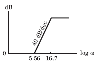
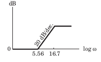
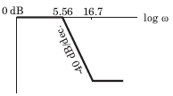
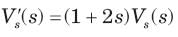
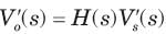
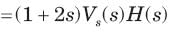
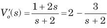
Bode diagram of the network function Vo /Vs for the circuit of fig. is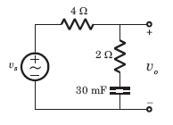
- a)
- b)
- c)
- d)
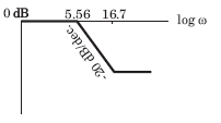
Correct answer is option 'D'. Can you explain this answer?
Bode diagram of the network function Vo /Vs for the circuit of fig. is
a)
b)
c)
d)
| | Yash Patel answered |
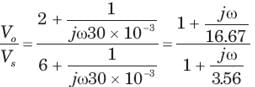
-20 dB/decade line starting from ω = 5.56 rad/s
20 dB/decade line starting from ω = 16.67 rad/s
Hence -20 dB/decade line for 5.56 < ω < 16.67 parallel to ω axis to ω >16.67

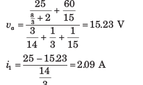
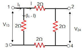
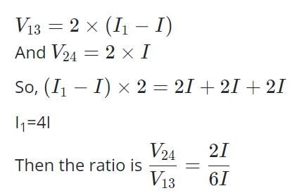
i1 = ?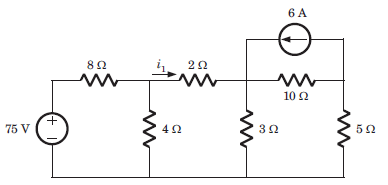
- a)3.3 A
- b)2.1 A
- c)1.7 A
- d)1.1 A
Correct answer is option 'A'. Can you explain this answer?
i1 = ?
a)
3.3 A
b)
2.1 A
c)
1.7 A
d)
1.1 A
| | Sanya Agarwal answered |
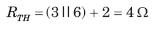
sing Thevenin equivalent and source transform

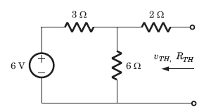
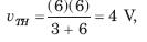
RTH=? 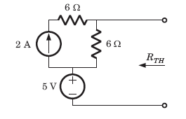
- a)3Ω
- b)12 Ω
- c)6 Ω
- d) ∞
Correct answer is option 'C'. Can you explain this answer?
RTH=?
a)
3Ω
b)
12 Ω
c)
6 Ω
d)
∞
 | Shabnam Sharma answered |
Correct answer is a
What is the total capacitance when two capacitors C1 and C2 are connected in series?- a)(C1 + C2) / C1*C2
- b)(1/C1) + (1/C2)
- c)C1 * C2 / (C1 + C2)
- d)C1 + C2
Correct answer is option 'C'. Can you explain this answer?
What is the total capacitance when two capacitors C1 and C2 are connected in series?
a)
(C1 + C2) / C1*C2
b)
(1/C1) + (1/C2)
c)
C1 * C2 / (C1 + C2)
d)
C1 + C2
| | Preethi Banerjee answered |
Capacitors in Series
When capacitors are connected in series, the total capacitance can be calculated using the following formula:
1/C = 1/C1 + 1/C2 + 1/C3 + ...
Where C is the total capacitance and C1, C2, C3, etc. are the capacitances of the individual capacitors.
Calculating Total Capacitance
In the case of two capacitors connected in series (C1 and C2), the formula becomes:
1/C = 1/C1 + 1/C2
To find the total capacitance (C), we can rearrange the formula:
1/C = (1/C1)*(1/C2) / (1/C1 + 1/C2)
Multiplying both sides by the denominator:
C = (C1 * C2) / (C1 + C2)
Therefore, the correct answer is option C: C1 * C2 / (C1 + C2).
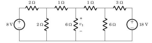
In the circuit given, a charge of 600 C is delivered to the 100 V source in a 1 minute. The value of v1 must be: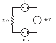
- a)240 V
- b)120 V
- c)60 V
- d)30 V
Correct answer is option 'A'. Can you explain this answer?
In the circuit given, a charge of 600 C is delivered to the 100 V source in a 1 minute. The value of v1 must be:
a)
240 V
b)
120 V
c)
60 V
d)
30 V
| | Amar Choudhury answered |
- In order for 600 C charge to be delivered to the 100 V source, the current must be anticlockwise.
- Applying KVL we get:
v1 + 60 - 100 = 10 x 20
v1 = 240 V
The voltage response of a network to a unit step input is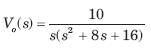 The response is
- a)under damped
- b)over damped
- c)critically damped
- d)can’t be determined
Correct answer is option 'C'. Can you explain this answer?
The voltage response of a network to a unit step input is
The response is
a)
under damped
b)
over damped
c)
critically damped
d)
can’t be determined
| | Yash Patel answered |
The characteristic equation is s(s2 + 8s + 16) = 0 , (s + 4)2 = 0, s = -4, -4
Being real and repeated root, it is critically damped.
Which of the following statements associated with capacitor is wrong?- a)A capacitor resists an abrupt change in the voltage across it in a manner analogous to the way a spring resists abrupt change in its displacement.
- b)A capacitor resists an abrupt change in the. current flowing through it.
- c)It is impossible to change the voltage across a capacitor even if the current through the capacitor changes by a finite amount in zero time, for this requires infinite current through the capacitor.
- d)A finite amount of energy can be stored in a capacitor even if the current through the capacitor is zero, such as when the voltage across it is constant.
Correct answer is option 'B'. Can you explain this answer?
Which of the following statements associated with capacitor is wrong?
a)
A capacitor resists an abrupt change in the voltage across it in a manner analogous to the way a spring resists abrupt change in its displacement.
b)
A capacitor resists an abrupt change in the. current flowing through it.
c)
It is impossible to change the voltage across a capacitor even if the current through the capacitor changes by a finite amount in zero time, for this requires infinite current through the capacitor.
d)
A finite amount of energy can be stored in a capacitor even if the current through the capacitor is zero, such as when the voltage across it is constant.
| | Nandita Bajaj answered |
Statement (b) holds true for an inductor not for a capacitor.
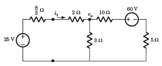
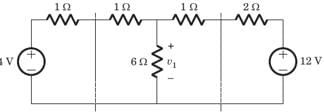
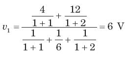
Can you explain the answer of this question below:v1 = ?
- A:
6 V
- B:
7 V
- C:
8 V
- D:
10 V
The answer is a.
v1 = ?
6 V
7 V
8 V
10 V
| | Zoya Sharma answered |
If we solve this circuit direct, we have to deal with three variable. But by simple manipulation variable can be reduced to one. By changing the LHS and RHS in Thevenin equivalent
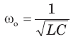
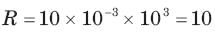
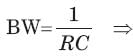
A parallel resonant circuit has a resistance of 2 kΩ and half power frequencies of 86 kHz and 90 kHz.1. The value of capacitor is- a)6 μF
- b)20 nF
- c)2 nF
- d)60 μF
Correct answer is 'B'. Can you explain this answer?
A parallel resonant circuit has a resistance of 2 kΩ and half power frequencies of 86 kHz and 90 kHz.1. The value of capacitor is
a)
6 μF
b)
20 nF
c)
2 nF
d)
60 μF
 | Asha Deshpande answered |
BW = ω2 - ω1 = 2π(90 - 86)k = 8π krad/s
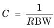
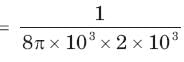
= 19.89 nF
= 19.89 nF
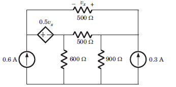
vx = ?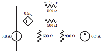
- a)9 V
- b)-9 V
- c)10 V
- d)-10 V
Correct answer is option 'D'. Can you explain this answer?
vx = ?
a)
9 V
b)
-9 V
c)
10 V
d)
-10 V
 | Machine Experts answered |
Let i1 and i2 be two loop current
The three impedances Z1 = 20∠30⁰Ω, Z2 = 40∠60⁰Ω, Z3 = 10∠-90⁰Ω are delta-connected to a 400V, 3 – Ø system. Find the phase current IY.- a)(10 - j0) A
- b)(10 + j0) A
- c)(-10 + j0) A
- d)(-10 - j0) A
Correct answer is option 'C'. Can you explain this answer?
The three impedances Z1 = 20∠30⁰Ω, Z2 = 40∠60⁰Ω, Z3 = 10∠-90⁰Ω are delta-connected to a 400V, 3 – Ø system. Find the phase current IY.
a)
(10 - j0) A
b)
(10 + j0) A
c)
(-10 + j0) A
d)
(-10 - j0) A
| | Dipanjan Nambiar answered |
Understanding Delta Connection
In a delta connection, the line voltage is equal to the phase voltage. Given the line voltage V_L = 400V, the phase voltage V_Ph is also 400V.
Calculating Phase Currents
The phase currents for each impedance are calculated using Ohm's Law:
I_Ph = V_Ph / Z
Where Z is the impedance of each phase.
Given Impedances
- Z1 = 20∠30° (in polar form)
- Z2 = 40∠60°
- Z3 = 10∠-90°
Convert Impedances to Rectangular Form
- Z1 = 20(cos 30° + j sin 30°) = 20(0.866 + j0.5) = 17.32 + j10
- Z2 = 40(cos 60° + j sin 60°) = 40(0.5 + j0.866) = 20 + j34.64
- Z3 = 10(cos -90° + j sin -90°) = 10(0 - j1) = 0 - j10
Calculate Phase Currents
Now, calculate the phase current IY corresponding to Z2:
IY = V_Ph / Z2 = 400V / (20 + j34.64)
To simplify, multiply the numerator and denominator by the conjugate of the denominator:
IY = 400(20 - j34.64) / (20^2 + (34.64)^2)
Calculating the denominator:
- 20^2 + (34.64)^2 = 400 + 1200.57 = 1600.57
Calculating the numerator:
- 400(20 - j34.64) = 8000 - j13856
Now, divide by the denominator:
IY = (8000 - j13856) / 1600.57 = -10 + j0 (approximately)
Conclusion
Therefore, the phase current IY is approximately -10 + j0 A, confirming that the correct answer is option 'C'.
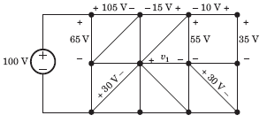
Can you explain the answer of this question below:Consider the circuit graph shown in fig. Each branch of circuit graph represent a circuit element. The value of voltage v1 is
- A:
-30 V
- B:
25 V
- C:
-20 V
- D:
15 V
The answer is d.
Consider the circuit graph shown in fig. Each branch of circuit graph represent a circuit element. The value of voltage v1 is
-30 V
25 V
-20 V
15 V
 | Kaavya Sengupta answered |
100 = 65 + V2 => V2 = 35 V
V3 – 30 = V2 => V3 = 65 V
105 – V3 + V4 – 65 = 0 => V4 = 25 V
V4 + 15 – 55 + V1 = 0 => V1 = 15 V.

KVL is applied in _______- a)Mesh analysis
- b)Nodal analysis
- c)Both mesh and nodal
- d)Neither mesh nor nodal
Correct answer is option ''. Can you explain this answer?
KVL is applied in _______
a)
Mesh analysis
b)
Nodal analysis
c)
Both mesh and nodal
d)
Neither mesh nor nodal
| | Ishan Chawla answered |
KVL stands for Kirchhoff's Voltage Law, which is a fundamental principle in electrical circuit analysis. It is based on the principle of conservation of energy and is used to determine the voltages across different elements in a circuit.
KVL applies to both mesh analysis and nodal analysis, making option (c) "Both mesh and nodal" the correct answer.
Explanation:
1. KVL in Mesh Analysis:
- Mesh analysis is a method used to analyze circuits with multiple loops.
- In this method, the circuit is divided into meshes or loops, and KVL is applied to each mesh separately.
- KVL states that the sum of voltage drops around any closed loop in a circuit is equal to the sum of voltage rises.
- By applying KVL to each mesh, a set of equations can be obtained that relate the voltage drops across the elements in the circuit.
- These equations can then be solved simultaneously to determine the unknown currents in the circuit.
2. KVL in Nodal Analysis:
- Nodal analysis is a method used to analyze circuits with multiple nodes.
- In this method, the circuit is divided into nodes, and KVL is applied to each node separately.
- KVL states that the sum of currents entering a node is equal to the sum of currents leaving the node.
- By applying KVL to each node, a set of equations can be obtained that relate the currents at different nodes in the circuit.
- These equations can then be solved simultaneously to determine the unknown node voltages in the circuit.
3. Importance of KVL:
- KVL is a fundamental principle in circuit analysis and is used to determine the voltages across different elements in a circuit.
- It is based on the principle of conservation of energy, which states that the total energy in a closed system remains constant.
- By applying KVL, we can ensure that the energy flow in a circuit is conserved and the circuit obeys the laws of physics.
- KVL is essential in determining the voltage drops across resistors, capacitors, inductors, and other circuit elements, which are crucial for designing and analyzing electrical circuits.
In conclusion, KVL is applied in both mesh analysis and nodal analysis, making option (c) "Both mesh and nodal" the correct answer. It is a fundamental principle in circuit analysis that ensures the conservation of energy in electrical circuits.
Find the value of the currents I1 and I2 flowing clockwise in the first and second mesh respectively.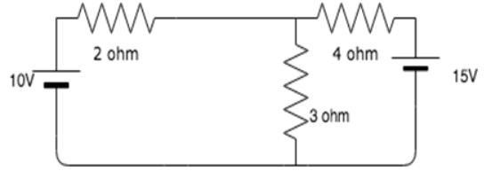
- a)0.96A, 1.73A
- b)-0.96A, -1.73A
- c)-0.96A, 1.73A
- d)0.96A, -1.73A
Correct answer is option 'D'. Can you explain this answer?
Find the value of the currents I1 and I2 flowing clockwise in the first and second mesh respectively.
a)
0.96A, 1.73A
b)
-0.96A, -1.73A
c)
-0.96A, 1.73A
d)
0.96A, -1.73A
| | Sanvi Kapoor answered |
The two mesh equations are:
5I1 - 3I2 = 10
-3I1 + 7I2 = -15
Solving the equations simultaneously, we get I1 = 0.96A and I2 = -1.73A.
5I1 - 3I2 = 10
-3I1 + 7I2 = -15
Solving the equations simultaneously, we get I1 = 0.96A and I2 = -1.73A.
Of the two methods of loop and node variable analysis- a)loop analysis is always preferable,
- b)node analysis is always preferable.
- c)loop analysis may be preferable in some situations while node analysis may be preferable in other situations.
- d)there is nothing to choose between them
Correct answer is option 'B'. Can you explain this answer?
Of the two methods of loop and node variable analysis
a)
loop analysis is always preferable,
b)
node analysis is always preferable.
c)
loop analysis may be preferable in some situations while node analysis may be preferable in other situations.
d)
there is nothing to choose between them
| | Parth Ghoshal answered |
Loop analysis vs Node analysis in Electrical Engineering
Loop and node analysis are two methods used in electrical engineering to analyze circuits. Both methods involve applying Kirchhoff's laws to determine the voltages and currents in a circuit. However, there are some differences between the two methods that make one preferable over the other in certain situations.
Loop Analysis
Loop analysis involves analyzing a circuit by creating loops or closed paths in the circuit. The analysis involves applying Kirchhoff's voltage law (KVL) to each loop to determine the voltages in the circuit. Loop analysis is generally used in circuits that have a small number of loops and a large number of nodes. It is also useful when the circuit has voltage sources.
Node Analysis
Node analysis involves analyzing a circuit by creating nodes or junctions in the circuit. The analysis involves applying Kirchhoff's current law (KCL) to each node to determine the currents in the circuit. Node analysis is generally used in circuits that have a small number of nodes and a large number of loops. It is also useful when the circuit has current sources.
Which method is preferable?
The answer to this question depends on the circuit being analyzed. However, in general, node analysis is always preferable over loop analysis. This is because node analysis is a more general method that can be used to analyze any circuit, while loop analysis is only suitable for certain types of circuits.
Additionally, node analysis is a more efficient method than loop analysis. This is because it involves solving a smaller number of simultaneous equations, which makes the analysis faster and easier. Node analysis is also more intuitive than loop analysis, as it involves analyzing the circuit at the points where the currents flow.
Conclusion
In conclusion, both loop analysis and node analysis are useful methods for analyzing circuits in electrical engineering. However, node analysis is generally considered to be the more preferable method due to its generality, efficiency, and intuitiveness.
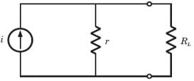
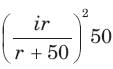
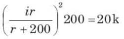
Find the value of R1.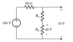
- a)25 Ω
- b)50 Ω
- c)100 Ω
- d)2000 Ω
Correct answer is option 'C'. Can you explain this answer?
Find the value of R1.
a)
25 Ω
b)
50 Ω
c)
100 Ω
d)
2000 Ω
| | Raghavendra Patel answered |
- Voltage across 60 Ω resistor = 30 V
- Current = 30 / 60 = 0.5 A
- Voltage across R1 is = (70 - 20) V = 50 V
- R1 = 50 / 0.5 = 100 Ω
 , the response would be
 ⇒
⇒ 
 ⇒
⇒ 
 ⇒
⇒ 
At a certain current, the energy stored in iron cored coil is 1000 J and its copper loss is 2000 W. The time constant (in second) of the coil is- a)0.25
- b)0.5
- c)1.0
- d)2.0
Correct answer is option 'C'. Can you explain this answer?
At a certain current, the energy stored in iron cored coil is 1000 J and its copper loss is 2000 W. The time constant (in second) of the coil is
a)
0.25
b)
0.5
c)
1.0
d)
2.0
| | Ameya Nambiar answered |
Calculation of Inductance and Resistance
Firstly, we need to calculate the inductance and resistance of the iron cored coil using the given information:
- Energy stored in the coil = 1000 J
- Copper loss = 2000 W
- Time constant = L/R
We know that the energy stored in an inductor is given by the formula:
E = 0.5 * L * I^2
where E is the energy stored, L is the inductance, and I is the current.
From the given information, we can rearrange the above formula to get the inductance:
L = 2 * E / I^2
L = 2 * 1000 / I^2
L = 2000 / I^2
Next, we need to calculate the resistance of the coil using the power loss formula:
P = I^2 * R
where P is the power loss and R is the resistance.
From the given information, we can rearrange the above formula to get the resistance:
R = P / I^2
R = 2000 / I^2
Calculation of Time Constant
We can now calculate the time constant of the coil using the formula:
Time constant = L / R
Time constant = (2000 / I^2) / (2000 / I^2)
Time constant = 1
Therefore, the time constant of the iron cored coil is 1 second, which is option C.
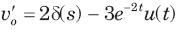
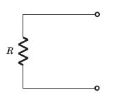
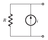
A simple equivalent circuit of the 2 terminal network shown in fig. is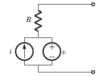
- a)
- b)
- c)
- d)
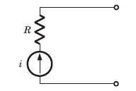
Correct answer is option 'B'. Can you explain this answer?
A simple equivalent circuit of the 2 terminal network shown in fig. is
a)
b)
c)
d)
| | Avinash Sharma answered |
After killing all source equivalent resistance is R
Open circuit voltage = v1
Open circuit voltage = v1
In a two element series circuit, the applied voltage and the resulting current are v(t) = 60 + 66 sin (1000t) V, i(t) = 2.3sin (1000t + 68.3) 3 A. The nature of the elements would be- a)R C
- b)L C
- c)R L
- d)R R
Correct answer is option 'A'. Can you explain this answer?
In a two element series circuit, the applied voltage and the resulting current are v(t) = 60 + 66 sin (1000t) V, i(t) = 2.3sin (1000t + 68.3) 3 A. The nature of the elements would be
a)
R C
b)
L C
c)
R L
d)
R R
| | Kaavya Sengupta answered |
RC circuit causes a positive shift in the circuit.

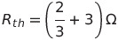
The circuit given below.The Thevenin resistance across the diode in the circuit is?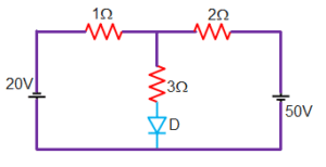 The Thevenin resistance across the diode in the circuit is?
- a) 12/5 Ω
- b) 11/5 Ω
- c) 11/4 Ω
- d) 11/3 Ω
Correct answer is option 'D'. Can you explain this answer?
The circuit given below.The Thevenin resistance across the diode in the circuit is?
The Thevenin resistance across the diode in the circuit is?
a)
12/5 Ω
b)
11/5 Ω
c)
11/4 Ω
d)
11/3 Ω
| | Anjana Singh answered |
Diode is non-linear elements is removed.
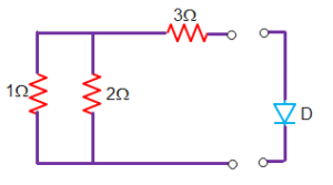
After shorting the voltage source the redrawn circuit is
Thevenin resistance
= 11/3 ohm
The voltage across a capacitor is given by
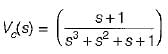
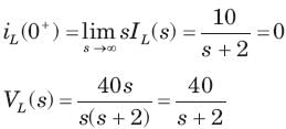
If the capacitor has the value of 2 F, initial value of current through it (at t = 0+) will be- a)1 A
- b)0 A
- c)2 A
- d)None of these
Correct answer is option 'C'. Can you explain this answer?
The voltage across a capacitor is given by
If the capacitor has the value of 2 F, initial value of current through it (at t = 0+) will be
If the capacitor has the value of 2 F, initial value of current through it (at t = 0+) will be
a)
1 A
b)
0 A
c)
2 A
d)
None of these
| | Rhea Reddy answered |
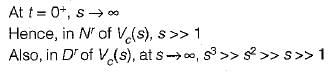
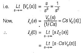
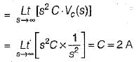
Hence, initial value of current through the capacitor = 2 A.
For a 2-port symmetrical bilateral network, iftransmission parameters A = 3 and B = 1Ω , the value ofparameter C is- a)3
- b)8 S
- c)8
- d)9
Correct answer is option 'B'. Can you explain this answer?
For a 2-port symmetrical bilateral network, iftransmission parameters A = 3 and B = 1Ω , the value ofparameter C is
a)
3
b)
8 S
c)
8
d)
9
| | Shivam Sharma answered |
For symmetrical network A = D = 3
For bilateral AD – BC = 1
9 – C = 1
C = 8
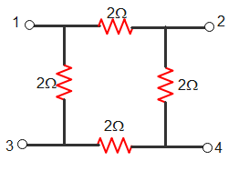
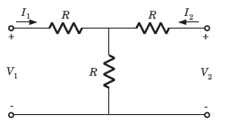
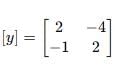
Consider the two-port network shown in the figure.

- a)y11=2,y12=−4,y21=−4,y22=2
- b)y11=2,y12=−4,y21=−1,y22=2
- c)y11=1,y12=−2,y21=−1,y22=3
- d)y11=2,y12=−4,y21=−4,y22=3
Correct answer is option 'B'. Can you explain this answer?
Consider the two-port network shown in the figure.

a)
y11=2,y12=−4,y21=−4,y22=2
b)
y11=2,y12=−4,y21=−1,y22=2
c)
y11=1,y12=−2,y21=−1,y22=3
d)
y11=2,y12=−4,y21=−4,y22=3
 | Starcoders answered |

Write KCL at
V₁
V₁
I₁ = V₁/1 + V₁ - V₂/1 - 3V₂
I₁ = 2V₁ - 4V₂
I₁ = 2V₁ - 4V₂
Write KCL at
V₂
V₂
I₂ = V₂/1 + V₂ - V₁/1
I₂ = -V₁ + 2V₂
I₂ = -V₁ + 2V₂
A solid copper sphere, 10 cm in diameter is deprived of 1020 electrons by a charging scheme. The charge on the sphere is- a)160.2 C
- b)-160.2 C
- c)16.02 C
- d)-16.02 C
Correct answer is 'C'. Can you explain this answer?
A solid copper sphere, 10 cm in diameter is deprived of 1020 electrons by a charging scheme. The charge on the sphere is
a)
160.2 C
b)
-160.2 C
c)
16.02 C
d)
-16.02 C
 | Anirban Khanna answered |
N 10^20, Q = ne = e 10^20 = 16.02 C.Charge on sphere will be positive.
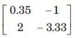
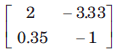
[T] = ?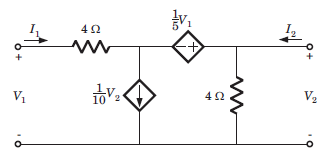
- a)
- b)
- c)

- d)
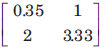
Correct answer is option 'C'. Can you explain this answer?
[T] = ?
a)
b)
c)
d)
| | Avinash Sharma answered |
Let I3 be the clockwise loop current in center loop
 V2 = 4(I2 + I3) ⇒ I3 = 0.25V2 - I2
⇒ I1 = 0.35V2 - I2 .........(i)
V1 = 4I1 - 0.2V1 + V2
1.2V1 = 4(0.35V2 - I2) + V2 = 2.4V2 - 4I2
⇒ V1 = 2V2 - 3.33I2 .........(ii)
V2 = 4(I2 + I3) ⇒ I3 = 0.25V2 - I2⇒ I1 = 0.35V2 - I2 .........(i)
V1 = 4I1 - 0.2V1 + V2
1.2V1 = 4(0.35V2 - I2) + V2 = 2.4V2 - 4I2
⇒ V1 = 2V2 - 3.33I2 .........(ii)
An Inductor works as a ________ circuit for DC supply.- a)Open
- b)Short
- c)Polar
- d)Non-polar
Correct answer is option 'B'. Can you explain this answer?
An Inductor works as a ________ circuit for DC supply.
a)
Open
b)
Short
c)
Polar
d)
Non-polar
| | Lavanya Menon answered |
Induced voltage across an inductor is zero if the current flowing through it is constant, i.e. Inductor works as a short circuit for DC supply.

Chapter doubts & questions for Network Theory (Electric Circuits) - 6 Months Preparation for GATE Electrical 2026 is part of Electrical Engineering (EE) exam preparation. The chapters have been prepared according to the Electrical Engineering (EE) exam syllabus. The Chapter doubts & questions, notes, tests & MCQs are made for Electrical Engineering (EE) 2026 Exam. Find important definitions, questions, notes, meanings, examples, exercises, MCQs and online tests here.
Chapter doubts & questions of Network Theory (Electric Circuits) - 6 Months Preparation for GATE Electrical in English & Hindi are available as part of Electrical Engineering (EE) exam. Download more important topics, notes, lectures and mock test series for Electrical Engineering (EE) Exam by signing up for free.
6 Months Preparation for GATE Electrical675 videos|1390 docs|885 tests |