


All Exams > Electrical Engineering (EE) > 6 Months Preparation for GATE Electrical > All Questions
All questions of Power Systems for Electrical Engineering (EE) Exam


Series capacitive compensation on EHV transmission lines is used to- a)reduce the line loading
- b)improve the protection of the line
- c)reduce the voltage profile
- d)improve the stability of the system
Correct answer is option 'D'. Can you explain this answer?
Series capacitive compensation on EHV transmission lines is used to
a)
reduce the line loading
b)
improve the protection of the line
c)
reduce the voltage profile
d)
improve the stability of the system
| | Prasenjit Yadav answered |
With series capacitive compensation, the net transfer reactance of the line will be X = (XL - XC) due to which the power transmitted from sending to the receiving end is increased. Thus, it will improve the steady-state stability of the system.
If the positive, negative and zero-sequence reactance of an element of a power system are 0.3, 0.3 and 0.8 p.u. respectively, then the element would be a?- a)Synchronous generator
- b)Synchronous motor
- c)Static load
- d)Transmission line
Correct answer is option 'D'. Can you explain this answer?
If the positive, negative and zero-sequence reactance of an element of a power system are 0.3, 0.3 and 0.8 p.u. respectively, then the element would be a?
a)
Synchronous generator
b)
Synchronous motor
c)
Static load
d)
Transmission line
| | Jyoti Basak answered |
Sequence Reactance Overview
Sequence reactance is a crucial concept in power system analysis, particularly for unbalanced fault conditions. It helps in understanding how different system components behave under various operating conditions.
Types of Reactance
- Positive Sequence Reactance (X1): Represents the behavior of the system under balanced conditions.
- Negative Sequence Reactance (X2): Represents the response to unbalanced loads or faults where currents are in opposite phase.
- Zero Sequence Reactance (X0): Indicates the behavior of the system under conditions where all phases are affected equally, such as in ground faults.
Given Values
- Positive Sequence Reactance (X1) = 0.3 p.u.
- Negative Sequence Reactance (X2) = 0.3 p.u.
- Zero Sequence Reactance (X0) = 0.8 p.u.
Analysis of the Values
In this case, the positive and negative sequence reactances being equal (0.3 p.u.) suggests that the element behaves symmetrically under balanced conditions, which is typical for synchronous machines. However, the significantly higher zero-sequence reactance (0.8 p.u.) indicates a different characteristic.
Element Identification
- Synchronous Generator and Motor: Typically have similar positive and negative sequence reactances but a much lower zero-sequence reactance, as they are not designed to handle unbalanced conditions well.
- Static Load: Would have low or negligible reactances, making it unlikely in this context.
- Transmission Line: It generally displays higher zero-sequence reactance due to its capacitance and inductance characteristics, particularly in unbalanced conditions.
Conclusion
Given the equal positive and negative sequence reactances combined with a higher zero-sequence reactance, the element is best identified as a Transmission Line. This is because transmission lines are designed to manage both balanced and unbalanced conditions effectively, making option 'D' the correct choice.
Which is the conventional source of energy?- a)Solar
- b)Radio-active substances
- c)Geothermal
- d)Wind
Correct answer is option 'B'. Can you explain this answer?
Which is the conventional source of energy?
a)
Solar
b)
Radio-active substances
c)
Geothermal
d)
Wind
| | Juhi Joshi answered |
Conventional source of energy are: Water, Coal, Gas, radioactive substances. Non-conventional source of energy are: Wind, Solar energy, Geothermal.
Shunt capacitance in an EHV line is restored to- a)improve the stability
- b)reduce fault level
- c)improve the voltage
- d)none of the above
Correct answer is option 'C'. Can you explain this answer?
Shunt capacitance in an EHV line is restored to
a)
improve the stability
b)
reduce fault level
c)
improve the voltage
d)
none of the above
| | Ayush Kumar answered |
Shunt capacitor is usually connected at load end for improving power factor and voltage.
A single-phase, two wire transmission line, 15 km long, is made up of round conductors, each 0.8 cm radius, separated from each other by 40 cm. The equivalent diameter of a fictitious hollow, thin-walled conductor having the same inductance as the original line is given by- a)1.557 cm '
- b)1.246 cm
- c)1.6 cm
- d)0.623 cm
Correct answer is option 'B'. Can you explain this answer?
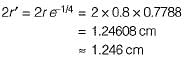
A single-phase, two wire transmission line, 15 km long, is made up of round conductors, each 0.8 cm radius, separated from each other by 40 cm. The equivalent diameter of a fictitious hollow, thin-walled conductor having the same inductance as the original line is given by
a)
1.557 cm '
b)
1.246 cm
c)
1.6 cm
d)
0.623 cm
| | Avik Iyer answered |
The fictitious conductor is one whose radius is r' and whose diameter is therefore,
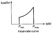
Operating transmission lines close to their maximum power transfer capability will impair- a)stability
- b)steady state power flow
- c)voltage profile
- d)transmission efficiency
Correct answer is option 'A'. Can you explain this answer?
Operating transmission lines close to their maximum power transfer capability will impair
a)
stability
b)
steady state power flow
c)
voltage profile
d)
transmission efficiency
| | Bijoy Nair answered |
**Explanation:**
Operating transmission lines close to their maximum power transfer capability can impair stability due to various factors. Let's explore these factors in detail:
**1. Voltage Stability:**
When transmission lines are operated near their maximum power transfer capability, the voltage at the receiving end of the line may drop significantly. This drop in voltage can lead to voltage instability, causing voltage collapse or even voltage instability in the entire power system. Voltage instability can result in voltage sags, flickering lights, and potential blackouts.
**2. Transient Stability:**
Transient stability refers to the ability of the power system to maintain synchronism after a disturbance. Operating transmission lines close to their maximum power transfer capability can reduce the margin of stability, making the system more susceptible to disturbances and reducing the ability to recover from them. This can lead to cascading failures and blackouts in the power system.
**3. Oscillatory Stability:**
Oscillatory stability refers to the ability of the power system to maintain stable oscillations after a disturbance. Operating transmission lines close to their maximum power transfer capability can reduce the damping of oscillations, leading to increased oscillatory instability. This can result in sustained oscillations, voltage fluctuations, and potential system instability.
**4. Control and Protection Issues:**
Operating transmission lines close to their maximum power transfer capability can also create control and protection issues. The protective relays may have a shorter operating time, resulting in slower fault clearance. This delay in fault clearance can lead to increased fault durations, potential equipment damage, and system instability.
**5. Voltage Regulation:**
Operating transmission lines close to their maximum power transfer capability can also affect the voltage profile of the power system. Voltage regulation becomes challenging as the transmission lines approach their maximum power transfer capability. Voltage drops along the transmission lines can result in inadequate voltage levels at load centers, affecting the efficient operation of electrical equipment and causing voltage stability issues.
**Conclusion:**
In conclusion, operating transmission lines close to their maximum power transfer capability can impair stability in the power system. It can lead to voltage instability, transient instability, oscillatory instability, control and protection issues, and voltage regulation challenges. Therefore, it is essential to operate transmission lines within their safe operating limits to ensure the stability and reliability of the power system.
In which part of the thermal power plant, the steam pressure is less than that of atmosphere?- a)Boiler
- b)Turbine
- c)Superheater
- d)Condenser
Correct answer is option 'D'. Can you explain this answer?
In which part of the thermal power plant, the steam pressure is less than that of atmosphere?
a)
Boiler
b)
Turbine
c)
Superheater
d)
Condenser
| | Zoya Sharma answered |
Condenser in a steam power plant has lowest operating pressure.
Shunt reactors are needed- a)to boost receiving end voltage under light loads.
- b)to boost receiving end voltage under heavy loads.
- c)to bring down receiving end voltage at light loads.
- d)to bring down receiving end voltage under heavy loads.
Correct answer is option 'C'. Can you explain this answer?
Shunt reactors are needed
a)
to boost receiving end voltage under light loads.
b)
to boost receiving end voltage under heavy loads.
c)
to bring down receiving end voltage at light loads.
d)
to bring down receiving end voltage under heavy loads.
| | Kiran Iyer answered |
Shunt reactors are used to bring down receiving end voltage during light load or no-load condition to overcome Ferranti effect.
For a synchronous phase modifier the load angle is- a)00
- b)250
- c)300
- d)None of these
Correct answer is option 'A'. Can you explain this answer?
For a synchronous phase modifier the load angle is
a)
00
b)
250
c)
300
d)
None of these
| | Arya Mukherjee answered |
Synchronous phase modifier is an overexcited synchronous motor operating on no-load under wide variation of excitation. For no-load operation, δ = 0.
Consider the following phenomenon occuring in a power system:
1. Corona loss
2. Charging current
3. Ferranti effect
4. Dielectric loss
5. Skin effect
Which of the above are associated with transmission lines?- a)1,3 and 5
- b)2, 3, 4 and 5
- c)3, 2 and 4
- d)1,2, 3 and 5
Correct answer is option 'D'. Can you explain this answer?
Consider the following phenomenon occuring in a power system:
1. Corona loss
2. Charging current
3. Ferranti effect
4. Dielectric loss
5. Skin effect
Which of the above are associated with transmission lines?
1. Corona loss
2. Charging current
3. Ferranti effect
4. Dielectric loss
5. Skin effect
Which of the above are associated with transmission lines?
a)
1,3 and 5
b)
2, 3, 4 and 5
c)
3, 2 and 4
d)
1,2, 3 and 5
| | Gargi Basak answered |
Dielectric loss occurs in underground cables not in a transmission line.
Consider the following statements:
1. AAC (All Aluminium conductors) are universaly employed for feeders as well as distributors.
2. The conductor size for a feeder is mainly governed by the permissible voltage drop in the line.
Which of the above statement(s) is/are true?- a)1 only
- b)1 and 2
- c)none
- d)2 only
Correct answer is option 'C'. Can you explain this answer?
Consider the following statements:
1. AAC (All Aluminium conductors) are universaly employed for feeders as well as distributors.
2. The conductor size for a feeder is mainly governed by the permissible voltage drop in the line.
Which of the above statement(s) is/are true?
1. AAC (All Aluminium conductors) are universaly employed for feeders as well as distributors.
2. The conductor size for a feeder is mainly governed by the permissible voltage drop in the line.
Which of the above statement(s) is/are true?
a)
1 only
b)
1 and 2
c)
none
d)
2 only
| | Isha Singh answered |
ACSR conductors are universally employed for distribution systems (feeders as well as distributors), AAC can be used for distribution purpose provided the spans are small.
Hence, statement-1 is false.
The conductor size for a feeder is mainly governed by current carrying capacity and overall economy. Hence, 2 is also a false statement.
Hence, statement-1 is false.
The conductor size for a feeder is mainly governed by current carrying capacity and overall economy. Hence, 2 is also a false statement.
The resistance and reactance of a short line are equal. At zero regulation the load will be- a)upf
- b)zpf
- c)0.707 lag
- d)0.707 lead
Correct answer is option 'D'. Can you explain this answer?
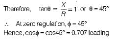
The resistance and reactance of a short line are equal. At zero regulation the load will be
a)
upf
b)
zpf
c)
0.707 lag
d)
0.707 lead
| | Harsh Kulkarni answered |
Zero regulation of a transmission line occurs at a leading power factor when φ = θ.
Since R = X
Since R = X
Series capacitors on transmission lines are of little use when- a)the load VAR requirement is small
- b)the load VAR requirement is large
- c)the load VAR requirement is fluctuating
- d)none of the above
Correct answer is option 'B'. Can you explain this answer?
Series capacitors on transmission lines are of little use when
a)
the load VAR requirement is small
b)
the load VAR requirement is large
c)
the load VAR requirement is fluctuating
d)
none of the above
| | Debanshi Basak answered |
Correct Answer :- a
Explanation : If the load var requirement is small, series capacitors are of little help.
The insulation resistance of a cable of 10 km length is 1 MΩ. The resistance for a length of 40 km is- a)1 MΩ
- b)4 MΩ
- c)0.25 MΩ
- d)Can’t be determined
Correct answer is option 'C'. Can you explain this answer?
The insulation resistance of a cable of 10 km length is 1 MΩ. The resistance for a length of 40 km is
a)
1 MΩ
b)
4 MΩ
c)
0.25 MΩ
d)
Can’t be determined
| | Tanishq Majumdar answered |
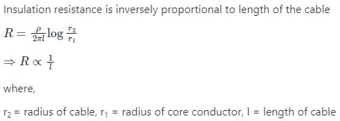
l1 = 10 km, R1 = 1 MΩ, l2 = 40 km

1/R2 = 40/10
R2 = 1/4 = 0.25 MΩ
Suppose IA, IB and IC are a set of unbalanced current phasors in a three-phase system. The phase-B zero-sequence current IB0 = 0.1 ∠0° p.u. If phase-A current IA = 1.1 ∠0° p.u. and phase-C current IC = (1 ∠120° + 0.1) p.u. then IB in p.u. is- a)1 ∠240° - 0.1 ∠0°
- b)1.1 ∠240° - 0.1 ∠0°
- c)1.1 ∠-120° + 0.1 ∠0°
- d)1 ∠-120° + 0.1 ∠0°
Correct answer is option 'D'. Can you explain this answer?
Suppose IA, IB and IC are a set of unbalanced current phasors in a three-phase system. The phase-B zero-sequence current IB0 = 0.1 ∠0° p.u. If phase-A current IA = 1.1 ∠0° p.u. and phase-C current IC = (1 ∠120° + 0.1) p.u. then IB in p.u. is
a)
1 ∠240° - 0.1 ∠0°
b)
1.1 ∠240° - 0.1 ∠0°
c)
1.1 ∠-120° + 0.1 ∠0°
d)
1 ∠-120° + 0.1 ∠0°
| | Manoj Mehra answered |
Based on the given information, we know that the phase-B zero-sequence current IB0 is equal to 0.1.
Zero-sequence currents are the currents that flow in the neutral conductor of a three-phase system. In a balanced system, the zero-sequence currents are generally zero. However, in an unbalanced system, these currents can be non-zero.
Since IB0 is specified as 0.1, we can conclude that there is a non-zero phase-B zero-sequence current present in the system.
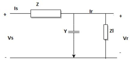
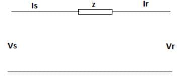
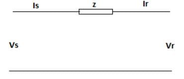
The transmission line equations are given by the below set of equations based on the line diagram as given. Identify the missing term marked as ’?’.
Vs = A*Vr + B*Ir
Is = C*Vr + ?*Ir
- a)1+YZ
- b)Z
- c)Y
- d)1
Correct answer is option 'D'. Can you explain this answer?
The transmission line equations are given by the below set of equations based on the line diagram as given. Identify the missing term marked as ’?’.
Vs = A*Vr + B*Ir
Is = C*Vr + ?*Ir
Vs = A*Vr + B*Ir
Is = C*Vr + ?*Ir
a)
1+YZ
b)
Z
c)
Y
d)
1
| | Pooja Patel answered |
Using KVL to the line diagram,
Vs = (1+YZ)*Vr + Z*Ir
Is = Y*Vr + Ir.
Vs = (1+YZ)*Vr + Z*Ir
Is = Y*Vr + Ir.
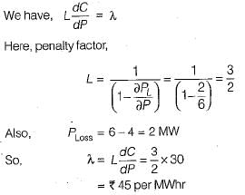
A generator is supplying a load. An incremental change in load of 4 MW requires generation to be increased by 6 MW. The cost at plant bus is ₹ 30/MWhr. The incremental cost at the receiving end is- a)₹ 30/MWhr
- b)₹ 5/MWhr
- c)₹ 33.4/MWhr
- d)₹ 6.0/MWhr
Correct answer is option 'B'. Can you explain this answer?
A generator is supplying a load. An incremental change in load of 4 MW requires generation to be increased by 6 MW. The cost at plant bus is ₹ 30/MWhr. The incremental cost at the receiving end is
a)
₹ 30/MWhr
b)
₹ 5/MWhr
c)
₹ 33.4/MWhr
d)
₹ 6.0/MWhr
| | Raj Desai answered |
The power output from a hydro-electric power plant doesn’t depend on- a)discharge
- b)head
- c)type of turbine
- d)system efficiency
Correct answer is option 'C'. Can you explain this answer?
The power output from a hydro-electric power plant doesn’t depend on
a)
discharge
b)
head
c)
type of turbine
d)
system efficiency
| | Sanskriti Desai answered |
Power output of a hydroelectric plant
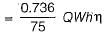
Here,
Here,
For an arcing fault where the arc resistance is significant an impedance or admittance relay will- a)over reach
- b)under reach
- c)the reach of relay is unaffected
- d)the reach will depend on the arcing resistance and may under reach or over reach.
Correct answer is option 'B'. Can you explain this answer?
For an arcing fault where the arc resistance is significant an impedance or admittance relay will
a)
over reach
b)
under reach
c)
the reach of relay is unaffected
d)
the reach will depend on the arcing resistance and may under reach or over reach.
| | Jatin Mukherjee answered |
The reach of a reactance relay is unaffected due to the arc resistance while an impedance and admittance relay under reaches.
In case of HVDC system, there is- a)both skin effect and corona loss
- b)skin effect but no corona loss
- c)corona loss but no skin effect
- d)neither corona loss nor skin effect
Correct answer is option 'C'. Can you explain this answer?
In case of HVDC system, there is
a)
both skin effect and corona loss
b)
skin effect but no corona loss
c)
corona loss but no skin effect
d)
neither corona loss nor skin effect
| | Lakshmi Desai answered |
Corona loss and skin effect are two important phenomena that occur in high voltage direct current (HVDC) systems. The correct answer to the question is option 'C', which states that there is corona loss but no skin effect in a HVDC system. Let's explain this answer in detail:
1. Corona Loss:
- Corona loss is the power loss that occurs due to the ionization of the surrounding air around the conductors in a high voltage system.
- In HVDC systems, the voltage levels are very high, which increases the likelihood of corona discharge.
- When the electric field intensity exceeds a certain threshold, the air molecules around the conductor break down and become ionized, resulting in a corona discharge.
- This corona discharge leads to power loss and can cause interference with communication systems.
- Corona loss is more significant in AC systems compared to DC systems because the polarity reversal in AC systems helps in the recovery of the ionized air molecules.
- However, in HVDC systems, the polarity remains constant, which leads to a continuous corona loss.
2. Skin Effect:
- Skin effect is the tendency of alternating current (AC) to flow near the surface of a conductor, causing the effective cross-sectional area available for current flow to decrease.
- Skin effect occurs due to the self-induced magnetic field generated by the current flowing through the conductor.
- The magnetic field repels the current from the center of the conductor, causing it to concentrate near the surface.
- Skin effect is significant in AC systems, where the current alternates direction periodically.
- In DC systems, the current flows in one direction, and there is no significant skin effect.
Therefore, in the case of HVDC systems:
- There is corona loss because of the high voltage levels and continuous polarity, which leads to corona discharge and power loss.
- There is no skin effect because the DC current flows in one direction, and there is no significant alternating magnetic field that causes the current to concentrate near the surface of the conductor.
Hence, option 'C' is the correct answer, which states that there is corona loss but no skin effect in HVDC systems.
The percent bias for a generator protection lies between- a)15 to 20%
- b)10 to 15%
- c)5 to 10%
- d)None of these
Correct answer is option 'A'. Can you explain this answer?
The percent bias for a generator protection lies between
a)
15 to 20%
b)
10 to 15%
c)
5 to 10%
d)
None of these
| | Niharika Basu answered |
Explanation:
Generator protection is an essential aspect of power system operation to ensure the safety and reliability of the power system. One of the critical parameters in generator protection is the percent bias.
The percent bias is a measure of the difference between the actual and expected values of the measured quantity. In generator protection, the measured quantity is the current or voltage, and the expected value is the threshold or setting value of the protection relay.
The percent bias is calculated as follows:
Percent bias = [(Measured value - Expected value) / Expected value] x 100
Ideally, the percent bias should be zero, indicating that the measured value is equal to the expected value. However, due to various factors such as instrument errors, temperature variations, and external interferences, some degree of bias is inevitable.
The acceptable range of percent bias for generator protection is typically between 15 to 20%. This range ensures that the protection relay operates reliably and does not trip unnecessarily due to small variations in the measured value.
If the percent bias is too low, the protection relay may not operate when it should, leading to a potential failure of the generator or other equipment. On the other hand, if the percent bias is too high, the protection relay may trip unnecessarily, leading to a disruption of power supply and unnecessary maintenance.
Therefore, it is essential to ensure that the percent bias of generator protection is within the acceptable range of 15 to 20%. Regular testing and calibration of the protection system can help to maintain the accuracy and reliability of the protection system.
Conclusion:
In conclusion, the acceptable range of percent bias for generator protection is between 15 to 20%. This range ensures that the protection relay operates reliably and does not trip unnecessarily due to small variations in the measured value. Regular testing and calibration of the protection system can help to maintain the accuracy and reliability of the protection system.
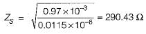
A three-phase, 50 Hz, 400 kV, transmission line is 300 km long. The line inductance is 0.97 mH/km per phase and capacitance is 0.0115 μF/km per phase. Assuming a lossless line, the surge impedance of the line will be- a)196.44 Ω
- b)286.62 Ω
- c)250 Ω
- d)290.43 Ω
Correct answer is option 'D'. Can you explain this answer?
A three-phase, 50 Hz, 400 kV, transmission line is 300 km long. The line inductance is 0.97 mH/km per phase and capacitance is 0.0115 μF/km per phase. Assuming a lossless line, the surge impedance of the line will be
a)
196.44 Ω
b)
286.62 Ω
c)
250 Ω
d)
290.43 Ω
| | Samarth Khanna answered |
Surge impedance of the line is given by

or,
or,
The critical clearing angle of a power system is related to- a)reactive power limit
- b)short circuit limit
- c)steady state stability limit
- d)transient stability limit
Correct answer is option 'D'. Can you explain this answer?
The critical clearing angle of a power system is related to
a)
reactive power limit
b)
short circuit limit
c)
steady state stability limit
d)
transient stability limit
| | Kunal Sharma answered |
tcr and δcr are related to transient stability limit. The fault in a power system must be cleared before δ reaches δcr and before tcr.
The line current flowing in the lines toward a balanced load connected in delta are Ia = 100∠0°, Ib = 141.4∠225°, Ic = 100∠90°. Find the symmetrical component of the line current.- a)Ia0 = 0.07∠115°, Ia1 = 121∠150°, Ia2 = 209.88∠5°
- b)Ia0 = 7∠125°, Ia1 = 211∠125°, Ia2 = 229.88∠150°
- c)Ia0 = 0.007∠45°, Ia1 = 111∠15°, Ia2 = 29.88∠105°
- d)Ia0 = 0.7∠145°, Ia1 = 131∠105°, Ia2 = 290.88∠10°
Correct answer is option 'C'. Can you explain this answer?
The line current flowing in the lines toward a balanced load connected in delta are Ia = 100∠0°, Ib = 141.4∠225°, Ic = 100∠90°. Find the symmetrical component of the line current.
a)
Ia0 = 0.07∠115°, Ia1 = 121∠150°, Ia2 = 209.88∠5°
b)
Ia0 = 7∠125°, Ia1 = 211∠125°, Ia2 = 229.88∠150°
c)
Ia0 = 0.007∠45°, Ia1 = 111∠15°, Ia2 = 29.88∠105°
d)
Ia0 = 0.7∠145°, Ia1 = 131∠105°, Ia2 = 290.88∠10°
| | Tarun Chawla answered |
It seems like the sentence is incomplete. The line current flowing in the lines toward a balanced load connected in delta can be represented by three variables: Ia, Ib, and Ic. In this case, you have provided the value of Ia as 100. However, without the values of Ib and Ic, it is not possible to provide further information or calculate the total line current. Please provide additional information or clarify your question.
For a fully transposed transmission line- a)positive, negative and zero sequence impedances are equal.
- b)positive and negative sequence impedances are equal.
- c)zero and positive sequence impedances are equal.
- d)negative and zero sequence impedances are equal
Correct answer is option 'B'. Can you explain this answer?
For a fully transposed transmission line
a)
positive, negative and zero sequence impedances are equal.
b)
positive and negative sequence impedances are equal.
c)
zero and positive sequence impedances are equal.
d)
negative and zero sequence impedances are equal
| | Janhavi Roy answered |
Explanation:
A fully transposed transmission line is a line where the positive, negative, and zero-sequence impedances are equal. Let's understand this concept in detail.
1. Positive Sequence Impedance:
The positive sequence impedance represents the impedance of the transmission line when all three phases have the same magnitude and rotate in the same direction. It is denoted by Z1.
2. Negative Sequence Impedance:
The negative sequence impedance represents the impedance of the transmission line when the three phases have the same magnitude but rotate in the opposite direction. It is denoted by Z2.
3. Zero Sequence Impedance:
The zero sequence impedance represents the impedance of the transmission line when all three phases have zero magnitude. It is denoted by Z0.
Equality of Positive and Negative Sequence Impedances (Option B):
In a fully transposed transmission line, the positive and negative sequence impedances are equal. This is because the line is designed to have symmetrical characteristics, and the impedance seen by the positive and negative sequence currents is the same. Therefore, option B is correct.
Equality of Zero and Positive Sequence Impedances (Option C):
In a fully transposed transmission line, the zero and positive sequence impedances are not necessarily equal. The zero sequence impedance depends on the arrangement of conductors and ground, while the positive sequence impedance represents the impedance of the line under normal operating conditions. Therefore, option C is incorrect.
Equality of Negative and Zero Sequence Impedances (Option D):
In a fully transposed transmission line, the negative and zero sequence impedances are not necessarily equal. The negative sequence impedance represents the impedance of the line when the three phases rotate in the opposite direction, while the zero sequence impedance represents the impedance when all three phases have zero magnitude. Therefore, option D is incorrect.
To summarize, in a fully transposed transmission line, the positive and negative sequence impedances are equal, while the zero sequence impedance can be different.
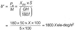
If the initial acceleration power of a 100 MVA, 50 Hz synchronous generator having H= 5 MJ/MVA is Xpu, the initial acceleration in elec-deg/s2 and the inertia constant in M J-s/ele-deg respectively will be - a)31.4X, 18
- b)1800X, 0.056
- c)X/1800, 0.056
- d)X/31.4, 18
Correct answer is option 'B'. Can you explain this answer?
If the initial acceleration power of a 100 MVA, 50 Hz synchronous generator having H= 5 MJ/MVA is Xpu, the initial acceleration in elec-deg/s2 and the inertia constant in M J-s/ele-deg respectively will be
a)
31.4X, 18
b)
1800X, 0.056
c)
X/1800, 0.056
d)
X/31.4, 18
| | Maulik Choudhury answered |
From swing equation,
Also, inertia constant,
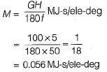
Also, inertia constant,
The series impedance matrix of a short three-phase transmission line in phase coordinates is 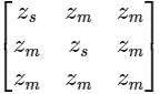 . If the positive sequence impedance is (1 + j 10) Ω, and the zero sequence is (4 + j 31) Ω, then the imaginary part of Zm (in Ω) is _______ (up to 2 decimal places).
Correct answer is '7'. Can you explain this answer?
The series impedance matrix of a short three-phase transmission line in phase coordinates is . If the positive sequence impedance is (1 + j 10) Ω, and the zero sequence is (4 + j 31) Ω, then the imaginary part of Zm (in Ω) is _______ (up to 2 decimal places).
. If the positive sequence impedance is (1 + j 10) Ω, and the zero sequence is (4 + j 31) Ω, then the imaginary part of Zm (in Ω) is _______ (up to 2 decimal places).| | Pooja Patel answered |
Given that, positive sequence impedance (Z1) = (1 + j10) Ω
Zero sequence impedance (Z0) = (4 + j31) Ω
We know that, Z1 = Zs – Zm
and Z0 = Zs + 2Zm
Z1 = 1 + j10 = Zs – Zm → (1)
and Z0 = 4 + j31 = Zs + 2Zm → (2)
from equations (1) and (2)
⇒ Zm = 1 + j7
Imaginary part of Zm = 7 Ω.
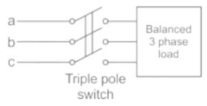
A balanced 3-phase load is supplied from a 3-phase supply. The contact in line c of the triple pole switch contactor fails to connect when switched on. If the line currents in lines a and b record 25A each, then the positive sequence component of the current is
- a)14.4 ∠30° A
- b)25.0 ∠-30° A
- c)14.4 ∠-30° A
- d)25 ∠80° A
Correct answer is option 'C'. Can you explain this answer?
A balanced 3-phase load is supplied from a 3-phase supply. The contact in line c of the triple pole switch contactor fails to connect when switched on. If the line currents in lines a and b record 25A each, then the positive sequence component of the current is
a)
14.4 ∠30° A
b)
25.0 ∠-30° A
c)
14.4 ∠-30° A
d)
25 ∠80° A
 | Naroj Boda answered |
The contact in line C of the triple pole switch contactor fails to connect when switched on.
⇒ Ic = 0 A
And Ia + Ib = 0
⇒ Ia = -Ib
⇒ Ia = 25 ∠0°, Ib = 25 ∠-180°
Positive sequence current,
Positive sequence current,
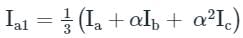
= 1/3(25 ∠ 0∘ + 1∠120 × 25∠ −180)
= 14.4 ∠ -30°
For a 35 km transmission line having a lumped impedance of the line as 20 ohms, is required to be shown in the ABCD form, it is given as- a)

- b)

- c)

- d)

Correct answer is option 'A'. Can you explain this answer?
For a 35 km transmission line having a lumped impedance of the line as 20 ohms, is required to be shown in the ABCD form, it is given as
a)
b)
c)
d)
 | Pioneer Academy answered |
From the given length, it is a short TL. Hence,
Then ABCD paramteres of this circuit is
Then ABCD paramteres of this circuit is
There is a problem of high transient over voltages while interrupting- a)capacitive currents
- b)inductive currents
- c)heavy short circuit current
- d)(a) or (c)
Correct answer is option 'A'. Can you explain this answer?
There is a problem of high transient over voltages while interrupting
a)
capacitive currents
b)
inductive currents
c)
heavy short circuit current
d)
(a) or (c)
| | Palak Verma answered |
High transient over voltages occurs in power system due to formation of capacitance across the breaker poles. These are also called switching over voltages.
When generating units are loaded to equal incremental costs, it results in- a)minimum fuel costs
- b)fuel costs are at a maximum
- c)fuel costs are not affected
- d)maximum loading of generating units
Correct answer is option 'A'. Can you explain this answer?
When generating units are loaded to equal incremental costs, it results in
a)
minimum fuel costs
b)
fuel costs are at a maximum
c)
fuel costs are not affected
d)
maximum loading of generating units
| | Parth Ghoshal answered |
To minimize the total fuel cost, the generating units must operate at equal incremental cost of production.
For which of the following element the positive, negative and zero sequence impedances are equal- a)Transmission lines
- b)Transformer
- c)Alternator
- d)None of the above
Correct answer is option 'B'. Can you explain this answer?
For which of the following element the positive, negative and zero sequence impedances are equal
a)
Transmission lines
b)
Transformer
c)
Alternator
d)
None of the above
| | Pooja Patel answered |
Sequence Impedance:
- The sequence impedance of the network describes the behavior of the system under asymmetrical fault conditions.
Positive Sequence Impedance
- The impedance offered by the network to the flow of positive sequence current is called the positive sequence impedance.
- The positive sequence means all the electrical quantities are numerically equal and displaces each other by 120º.
Negative Sequence Impedance
- The negative sequence impedance means the impedance offered by the network to the flows of the negative sequence current.
Zero Sequence Impedance
- The impedance offered to zero sequence current is called the zero sequence impedance.
- Generally, resistance offered by the power system is less when compared to reactance.
- So, the resistance of the system is neglected and reactance is considered.
Values of sequence reactance of some equipment are as follows:
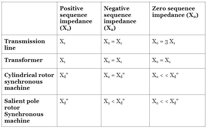
Where,
X0 is the zero sequence reactance
X1 is the positive sequence reactance
X2 is the negative sequence reactance
Xd” is the direct axis reactance
X0 is the zero sequence reactance
X1 is the positive sequence reactance
X2 is the negative sequence reactance
Xd” is the direct axis reactance
The simplified ABCD representation of a 40 km transmission line is best given as- a)

- b)

- c)

- d)

Correct answer is option 'A'. Can you explain this answer?
The simplified ABCD representation of a 40 km transmission line is best given as
a)
b)
c)
d)
| | Pooja Patel answered |
From the given length, it is a short TL. Hence,
Then ABCD parameters of this circuit is
Then ABCD parameters of this circuit is
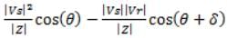
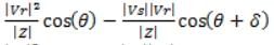
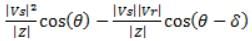
The maximum power delivered to the load for short transmission line is at- a)β = α
- b)β > α
- c)β = δ
- d)β > δ
Correct answer is option 'C'. Can you explain this answer?
The maximum power delivered to the load for short transmission line is at
a)
β = α
b)
β > α
c)
β = δ
d)
β > δ
| | Ritika Mukherjee answered |
The sending end
b) the receiving end
c) the midpoint of the line
d) both the sending and receiving ends
b) the receiving end
c) the midpoint of the line
d) both the sending and receiving ends
The line current in a three phase unbalanced load are Ia = 4 + j6, Ib = 2 - j2, Ic = -3 + j2, then zero sequence component of current will be- a)3 + j6
- b)9 + j10
- c)1 + j2
- d)3 - j6
Correct answer is option 'C'. Can you explain this answer?
The line current in a three phase unbalanced load are Ia = 4 + j6, Ib = 2 - j2, Ic = -3 + j2, then zero sequence component of current will be
a)
3 + j6
b)
9 + j10
c)
1 + j2
d)
3 - j6
| | Pooja Patel answered |
Concept:
The relation between the line currents in terms of the symmetrical components of currents is given below.
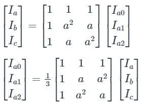
The relation between the line currents in terms of the symmetrical components of currents is given below.
Ia0 = Zero Sequence Component of Current
Ia1 = Positive Sequence Component of Current
Ia2 = Negative Sequence Component of Current
a = 1∠120°, which represents the rotation of 120° in the clockwise direction.
a2 = 1∠-120° or 1∠240° in anticlockwise direction or clockwise direction, respectively.
1 + a + a2 = 0
Calculation:
Given that
Ia = 4 + j6, Ib = 2 - j2, Ic = -3 + j2
Zero sequence component of current,
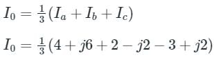
∴ I0 = 1 + j2 A
HVDC transmission is preferred to EHV AC because- a)HVDC terminal equipment are inexpensive
- b)VAR compensation is not required in HVDC system
- c)system reliability can be improved
- d)harmonic problem is avoided
Correct answer is option 'C'. Can you explain this answer?
HVDC transmission is preferred to EHV AC because
a)
HVDC terminal equipment are inexpensive
b)
VAR compensation is not required in HVDC system
c)
system reliability can be improved
d)
harmonic problem is avoided
| | Hrishikesh Yadav answered |
HVDC transmission is more reliable than EHV AC because it uses ground or sea return and therefore, in case of fault on a line it can still be used to supply power with the help of healthy lines.
Fast acting excitation systems- a)improve transient stability.
- b)improve steady state stability.
- c)both (a) and (b).
- d)have no effect on stability of the system.
Correct answer is option 'A'. Can you explain this answer?
Fast acting excitation systems
a)
improve transient stability.
b)
improve steady state stability.
c)
both (a) and (b).
d)
have no effect on stability of the system.
| | Shivam Das answered |
Fast field excitation system is one of the method to improve transient stability of the system.
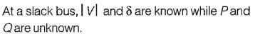
The slack bus has to be a- a)PV bus
- b)PQ bus
- c)QV bus
- d)No constraint
Correct answer is option 'A'. Can you explain this answer?
The slack bus has to be a
a)
PV bus
b)
PQ bus
c)
QV bus
d)
No constraint
| | Arpita Banerjee answered |
Out of the 15% of Generator buses in a power system, one bus is taken as a slack bus which take care of losses occuring in the system. At a generator bus P and V are known. Hence, a slack bus can be a PV bus.
Bundled conductors in a transmission line will- a)reduce line loading.
- b)improve steady state stability.
- c)improve protection of line.
- d)reduce voltage of buses at the two ends.
Correct answer is option 'B'. Can you explain this answer?
Bundled conductors in a transmission line will
a)
reduce line loading.
b)
improve steady state stability.
c)
improve protection of line.
d)
reduce voltage of buses at the two ends.
| | Ritika Sarkar answered |
Bundled conductors increases self GMD due to which the series inductive reactance is reduced as a result of which power transferred from sending end to the receiving end is increased. Hence, it improves the steady state stability of the system.
A balanced 3-phase system consists of -- a)Zero sequence currents only
- b)Positive sequence currents only
- c)Negative and zero sequence currents
- d)Zero, negative and positive sequence currents
Correct answer is option 'B'. Can you explain this answer?
A balanced 3-phase system consists of -
a)
Zero sequence currents only
b)
Positive sequence currents only
c)
Negative and zero sequence currents
d)
Zero, negative and positive sequence currents
 | Swati Patel answered |
Answer:
A balanced 3-phase system consists of positive sequence currents only. This means that the three phases of the system have equal magnitudes and are 120 degrees apart from each other in terms of phase angle. The positive sequence currents represent the normal operating conditions of a 3-phase system.
Explanation:
To understand why a balanced 3-phase system consists of positive sequence currents only, let's first understand what positive, negative, and zero sequence currents are.
Positive Sequence Currents:
- In a balanced 3-phase system, the positive sequence currents are the currents that flow in the same sequence and magnitude in all three phases.
- These currents have a phase angle of 120 degrees between each other.
- The positive sequence currents represent the normal operating conditions of a 3-phase system.
Negative Sequence Currents:
- The negative sequence currents are the currents that flow in the opposite sequence as the positive sequence currents.
- These currents have a phase angle of -120 degrees between each other.
- Negative sequence currents can occur due to imbalances in the system, such as unbalanced loads or faults.
Zero Sequence Currents:
- The zero sequence currents are the currents that flow in all three phases in the same direction and at the same magnitude.
- These currents have a phase angle of 0 degrees between each other.
- Zero sequence currents can occur due to imbalances in the system, such as unbalanced loads or faults.
Why a balanced 3-phase system consists of positive sequence currents only:
- A balanced 3-phase system is designed to have equal magnitudes and 120 degrees phase angle separation between the three phases.
- Under normal operating conditions, the loads in a balanced 3-phase system are also balanced, meaning they draw equal currents from each phase.
- When the loads are balanced and the system is operating normally, there are no imbalances that would cause the flow of negative or zero sequence currents.
- Therefore, in a balanced 3-phase system, only positive sequence currents are present.
In conclusion, a balanced 3-phase system consists of positive sequence currents only because under normal operating conditions, the loads are balanced, and there are no imbalances that would cause the flow of negative or zero sequence currents.
Assumption of decoupling is valid only if- a)XLine < RLine
- b)XLine = RLine
- c)Any conditon
- d)RLine >> XLine
Correct answer is option 'D'. Can you explain this answer?
Assumption of decoupling is valid only if
a)
XLine < RLine
b)
XLine = RLine
c)
Any conditon
d)
RLine >> XLine
| | Samarth Khanna answered |
Assumption of decoupling is valid in load flow study only if resistance of the line is negligible in comparison to the reactance of the line.
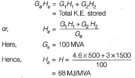
A 500-MVA synchronous machine has H1 = 4.6 MJ/MVA, and a 1500 MVA machine has H2 = 3.0 MJ/MVA. The two machines operate in parallel in a power station. The equivalent H constant for the two, relative to a 100 MVA base will be- a)22 MJ/MVA
- b)45 MJ/MVA
- c)52 MJ/MVA
- d)68 MJ/MVA
Correct answer is option 'D'. Can you explain this answer?
A 500-MVA synchronous machine has H1 = 4.6 MJ/MVA, and a 1500 MVA machine has H2 = 3.0 MJ/MVA. The two machines operate in parallel in a power station. The equivalent H constant for the two, relative to a 100 MVA base will be
a)
22 MJ/MVA
b)
45 MJ/MVA
c)
52 MJ/MVA
d)
68 MJ/MVA
| | Anoushka Choudhury answered |
We know that,
Full load compensation in a line requires- a)shunt reactors
- b)transformers
- c)shunt capacitors
- d)series capacitors
Correct answer is option 'C'. Can you explain this answer?
Full load compensation in a line requires
a)
shunt reactors
b)
transformers
c)
shunt capacitors
d)
series capacitors
| | Sharmila Bajaj answered |
Full load compensation in a line requires shunt capacitors for improving power factor of the system.
Chapter doubts & questions for Power Systems - 6 Months Preparation for GATE Electrical 2026 is part of Electrical Engineering (EE) exam preparation. The chapters have been prepared according to the Electrical Engineering (EE) exam syllabus. The Chapter doubts & questions, notes, tests & MCQs are made for Electrical Engineering (EE) 2026 Exam. Find important definitions, questions, notes, meanings, examples, exercises, MCQs and online tests here.
Chapter doubts & questions of Power Systems - 6 Months Preparation for GATE Electrical in English & Hindi are available as part of Electrical Engineering (EE) exam. Download more important topics, notes, lectures and mock test series for Electrical Engineering (EE) Exam by signing up for free.
6 Months Preparation for GATE Electrical675 videos|1390 docs|885 tests |