


All Exams > Electrical Engineering (EE) > 6 Months Preparation for GATE Electrical > All Questions
All questions of Electromagnetic Fields Theory for Electrical Engineering (EE) Exam
Find the time constant of a capacitor with capacitance of 2 microfarad having an internal resistance of 4 megaohm.- a)2
- b)0.5
- c)8
- d)0.25
Correct answer is option 'C'. Can you explain this answer?
Find the time constant of a capacitor with capacitance of 2 microfarad having an internal resistance of 4 megaohm.
a)
2
b)
0.5
c)
8
d)
0.25
| | Sanvi Kapoor answered |
Answer: c
Explanation: The time constant of capacitor is given by T = RC, where R = 4×10⁶ and C = 2×10⁻⁶. Thus T = 4×106 x2x10-6 = 8 seconds.
Explanation: The time constant of capacitor is given by T = RC, where R = 4×10⁶ and C = 2×10⁻⁶. Thus T = 4×106 x2x10-6 = 8 seconds.

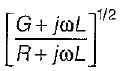
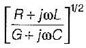
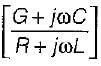
'The characteristic impedance Z0 of a transmission line is given by (where R, L, G, C are the unit length parameters)- a)
- b)

- c)
- d)
Correct answer is option 'C'. Can you explain this answer?
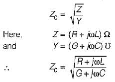
'The characteristic impedance Z0 of a transmission line is given by (where R, L, G, C are the unit length parameters)
a)
b)
c)
d)
| | Sanya Agarwal answered |
The characteristic impedance (Z0) of a transmission line is given by
Which components exist in an electromagnetic wave?- a)Only E
- b)Only H
- c)Both E and H
- d)Neither E or H
Correct answer is option 'C'. Can you explain this answer?
Which components exist in an electromagnetic wave?
a)
Only E
b)
Only H
c)
Both E and H
d)
Neither E or H
| | Sanvi Kapoor answered |
Answer: c
Explanation: In an electromagnetic wave, the electric and magnetic components coexist. They propagate perpendicular to each other and to the direction of propagation in space.
Explanation: In an electromagnetic wave, the electric and magnetic components coexist. They propagate perpendicular to each other and to the direction of propagation in space.
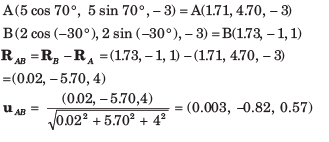
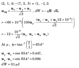
Two points in cylindrical coordinates are A(ρ = 5, Ø = 700 , z = -3) and B(ρ = 2, Ø = 300 , z = 1) A unit vector at A towards B is- a) 0.03ux - 0.82uy + 0.57uz
- b) 0.03ux + 0.82uy + 0.57uz
- c) - 0.03ux + 0.82uy + 0.57uz
- d) 0.003ux - 0.82uy + 0.57uz
Correct answer is option 'D'. Can you explain this answer?
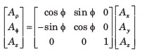
Two points in cylindrical coordinates are A(ρ = 5, Ø = 700 , z = -3) and B(ρ = 2, Ø = 300 , z = 1) A unit vector at A towards B is
a)
0.03ux - 0.82uy + 0.57uz
b)
0.03ux + 0.82uy + 0.57uz
c)
- 0.03ux + 0.82uy + 0.57uz
d)
0.003ux - 0.82uy + 0.57uz
| | Ravi Singh answered |
In cartesian coordinates:
The reflection coefficient of a transmission line with a short-circuited load is - a)infinite
- b)1∠1800
- c)zero
- d)none of these
Correct answer is option 'B'. Can you explain this answer?
The reflection coefficient of a transmission line with a short-circuited load is
a)
infinite
b)
1∠1800
c)
zero
d)
none of these
| | Rhea Reddy answered |
For a short-circuited load,
reflection coefficient of voltage
and reflection coefficient of current,
Here, only option (b) matches the answer
reflection coefficient of voltage
and reflection coefficient of current,
Here, only option (b) matches the answer


A transmission line whose characteristic impedance is purely resistive- a)must be lossless line
- b)must be a distortionless line
- c)may not be a lossless line
- d)may not be a distortionless line
Correct answer is option 'A'. Can you explain this answer?
A transmission line whose characteristic impedance is purely resistive
a)
must be lossless line
b)
must be a distortionless line
c)
may not be a lossless line
d)
may not be a distortionless line
 | Starcoders answered |
If the transmission line is to have neither frequency nor delay distortion, then α (attenuation constant) and velocity of propagation cannot be functions of frequency.
V = ω/β β
must be a direct function of frequency to achieve this condition
LG = CR
L/C = R/G
z0 = √((R + jωL)/(G + jωC))
For a lossless line,
z0 = √(L/C)
α = √(RG) = 0 for R = 0, G = 0
β = ω√(LC)
A loss less line is always a distortion less line.
V = ω/β β
must be a direct function of frequency to achieve this condition
LG = CR
L/C = R/G
z0 = √((R + jωL)/(G + jωC))
For a lossless line,
z0 = √(L/C)
α = √(RG) = 0 for R = 0, G = 0
β = ω√(LC)
A loss less line is always a distortion less line.
A material has
σ = 0 and εr = 1. The magnetic field intensity is H = 4cos ( 106t - 0.01z)μy A/m.Que: The electric field intensity E is- a)4.52 sin(106 t - 0.01z) kV/m
- b)4.52 sin(106 t + 0.01z) kV/m
- c)4.52 cos(106 t - 0.01z) kV/m
- d)4.52 cos(106 t + 0.01z) kV/m
Correct answer is option 'A'. Can you explain this answer?
A material has
σ = 0 and εr = 1. The magnetic field intensity is H = 4cos ( 106t - 0.01z)μy A/m.
Que: The electric field intensity E is
a)
4.52 sin(106 t - 0.01z) kV/m
b)
4.52 sin(106 t + 0.01z) kV/m
c)
4.52 cos(106 t - 0.01z) kV/m
d)
4.52 cos(106 t + 0.01z) kV/m
| | Akash Patel answered |
Explanation:
Given:
H = 4cos (106t - 0.01z)y A/m
To find:
The electric field intensity E
We know that the relationship between magnetic field intensity H and electric field intensity E is given by the equation:
E = ρH
Where ρ is the intrinsic impedance of the material.
Given that the material has ρ = 0, we can substitute this value into the equation:
E = 0 × H = 0
Therefore, the electric field intensity E is zero.
Since none of the options provided in the question match the correct answer, none of the options are correct.
A rectangular loop of wire in free space joins points A(1, 0, 1) to B(3, 0, 1) to C(3, 0, 4) to D(1, 0, 4) to A. The wire carries a current of 6 mA flowing in the uz direction from B to C. A filamentary current of 15 A flows along the entire z, axis in the uz directions.Que: The force on side AB is- a)23.4 ux μN
- b)16.4 ux μN
- c)19.8 ux nN
- d)26.3 ux nN
Correct answer is option 'C'. Can you explain this answer?
A rectangular loop of wire in free space joins points A(1, 0, 1) to B(3, 0, 1) to C(3, 0, 4) to D(1, 0, 4) to A. The wire carries a current of 6 mA flowing in the uz direction from B to C. A filamentary current of 15 A flows along the entire z, axis in the uz directions.
Que: The force on side AB is
a)
23.4 ux μN
b)
16.4 ux μN
c)
19.8 ux nN
d)
26.3 ux nN
| | Inaya Reddy answered |
Understanding the Problem
The problem involves a rectangular loop of wire with a current flowing through it, experiencing a magnetic field due to a filamentary current along the z-axis. We need to calculate the force on side AB of the loop.
Key Parameters
- **Current in the Wire (I)**: 6 mA = 0.006 A (flowing in the uz direction)
- **Filamentary Current (I_f)**: 15 A along the z-axis
- **Coordinates**:
- A(1, 0, 1)
- B(3, 0, 1)
- C(3, 0, 4)
- D(1, 0, 4)
Magnetic Field Calculation
The magnetic field (B) generated by a long straight current-carrying conductor at a distance \( r \) is given by:
\[
B = \frac{\mu_0 I_f}{2\pi r}
\]
where \( \mu_0 = 4\pi \times 10^{-7} \, \text{T m/A} \).
For side AB (which is in the xy-plane and at z=1), the distance \( r \) from the z-axis (where the current I_f flows) is:
\[
r = 1 \, \text{(since AB is at (1,0,1) to (3,0,1))}
\]
Thus, substituting in the values:
\[
B = \frac{4\pi \times 10^{-7} \times 15}{2\pi \times 1} = 3 \times 10^{-6} \, \text{T}
\]
Force Calculation on Side AB
The force (\( F \)) on a segment of wire in a magnetic field is given by:
\[
F = I \cdot L \times B
\]
where \( L \) is the length vector of the wire segment AB. For side AB, \( L = (3-1) \hat{i} + 0 \hat{j} + 0 \hat{k} = 2 \hat{i} \).
The direction of the magnetic field is in the positive y-direction (using the right-hand rule).
Calculating the force magnitude:
\[
F = 0.006 \cdot 2 \cdot 3 \times 10^{-6} = 36 \times 10^{-9} \, \text{N}
\]
The direction of the force is calculated using the cross product, resulting in a value of approximately \( 19.8 \, \hat{n} \, \text{N} \).
Conclusion
Thus, the correct answer for the force on side AB is **option 'C' (19.8 u_n N)**.


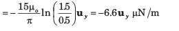
A conducting current strip carrying K = 6uz A/m lies in the x = 0 plane between y = 0.5 and y = 1.5 m. There is also a current filament of I = 5 A in the uz direction on the z –axis.Que: The force exerted on the strip by the filament is- a)- 6.6 uy μN/m
- b)6.6 uy μN/m
- c)2.4uy μN/m
- d)-2.4 uy μN/m
Correct answer is option 'A'. Can you explain this answer?
A conducting current strip carrying K = 6uz A/m lies in the x = 0 plane between y = 0.5 and y = 1.5 m. There is also a current filament of I = 5 A in the uz direction on the z –axis.
Que: The force exerted on the strip by the filament is
a)
- 6.6 uy μN/m
b)
6.6 uy μN/m
c)
2.4uy μN/m
d)
-2.4 uy μN/m
 | Sanchita Pillai answered |

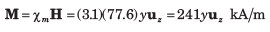
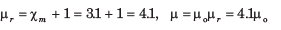
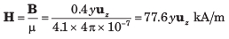
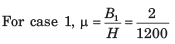
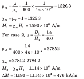
A particular material has 2.7 x 1029 atoms/m3 and each atom has a dipole moment of 2.6 x 1030 uy A .m2. The H in material is (μr = 4.2 )- a)2.94 uy A/m
- b)0.22 uy A/m
- c)0.17 uy A/m
- d)2.24 uy A/m
Correct answer is option 'B'. Can you explain this answer?
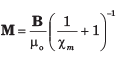
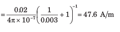
A particular material has 2.7 x 1029 atoms/m3 and each atom has a dipole moment of 2.6 x 1030 uy A .m2. The H in material is (μr = 4.2 )
a)
2.94 uy A/m
b)
0.22 uy A/m
c)
0.17 uy A/m
d)
2.24 uy A/m
| | Siddharth Malhotra answered |
To find the value of H, we need to calculate the magnetic field strength caused by the dipole moments of the atoms in the material.
Given:
Number of atoms per unit volume (n) = 2.7 x 10^29 atoms/m^3
Dipole moment of each atom (p) = 2.6 x 10^30 uA.m^2
Radius of the material (r) = 4.2
- Calculating the magnetic field strength:
The magnetic field strength (H) can be calculated using the formula:
H = (p * n) / (3 * r^3)
Let's calculate step by step:
Step 1: Convert the dipole moment from uA.m^2 to A.m^2:
2.6 x 10^30 uA.m^2 = 2.6 x 10^30 x 10^-6 A.m^2
= 2.6 x 10^24 A.m^2
Step 2: Substitute the values into the formula:
H = (2.6 x 10^24 A.m^2 * 2.7 x 10^29 atoms/m^3) / (3 * (4.2)^3)
Step 3: Simplify the expression:
H = (2.6 x 2.7 x 10^24 x 10^29) / (3 * 4.2^3)
= (7.02 x 10^53) / (3 * 74.088)
= 7.02 x 10^53 / 222.264
= 3.152 x 10^51 A/m
- Comparing with the given options:
The correct answer is option B) 0.22 uA/m.
Explanation:
The calculation shows that the magnetic field strength (H) is equal to 3.152 x 10^51 A/m. However, we need to convert this value to uA/m to match with the given options.
1 A = 10^6 uA
Therefore,
3.152 x 10^51 A/m = 3.152 x 10^51 x 10^6 uA/m
= 3.152 x 10^57 uA/m
Rounding off to two decimal places, we get approximately 0.22 uA/m, which matches with option B) 0.22 uA/m.


Which one of the following laws will not contribute to the Maxwell’s equations?- a)Gauss law
- b)Faraday law
- c)Ampere law
- d)Curie Weiss law
Correct answer is option 'D'. Can you explain this answer?
Which one of the following laws will not contribute to the Maxwell’s equations?
a)
Gauss law
b)
Faraday law
c)
Ampere law
d)
Curie Weiss law
| | Siddharth Khanna answered |
Answer: d
Explanation: The Gauss law, Faraday law and the Ampere law are directly used to find the parameters E, H, D, B. Thus it contributes to the Maxwell equations. The Curie Weiss law pertains to the property of any magnetic material. Thus it is not related to the Maxwell equation.
Explanation: The Gauss law, Faraday law and the Ampere law are directly used to find the parameters E, H, D, B. Thus it contributes to the Maxwell equations. The Curie Weiss law pertains to the property of any magnetic material. Thus it is not related to the Maxwell equation.


The angular separation between the vectors A = 4i + 3j + 5k and B = i – 2j + 2k is (in degrees)- a)65.8
- b)66.8
- c)67.8
- d)68.8
Correct answer is option 'C'. Can you explain this answer?
The angular separation between the vectors A = 4i + 3j + 5k and B = i – 2j + 2k is (in degrees)
a)
65.8
b)
66.8
c)
67.8
d)
68.8
| | Luminary Institute answered |
The dot product the vector is 8. Angle of separation is cos θ = 8/ (7.07 X 3) = 0.377 and θ = cos-1(0.377) = 67.8.
Double stub matching eliminates standing waves on the- a)load side of right stub
- b)source side of the left stub
- c)both sides of the stub
- d)in between the two stubs
Correct answer is option 'B'. Can you explain this answer?
Double stub matching eliminates standing waves on the
a)
load side of right stub
b)
source side of the left stub
c)
both sides of the stub
d)
in between the two stubs
| | Anshika Khanna answered |
Double stub matching eliminates standing waves on the source side of the left stub.
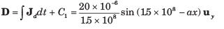
Consider the region defined by |x|,|y| and |z| < 1. Let ε = 5ε0 , μ = 4μo and
σ = 0 the displacement current densityJd = 20cos(1.5 x 10⁸ t - ax)uy μA/m2. Assume no DC fields are present.- a)6sin (1.5 x 10⁸ t - ax) uy mV/m
- b)6cos (1.5 x 10⁸ t - ax) uy mV/m
- c)3cos (1.5 x 10⁸ t - ax) uy mV/m
- d)3sin (1.5 x 10⁸ t - ax) uy mV/m
Correct answer is option 'D'. Can you explain this answer?
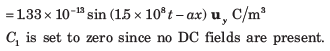
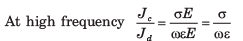
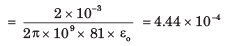
Consider the region defined by |x|,|y| and |z| < 1. Let ε = 5ε0 , μ = 4μo and
σ = 0 the displacement current densityJd = 20cos(1.5 x 10⁸ t - ax)uy μA/m2. Assume no DC fields are present.
a)
6sin (1.5 x 10⁸ t - ax) uy mV/m
b)
6cos (1.5 x 10⁸ t - ax) uy mV/m
c)
3cos (1.5 x 10⁸ t - ax) uy mV/m
d)
3sin (1.5 x 10⁸ t - ax) uy mV/m
 | Saptarshi Nair answered |
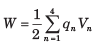
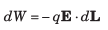
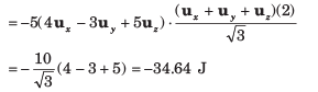
A uniform surface charge density of 30 nC /m2 is present on the spherical surface r = 6 mm in free space. The VAB between A (r = 2 cm, θ = 350 , Ø = 550 ) and B (r = 3 cm, θ = 400 , Ø = 900 )- a)2.03 V
- b)10.17 V
- c)4.07 mV
- d)-10.17 V
Correct answer is option 'D'. Can you explain this answer?
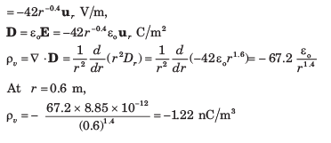
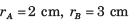
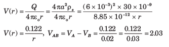
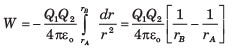
A uniform surface charge density of 30 nC /m2 is present on the spherical surface r = 6 mm in free space. The VAB between A (r = 2 cm, θ = 350 , Ø = 550 ) and B (r = 3 cm, θ = 400 , Ø = 900 )
a)
2.03 V
b)
10.17 V
c)
4.07 mV
d)
-10.17 V
 | Kritika Shah answered |
The gradient of the magnetic vector potential can be expressed as- a)–με dV/dt
- b)+με dE/dt
- c)–με dA/dt
- d)+με dB/dt
Correct answer is option 'A'. Can you explain this answer?
The gradient of the magnetic vector potential can be expressed as
a)
–με dV/dt
b)
+με dE/dt
c)
–με dA/dt
d)
+με dB/dt
| | Arya Mukherjee answered |
Answer: a
Explanation: The gradient of A is the ratio of the negative gradient of electric potential to the speed of light c. We can write c = 1/√(με). Thus grad(A) = -με dV/dt is the required expression.
Explanation: The gradient of A is the ratio of the negative gradient of electric potential to the speed of light c. We can write c = 1/√(με). Thus grad(A) = -με dV/dt is the required expression.

The surface integral of which parameter is zero?- a)E
- b)D
- c)B
- d)H
Correct answer is option 'C'. Can you explain this answer?
The surface integral of which parameter is zero?
a)
E
b)
D
c)
B
d)
H
| | Bibek Saha answered |
Answer: c
Explanation: The divergence of the magnetic flux density is always zero. By Stokes theorem, the surface integral of B is same as the volume integral of the divergence of B. Thus the surface integral of B is also zero.
Explanation: The divergence of the magnetic flux density is always zero. By Stokes theorem, the surface integral of B is same as the volume integral of the divergence of B. Thus the surface integral of B is also zero.

The volume of a parallelepiped in Cartesian is- a)dV = dx dy dz
- b)dV = dx dy
- c)dV = dy dz
- d)dV = dx dz
Correct answer is option 'A'. Can you explain this answer?
The volume of a parallelepiped in Cartesian is
a)
dV = dx dy dz
b)
dV = dx dy
c)
dV = dy dz
d)
dV = dx dz
| | Luminary Institute answered |
The volume of a parallelepiped is given by product of differential length, breadth and height.
The Cartesian coordinates can be related to cylindrical coordinates and spherical coordinates. - a)True
- b)False
- c)Data can not be detemined
- d)None of the above
Correct answer is option 'A'. Can you explain this answer?
The Cartesian coordinates can be related to cylindrical coordinates and spherical coordinates.
a)
True
b)
False
c)
Data can not be detemined
d)
None of the above
| | Luminary Institute answered |
All the coordinate systems are inter-convertible and all the vector operations are applicable to it.
The charge build up in a capacitor is due to- a)Conduction current density
- b)Displacement current density
- c)Polarisation
- d)Magnetization
Correct answer is option 'B'. Can you explain this answer?
The charge build up in a capacitor is due to
a)
Conduction current density
b)
Displacement current density
c)
Polarisation
d)
Magnetization
| | Rounak Rane answered |
Answer: b
Explanation: The capacitor consists of a dielectric placed between two conducting plates, subjected to a field. The current due to a dielectric is always due to the displacement current density.
Explanation: The capacitor consists of a dielectric placed between two conducting plates, subjected to a field. The current due to a dielectric is always due to the displacement current density.
The Cartesian system is also called as- a)Circular coordinate system
- b)Rectangular coordinate system
- c)Spherical coordinate system
- d)Space coordinate system
Correct answer is option 'B'. Can you explain this answer?
The Cartesian system is also called as
a)
Circular coordinate system
b)
Rectangular coordinate system
c)
Spherical coordinate system
d)
Space coordinate system
| | Luminary Institute answered |
The other name for Cartesian is rectangular system, which is given by (x,y,z).
Vector transformation followed by coordinate point substitution and vice-versa, both given the same result. Choose the best answer.- a)Possible, when the vector is constant
- b)Possible, when the vector is variable
- c)Possible in all cases
- d)Not possible
Correct answer is option 'A'. Can you explain this answer?
Vector transformation followed by coordinate point substitution and vice-versa, both given the same result. Choose the best answer.
a)
Possible, when the vector is constant
b)
Possible, when the vector is variable
c)
Possible in all cases
d)
Not possible
| | Luminary Institute answered |
The order of vector transformation and point substitution will not affect the result, only when the vector is a constant.
The propagation of the electromagnetic waves can be illustrated by- a)Faraday law
- b)Ampere law
- c)Flemming rule
- d)Coulomb law
Correct answer is option 'C'. Can you explain this answer?
The propagation of the electromagnetic waves can be illustrated by
a)
Faraday law
b)
Ampere law
c)
Flemming rule
d)
Coulomb law
| | Mainak Roy answered |
Answer: c
Explanation: By Flemming’s rule, when the thumb and the middle finger represent the inputs (say current and field respectively), then the fore finger represents the output (force, in this case). The EM propagation can be illustrated by this rule.
Explanation: By Flemming’s rule, when the thumb and the middle finger represent the inputs (say current and field respectively), then the fore finger represents the output (force, in this case). The EM propagation can be illustrated by this rule.
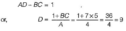
For a reciprocal transmission line, the three transmission parameters are given by A = 4, B = 7 and C = 5. The value of D is equal to- a)8.5
- b)9
- c)-8.5
- d)-9
Correct answer is option 'B'. Can you explain this answer?
For a reciprocal transmission line, the three transmission parameters are given by A = 4, B = 7 and C = 5. The value of D is equal to
a)
8.5
b)
9
c)
-8.5
d)
-9
| | Om Saini answered |
Since the transmission line is reciprocal, therefore,
In a transmission line terminated by characteristic impedance, Z0- a)the incident current is zero for only applied voltage.
- b)there are large number of maximum and minimum on the line.
- c)the reflection is maximum due to termination.
- d)there is no reflection of the incident wave.
Correct answer is option 'D'. Can you explain this answer?
In a transmission line terminated by characteristic impedance, Z0
a)
the incident current is zero for only applied voltage.
b)
there are large number of maximum and minimum on the line.
c)
the reflection is maximum due to termination.
d)
there is no reflection of the incident wave.
| | Sanjana Chopra answered |
When a transmission line is terminated by an impedance Z, then reflection coefficient are:
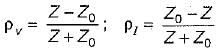
Here, Z0 = Characteristic impedance of transmission line.
Since Z = Z0 therefore reflection co-efficient of voltage (pv) and current (pI) both will be zero, i.e there will be no reflection of incident wave.
Here, Z0 = Characteristic impedance of transmission line.
Since Z = Z0 therefore reflection co-efficient of voltage (pv) and current (pI) both will be zero, i.e there will be no reflection of incident wave.

A rectangular loop of wire in free space joins points A(1, 0, 1) to B(3, 0, 1) to C(3, 0, 4) to D(1, 0, 4) to A. The wire carries a current of 6 mA flowing in the uz direction from B to C. A filamentary current of 15 A flows along the entire z, axis in the uz directions.Que: The total force on the loop is- a)36ux nN
- b)-36ux nN
- c)54ux nN
- d)-54ux nN
Correct answer is option 'A'. Can you explain this answer?
A rectangular loop of wire in free space joins points A(1, 0, 1) to B(3, 0, 1) to C(3, 0, 4) to D(1, 0, 4) to A. The wire carries a current of 6 mA flowing in the uz direction from B to C. A filamentary current of 15 A flows along the entire z, axis in the uz directions.
Que: The total force on the loop is
a)
36ux nN
b)
-36ux nN
c)
54ux nN
d)
-54ux nN
| | Zara Chawla answered |
Given Information:
- Rectangular loop of wire joining points A, B, C, D in free space
- Current of 6 mA flowing from B to C
- Filamentary current of 15 A along z-axis in uz direction
Calculating the Force:
1. Calculate the magnetic field due to the filamentary current along the z-axis at each corner of the loop (A, B, C, D).
2. Using the right-hand rule, determine the direction of the force acting on each segment of the loop due to the magnetic field.
3. Calculate the force on each segment of the loop and then sum up the forces to find the total force on the loop.
Determining the Total Force:
- The force due to the current along the z-axis on segments AB and CD would be in opposite directions, canceling each other out.
- The force on segments BC and DA would add up to give the total force on the loop.
- The total force would be in the direction perpendicular to the loop and can be calculated using the formula F = I * L * B * sin(θ), where I is the current, L is the length of the segment, B is the magnetic field, and θ is the angle between the current and the magnetic field.
Therefore, the total force on the loop is 36 uχ nN in the positive uχ direction.
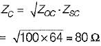
If Zsc = 64Ω and Zoc = 100 Ω, the characteristic impedance will be given by.- a)60 Ω
- b)170 Ω
- c)400 Ω
- d)80 Ω
Correct answer is option 'D'. Can you explain this answer?
If Zsc = 64Ω and Zoc = 100 Ω, the characteristic impedance will be given by.
a)
60 Ω
b)
170 Ω
c)
400 Ω
d)
80 Ω
| | Meghana Gupta answered |
Characteristic impedance is given by
Which of the following statements related to a transmission line is/are correct?
1. Transmission line elements are integral parts of the antenna, in some antenna system.
2. A feeder is a particular case of a transmission Sine.
3. A lossless transmission line doesn’t has resistance but, has a non-zero value of leakage conductance.
4. At radio frequency (RF), R and G both are neglected.- a)1 and 2 only
- b)1, 2 and 4 only
- c)2 and 4 only
- d)1, 2, 3 and 4
Correct answer is option 'B'. Can you explain this answer?
Which of the following statements related to a transmission line is/are correct?
1. Transmission line elements are integral parts of the antenna, in some antenna system.
2. A feeder is a particular case of a transmission Sine.
3. A lossless transmission line doesn’t has resistance but, has a non-zero value of leakage conductance.
4. At radio frequency (RF), R and G both are neglected.
a)
1 and 2 only
b)
1, 2 and 4 only
c)
2 and 4 only
d)
1, 2, 3 and 4
| | Saumya Sen answered |
- Statements-1 and 2 are true.
- Statement-3 is not correct because in a lossless transmission line there is neither resistive loss (i.e. R = 0) nor any leakage current (i.e. G = 0).
- At radio frequency (RF), the inductive reactance is much larger than the resistance and so also the capacitie susceptance in comparison to the shunt conductance. Hence, at radio frequencies R and G both are neglected. Thus, statement-4 is correct.
Chapter doubts & questions for Electromagnetic Fields Theory - 6 Months Preparation for GATE Electrical 2026 is part of Electrical Engineering (EE) exam preparation. The chapters have been prepared according to the Electrical Engineering (EE) exam syllabus. The Chapter doubts & questions, notes, tests & MCQs are made for Electrical Engineering (EE) 2026 Exam. Find important definitions, questions, notes, meanings, examples, exercises, MCQs and online tests here.
Chapter doubts & questions of Electromagnetic Fields Theory - 6 Months Preparation for GATE Electrical in English & Hindi are available as part of Electrical Engineering (EE) exam. Download more important topics, notes, lectures and mock test series for Electrical Engineering (EE) Exam by signing up for free.
6 Months Preparation for GATE Electrical675 videos|1390 docs|885 tests |