


All Exams > Electrical Engineering (EE) > 6 Months Preparation for GATE Electrical > All Questions
All questions of Practice and Mock Tests for Electrical Engineering (EE) Exam
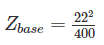
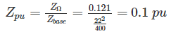
A three phase Y-Δ transformer is rated 400 MVA, 220 kV/22 kV. The short circuit impedance of the transformer measured on low voltage side is 0.121 Ω and because of the low value it is considered equal to the leakage reactance. The per unit value of reactance to represent this transformer in a system whose base on the high voltage side of the transformer is 100 MVA, 230 kV is ___ (pu)- a)2.28 × 10⁻⁴ pu
- b)0.0114 pu
- c)0.0228 pu
- d)1.14 × 10⁻⁴
Correct answer is option 'C'. Can you explain this answer?
A three phase Y-Δ transformer is rated 400 MVA, 220 kV/22 kV. The short circuit impedance of the transformer measured on low voltage side is 0.121 Ω and because of the low value it is considered equal to the leakage reactance. The per unit value of reactance to represent this transformer in a system whose base on the high voltage side of the transformer is 100 MVA, 230 kV is ___ (pu)
a)
2.28 × 10⁻⁴ pu
b)
0.0114 pu
c)
0.0228 pu
d)
1.14 × 10⁻⁴
| | Sanvi Kapoor answered |
On its own base the pu reactance of the transformer is,
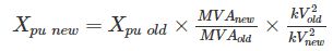
On the chosen base the reactance becomes,


The column vector  (aba) is a simultaneous Eigen vector of
 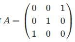 and
and 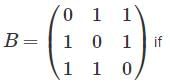
- a)b = 0 or a = 0
- b)b = a or b = -2a
- c)b = 2a or b = -a
- d)b = a/2 or b = -a/2
Correct answer is option 'B'. Can you explain this answer?
The column vector
(aba) is a simultaneous Eigen vector of and a)
b = 0 or a = 0
b)
b = a or b = -2a
c)
b = 2a or b = -a
d)
b = a/2 or b = -a/2
 | Gate Gurus answered |
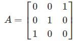
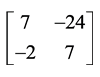
Given that, X =  is an Eigen vector of A.
is an Eigen vector of A.⇒ AX = λ1X
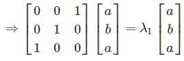
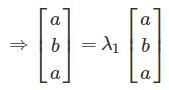
For all values of a and b,  is an Eigen vector of A.
is an Eigen vector of A.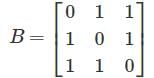
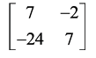
Given that,  is an Eigen vector of B
is an Eigen vector of B⇒ BX = λ2X
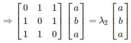
 being an eigen vector of matrix B
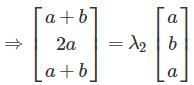
a + b = λ2 a ----(1)
2a = λ2 b ----(2)
From (1) and (2)
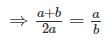
⇒ ab + b2 = 2a2
⇒ 2a2 - ab - b2 = 0
⇒ 2a2 - 2ab + ab - b2 = 0
⇒ 2a (a - b) + b (a - b) = 0
⇒ b = a, b = -2a
For b = a, (or) b = -2a, X is an eigen vector of matrix B.
Consider a circle of radius r. Fit the largest possible square inside it and the largest possible circle inside the square. What is the radius of the innermost circle?- a)

- b)

- c)

- d)r/2
Correct answer is option 'A'. Can you explain this answer?
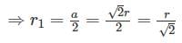
Consider a circle of radius r. Fit the largest possible square inside it and the largest possible circle inside the square. What is the radius of the innermost circle?
a)
b)
c)
d)
r/2
 | Ashwani Mishra answered |
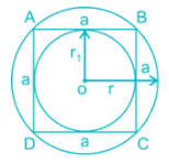
The radius of outer circle = r
∴ Diagonal of square = 2r
Side of square (a) = 
Now, the radius of the inner circle = 
A three phase full converter bridge is connected to supply voltage of 240 V per phase and a frequency of 50 Hz. The source inductance is 5 mH and load current an dc side is constant at 18 A at 30° firing angle. The percentage voltage regulation due to source inductance is _____
Correct answer is '5.2-5.8'. Can you explain this answer?
A three phase full converter bridge is connected to supply voltage of 240 V per phase and a frequency of 50 Hz. The source inductance is 5 mH and load current an dc side is constant at 18 A at 30° firing angle. The percentage voltage regulation due to source inductance is _____
| | Prisha Sen answered |
Voltage at no load = 
Voltage regulation due to source inductance 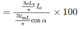
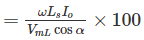
= 5.55 %
A 6 pole slip ring induction motor operating on 50 Hz supply is driven by a variable speed prime mover as a frequency changer. If it is operated at 1500 rpm is opposite direction then the supply frequency generated is – (in Hz)
Correct answer is '125'. Can you explain this answer?
A 6 pole slip ring induction motor operating on 50 Hz supply is driven by a variable speed prime mover as a frequency changer. If it is operated at 1500 rpm is opposite direction then the supply frequency generated is – (in Hz)
| | Arpita Banerjee answered |
25 Hz.
Explanation:
The synchronous speed of a 6 pole induction motor operated on 50 Hz supply is:
Ns = (120 x f) / P = (120 x 50) / 6 = 1000 rpm
Since the motor is driven at 1500 rpm in the opposite direction, the actual speed of the rotor is:
N = Ns - Nr = 1000 - 1500 = -500 rpm
The slip of the motor is given by:
s = (Ns - N) / Ns = (1000 + 500) / 1000 = 1.5
The frequency generated by the slip ring is given by:
f = s x fsupply = 1.5 x 50 = 75 Hz
However, since the motor is operated in the opposite direction, the frequency generated is:
f = fsupply - fslip = 50 - 75 = -25 Hz
Since negative frequency is not physically possible, we take the absolute value:
|f| = 25 Hz
Therefore, the supply frequency generated by the slip ring motor is 25 Hz.
In a group, there are 32 people. All of them know at least one of the three languages : Hindi, English and Marathi. 25 people know Hindi, 20 know English and 15 know Marathi. 15 people know Hindi and English. 5 people know English and Marathi. If 3 people know all the three languages, then how many people know Hindi and Marathi?- a)9
- b)8
- c)13
- d)11
Correct answer is option 'D'. Can you explain this answer?
In a group, there are 32 people. All of them know at least one of the three languages : Hindi, English and Marathi. 25 people know Hindi, 20 know English and 15 know Marathi. 15 people know Hindi and English. 5 people know English and Marathi. If 3 people know all the three languages, then how many people know Hindi and Marathi?
a)
9
b)
8
c)
13
d)
11
| | Mani Paramasivan answered |
Option b is correct
32=(25+20+15)-(15+5+(x+3))+3
32=60-23-x+3
32=40-x
x=8
32=(25+20+15)-(15+5+(x+3))+3
32=60-23-x+3
32=40-x
x=8
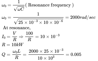
A 10 μF condenser is connected in series with a coil having inductance of 25 mH. If a 100 V source operating at resonance frequency causes a circuit current of 10 mA . What is the Q-factor of the coil?- a)0.5
- b)0.05
- c)0.005
- d)5.0
Correct answer is option 'C'. Can you explain this answer?
A 10 μF condenser is connected in series with a coil having inductance of 25 mH. If a 100 V source operating at resonance frequency causes a circuit current of 10 mA . What is the Q-factor of the coil?
a)
0.5
b)
0.05
c)
0.005
d)
5.0
 | Pioneer Academy answered |
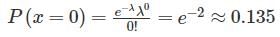
2000 cashew nuts are mixed thoroughly in flour. The entire mixture is divided into 1000 equal parts. And each part is used to make 1 biscuit. Assume that no cashews are broken in the process. A biscuit is picked at random. The probability it contents no cashew is _____.- a)Between 0 and 0.1
- b)Between 0.1 and 0.2
- c)Between 0.2 and 0.3
- d)Between 0.3 and 0.4
Correct answer is option 'B'. Can you explain this answer?
2000 cashew nuts are mixed thoroughly in flour. The entire mixture is divided into 1000 equal parts. And each part is used to make 1 biscuit. Assume that no cashews are broken in the process. A biscuit is picked at random. The probability it contents no cashew is _____.
a)
Between 0 and 0.1
b)
Between 0.1 and 0.2
c)
Between 0.2 and 0.3
d)
Between 0.3 and 0.4
| | Partho Saha answered |
Assuming poisson distribution
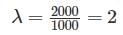
Alternate:
- Probability a particular cashew is in particular biscuit is
- Probability a particular cashew is not in a particular biscuit =
- Probability that no cashew in =
A single-phase transformer is rated 220/440 V,5 kVA, leakage reactance measured from the low-tension side is 0.05Ω . The per unit leakage reactance will be _______.(Give up to four decimal places).
Correct answer is '0.0051'. Can you explain this answer?
A single-phase transformer is rated 220/440 V,5 kVA, leakage reactance measured from the low-tension side is 0.05Ω . The per unit leakage reactance will be _______.
(Give up to four decimal places).
| | Devansh Das answered |
Understanding Per Unit System
In electrical engineering, the per unit system is a method used to normalize system quantities. This allows for easier comparison and calculation across different systems.
Given Data
- Transformer ratings: 220/440 V
- Power rating: 5 kVA
- Leakage reactance (low-tension side): 0.05 Ω
Calculating Base Values
1. Base Voltage on Low-Tension Side (V_base):
- V_base = 220 V
2. Base Power (S_base):
- S_base = 5 kVA = 5000 VA
3. Base Reactance (X_base):
- X_base = V_base^2 / S_base
- X_base = (220 V)² / (5000 VA)
- X_base = 48400 / 5000
- X_base = 9.68 Ω
Calculating Per Unit Leakage Reactance
To find the per unit (pu) leakage reactance:
- Per Unit Reactance (X_pu):
- X_pu = Actual Reactance / Base Reactance
- X_pu = 0.05 Ω / 9.68 Ω
- X_pu = 0.005171
Rounding to Four Decimal Places
- Rounding 0.005171 to four decimal places gives:
- X_pu = 0.0051
Conclusion
The per unit leakage reactance of the transformer is 0.0051. This normalized value simplifies analysis in power systems, allowing engineers to easily compare different transformers and their reactances.
The simplified block diagram of a 10-bit A/D converter of dual slope integrator type is shown in figure. The 10-bit counter at the output is clocked by a 1 MHz clock. Assuming negligible timing overhead for the control logic, the maximum frequency (in kHz) of the analog signal that can be converted using this A/D converter is (Answer up to the nearest integer)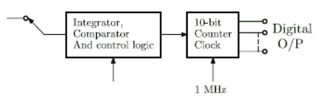
Correct answer is '1'. Can you explain this answer?
The simplified block diagram of a 10-bit A/D converter of dual slope integrator type is shown in figure. The 10-bit counter at the output is clocked by a 1 MHz clock. Assuming negligible timing overhead for the control logic, the maximum frequency (in kHz) of the analog signal that can be converted using this A/D converter is (Answer up to the nearest integer)
| | Pioneer Academy answered |
Maximum frequency of input in dual slop A/D converter is given as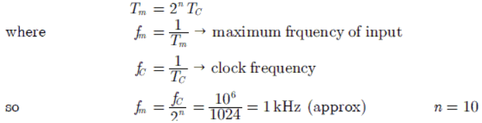
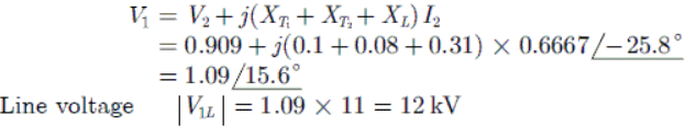
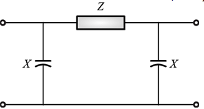
A radial transmission system with the ratings and reactances of the various components is shown in the following figure. A load of 60 MW at 0.9 power factor lagging is fed from the 66 kV substation which is to be maintained at 60 kV. The terminal voltage (line) of the synchronous machine (M) is __________kV. (Answer up to the nearest integer)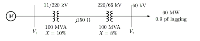
Correct answer is '12'. Can you explain this answer?
A radial transmission system with the ratings and reactances of the various components is shown in the following figure. A load of 60 MW at 0.9 power factor lagging is fed from the 66 kV substation which is to be maintained at 60 kV. The terminal voltage (line) of the synchronous machine (M) is __________kV. (Answer up to the nearest integer)
 | Cstoppers Instructors answered |
Choose 100 MVA base and represent all quantities in pu, we get
Reactance of the first transformer XT1 = 0.1 pu
Reactance of the second transformer XT2 = 0.08 pu
Reactance of transmission line XL = 150 x 100/(200)2 = 0.31 pu
Load in pu 60/100 = 0.6 pu MW;0.9 pf lagging
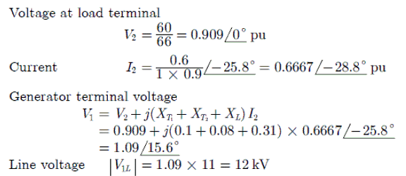
Generator terminal voltage
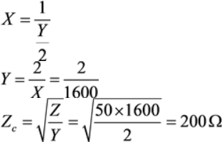
In the figure shown below, a synchronous generator of reactance 0.25 pu feeds the bus-1 and a power network feeds bus-2 of the system. Buses 1 and 2 are connected through a transformer and a transmission line having reactance of 0.12 pu and 0.28 pu respectively.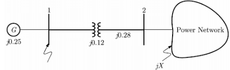 When each bus is at 1.0 pu voltage and generator is on no-load, a three-phase short circuit occurring on bus 1 causes a current of 5 pu to flow into the fault.The equivalent reactance (X in pu) of the power network is ______. (Answer up to one decimal place)
Correct answer is '0.6'. Can you explain this answer?
In the figure shown below, a synchronous generator of reactance 0.25 pu feeds the bus-1 and a power network feeds bus-2 of the system. Buses 1 and 2 are connected through a transformer and a transmission line having reactance of 0.12 pu and 0.28 pu respectively.
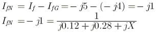
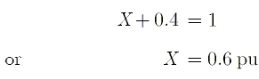
When each bus is at 1.0 pu voltage and generator is on no-load, a three-phase short circuit occurring on bus 1 causes a current of 5 pu to flow into the fault.The equivalent reactance (X in pu) of the power network is ______. (Answer up to one decimal place)
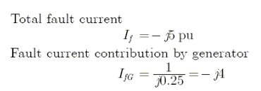
| | Cstoppers Instructors answered |
Fault current contribution by power network
We know that
Consider the following synchronous counter made up of JK, D and T Flip-Flops. The modulus value of the counter is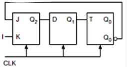 Correct answer is '5'. Can you explain this answer?
Consider the following synchronous counter made up of JK, D and T Flip-Flops. The modulus value of the counter is
| | Sarita Yadav answered |
Consider characteristic equation of 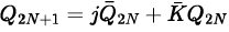 here
here
here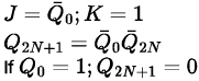
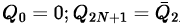 Consider characteristic equation of D− Flip-Flop.
(ii) Consider characteristic equation of T - Flip-Flop Consider charactrisic

Using equations (i), (ii) and (iii)
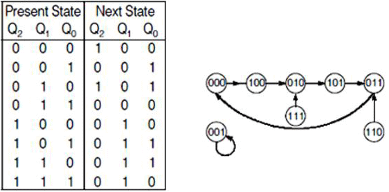
The number of used states = 5
∴ Modulus value = 5
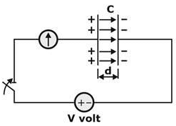
In the given figure, a V volt Battery is connected across the capacitor, galvanometer shows the deflection of found. The switch is closed at t = 0. If distance between the plate of capacitor is increased after which the switch is removed from the circuit. What will be effect on Vc capacitor voltage & electric field .
.
- a)Vc increased,
 remain same
 - b)Vc decreased,
 remain same
 - c)Vc &
 Both are increased
 - d)Vc &
 Both are decreased
Correct answer is option 'A'. Can you explain this answer?
In the given figure, a V volt Battery is connected across the capacitor, galvanometer shows the deflection of found. The switch is closed at t = 0. If distance between the plate of capacitor is increased after which the switch is removed from the circuit. What will be effect on Vc capacitor voltage & electric field .
.a)
Vc increased, remain same
remain sameb)
Vc decreased, remain same
remain samec)
Vc & Both are increased
Both are increasedd)
Vc & Both are decreased
Both are decreased| | Ravi Singh answered |
When the switch is closed for a long line then capacitor will charges up to Vc = V volt.
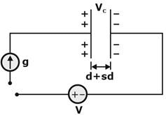
Now as the switch is removed as shown in figure.
The charge Q across the plate of capacitor are trapped.
After removing the switch distance between the plate of capacitor to increased.
 therefore C w ill decrease.
 as the charge are trapped i.e; constant.
So  where VC is decreased therefore Vc will increases.
where VC is decreased therefore Vc will increases.So, E remain constant.
A DC-DC converter is used to feed the resistive load and its output is always inverted. An alternating square wave voltage is getting produced across in inductor having rms value of 200 V and frequency of 50 Hz. the duty cycle of the switch is______
Correct answer is '0.5'. Can you explain this answer?
A DC-DC converter is used to feed the resistive load and its output is always inverted. An alternating square wave voltage is getting produced across in inductor having rms value of 200 V and frequency of 50 Hz. the duty cycle of the switch is______
| | Sanskriti Kaur answered |
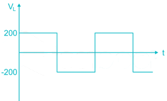
Given circuit is Buck Boost converter
Voltage across inductor would be, Vs = 200 V
Vo = 200 V
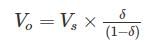
⇒ δ = 1 – δ
⇒ δ = 0.5
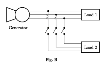
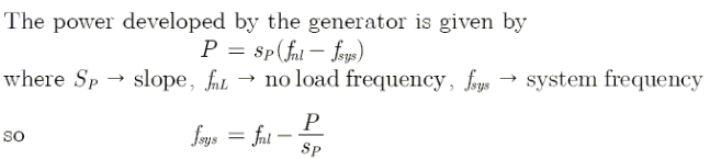
A generator with the frequency-power characteristics shown in figure A is supplying a load. Now a second load is to be connected in parallel with the first one as shown in figure B. Load 1 consumes a real power of 1000 kW at 0.8 PF lagging, while load 2 consumes a real power of 800 kW at 0.707 PF lagging. The operating frequencies of the system before and after the second load is connected are respectively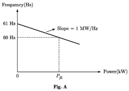
- a)60 Hz, 61 Hz
- b)61 Hz, 60 Hz
- c)60 Hz, 60 Hz
- d)60 Hz, 59.2 Hz
Correct answer is option 'D'. Can you explain this answer?
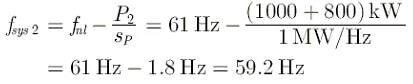
A generator with the frequency-power characteristics shown in figure A is supplying a load. Now a second load is to be connected in parallel with the first one as shown in figure B. Load 1 consumes a real power of 1000 kW at 0.8 PF lagging, while load 2 consumes a real power of 800 kW at 0.707 PF lagging. The operating frequencies of the system before and after the second load is connected are respectively
a)
60 Hz, 61 Hz
b)
61 Hz, 60 Hz
c)
60 Hz, 60 Hz
d)
60 Hz, 59.2 Hz
| | Pooja Patel answered |
After the second load is connected,
Before the second load is connected system frequency is
The integrating factor of equation y log y dx + (x – log y) dy = 0 is- a)log x
- b)log y
- c)log (log x)
- d)log (log y)
Correct answer is option 'B'. Can you explain this answer?
The integrating factor of equation y log y dx + (x – log y) dy = 0 is
a)
log x
b)
log y
c)
log (log x)
d)
log (log y)
| | Mainak Pillai answered |
Understanding the Given Differential Equation
The equation provided is:
y log y dx + (x – log y) dy = 0
This is a first-order differential equation that can be analyzed for an integrating factor.
Identifying the Components
To find the integrating factor, we rewrite the equation in the standard form:
M(x, y) = y log y,
N(x, y) = x - log y.
Here, M and N are functions of x and y.
Calculating the Partial Derivatives
Next, we calculate the partial derivatives:
- ∂M/∂y = log y + 1
- ∂N/∂x = 1
We check for exactness:
- If ∂M/∂y ≠ ∂N/∂x, the equation is not exact.
Since log y + 1 ≠ 1, the equation is not exact.
Finding the Integrating Factor
For the equation to become exact, we seek an integrating factor that depends solely on y. The integrating factor is typically of the form µ(y).
The ratio of the differences of the partial derivatives gives us a clue:
µ(y) = (∂N/∂x) / (∂M/∂y - ∂N/∂x)
Substituting the values:
µ(y) = 1 / (log y + 1 - 1) = 1 / log y
Thus, the integrating factor simplifies to:
µ(y) = log y
Conclusion
The integrating factor for the given differential equation is indeed log y, confirming that option 'B' is the correct answer. This factor can be used to multiply the entire equation, making it exact and solvable.
It is desired to measure the parameters of 230V/115V, 2kVA, single phase transformer. The following wattmeters are available in a laboratory.W1: 250 V, 10 A, Low Power FactorW2: 250 V, 5 A, Low Power FactorW3: 150 V, 10 A, High Power FactorW4: 150 V, 5 A, High Power FactorThe wattmeters used in open circuit test and short circuit test of the transformer will respectively be- a)W1 and W2
- b)W2and W4
- c)W1 and W4
- d)W2 and W3
Correct answer is option 'D'. Can you explain this answer?
It is desired to measure the parameters of 230V/115V, 2kVA, single phase transformer. The following wattmeters are available in a laboratory.
W1: 250 V, 10 A, Low Power Factor
W2: 250 V, 5 A, Low Power Factor
W3: 150 V, 10 A, High Power Factor
W4: 150 V, 5 A, High Power Factor
The wattmeters used in open circuit test and short circuit test of the transformer will respectively be
a)
W1 and W2
b)
W2and W4
c)
W1 and W4
d)
W2 and W3
| | Pankaj Mehta answered |
Measurement of Transformer Parameters Using Wattmeters
Open Circuit Test:
- Wattmeter W2 and W3 are not suitable as they have low power factor and high power factor respectively which will not give accurate readings for open circuit test.
- Wattmeter W1 can be used as it can measure up to 250V and 10A, which is suitable for measuring the voltage and current of the high voltage winding of the transformer during open circuit test.
- Wattmeter W4 can also be used as it can measure up to 150V and 5A, which is suitable for measuring the voltage and current of the low voltage winding of the transformer during open circuit test.
- Therefore, the wattmeters used in open circuit test of the transformer will be W1 and W4.
Short Circuit Test:
- Wattmeter W1 is not suitable for short circuit test as it can measure up to 250V and 10A, which is too high for measuring the voltage and current of the low voltage winding of the transformer during short circuit test.
- Wattmeter W4 is also not suitable for short circuit test as it can measure up to 150V and 5A, which is too low for measuring the voltage and current of the high voltage winding of the transformer during short circuit test.
- Wattmeter W2 can be used as it can measure up to 250V and 5A, which is suitable for measuring the voltage and current of the high voltage winding of the transformer during short circuit test.
- Wattmeter W3 can also be used as it can measure up to 150V and 10A, which is suitable for measuring the voltage and current of the low voltage winding of the transformer during short circuit test.
- Therefore, the wattmeters used in short circuit test of the transformer will be W2 and W3.
Conclusion:
- The suitable wattmeters for open circuit test of the transformer are W1 and W4, while the suitable wattmeters for short circuit test of the transformer are W2 and W3.
- Therefore, the correct answer is option D.
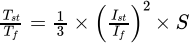
What is the ratio of starting torque(Tst) to full load torque(Tfl) when an induction motor is started using auto transformer and it has a full load slip(Sfl) of 0.02. Its starting current(Ist) is 3 times its full load current(Ifl)?- a)0.6
- b)0.06
Correct answer is between '0.6,0.06'. Can you explain this answer?
What is the ratio of starting torque(Tst) to full load torque(Tfl) when an induction motor is started using auto transformer and it has a full load slip(Sfl) of 0.02. Its starting current(Ist) is 3 times its full load current(Ifl)?
a)
0.6
b)
0.06
| | Yash Patel answered |

Given the following state table of an FSM with two states A and B, one input and one output: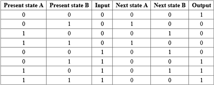 If the initial state is A = 0, B = 0, the minimum length of an input string which will take the machine to the state A = 0, B = 1 with Output = 1
- a)3
- b)4
- c)5
- d)6
Correct answer is option 'A'. Can you explain this answer?
Given the following state table of an FSM with two states A and B, one input and one output:
If the initial state is A = 0, B = 0, the minimum length of an input string which will take the machine to the state A = 0, B = 1 with Output = 1
a)
3
b)
4
c)
5
d)
6
| | Pioneer Academy answered |
From given state table easily form the state diagram in step by step manner as,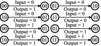
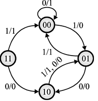
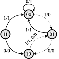
So, combined all above state diagram to get single compact state diagram as,
So, minimum length of input string start from A=0, B=0 to A=0 ,B=1 with output = 1 is shown below by dotted lines as,
So, input string length ⇒101 ⇒ 3-bit.
At an industrial substation with a 8 MW load,a capacitor of 4 MVAR is installed to maintain load pf at 0.9 leading if a compensating element is also connected so that pf changes to 0.9 lagging, the compensating element is- a)Capacitor of 4.5 MVAR
- b)Inductor of 4.5 MVAR
- c)Capacitor of 7.75 MVAR
- d)Inductor of 7.75 MVAR
Correct answer is option 'D'. Can you explain this answer?
At an industrial substation with a 8 MW load,a capacitor of 4 MVAR is installed to maintain load pf at 0.9 leading if a compensating element is also connected so that pf changes to 0.9 lagging, the compensating element is
a)
Capacitor of 4.5 MVAR
b)
Inductor of 4.5 MVAR
c)
Capacitor of 7.75 MVAR
d)
Inductor of 7.75 MVAR
| | Zoya Sharma answered |
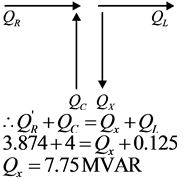
Previously the substation was working on 0.9 leading.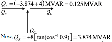
Given: PL = Load power = 8 MW
QC = 4MVAR
pf = 0.9 leading
Receiving end power = PR = PL = 8 MW
∴ Receiving end reactive power = QR = -8tan [cos-10.9]
QR = -8tan [cos-1(0.9)]MVAR = -3.874MVAR
∴ Load reactive power, QL = QR + QC
Let,the element receives a reactive power of Qx ,
As the element absorbs lagging reactive power so element is an inductor of 7.75 MVAR.
Substation is supplying a load which consumes a complex power of 50+j50 MVA. A reactive power controlled capacitor bank is connected across load with a range of 0≤QC≤40MVAr . This QC controller adopts step wise control with each step of 5 MVAr. To improve overall power factor close to 0.9 lag, the number of steps connected will be________. (by considering step number ‘0’ for Qc = 0MVAr )- a)5
- b)6
- c)7
- d)8
Correct answer is option 'A'. Can you explain this answer?
Substation is supplying a load which consumes a complex power of 50+j50 MVA. A reactive power controlled capacitor bank is connected across load with a range of 0≤QC≤40MVAr . This QC controller adopts step wise control with each step of 5 MVAr. To improve overall power factor close to 0.9 lag, the number of steps connected will be________. (by considering step number ‘0’ for Qc = 0MVAr )
a)
5
b)
6
c)
7
d)
8
| | Zoya Sharma answered |
Given
Complex power = 50 + j50MVA
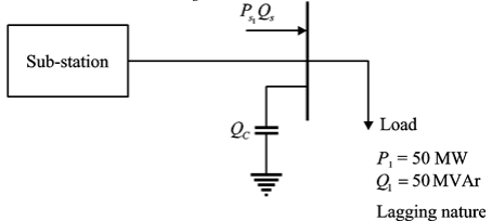
Assume that C-bank injecting Qc amount of reactive power.
Let number of steps = n
So, Qc = 5nMVAr )
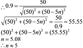
Now real and reactive power supplied by source Ps = 50MW
Qs = Q1-Qc = 50 - 5n
Overall power factor, 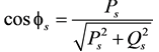
It is given that
Two 3-phase, Y-connected alternators are to be paralleled to a set of common busbars. The armature has a per phase synchronous reactance of 1.7Ω and negligible armature resistance. The line voltage of the first machine is adjusted to 3,300 V and that of the second machine is adjusted to 3,200 V. The machine voltages are in phase at the instant they are paralleled. Under this condition, the synchronising current per phase (in A) will be (Answer up to two decimal places)
Correct answer is '16.98'. Can you explain this answer?
Two 3-phase, Y-connected alternators are to be paralleled to a set of common busbars. The armature has a per phase synchronous reactance of 1.7Ω and negligible armature resistance. The line voltage of the first machine is adjusted to 3,300 V and that of the second machine is adjusted to 3,200 V. The machine voltages are in phase at the instant they are paralleled. Under this condition, the synchronising current per phase (in A) will be (Answer up to two decimal places)
| | Pooja Patel answered |
Given that the armature has per phase synchronous reactance of 1.7Ω and two alternators are connected in parallel.
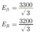
So,
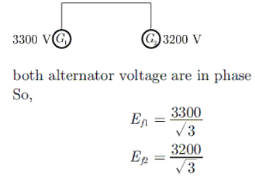
Both alternator voltage are in phase
So,
Synchronizing current or circulating current
Reactance of both alternator are same
So,
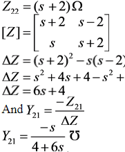
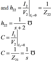
Consider the two port network shown in figure below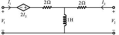 Which of the following is (are) correct?
- a)The value of Z-parameter Z11=s+2Ω
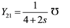
- b)The value of Y-parameter
- c)The value of transmission parameter
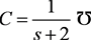
- d)The value of hybrid parameter
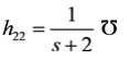
Correct answer is option 'A AND D'. Can you explain this answer?
Consider the two port network shown in figure below
Which of the following is (are) correct?
a)
The value of Z-parameter Z11=s+2Ω
b)
The value of Y-parameter
c)
The value of transmission parameter
d)
The value of hybrid parameter
| | Cstoppers Instructors answered |
Given circuit in s-domain is
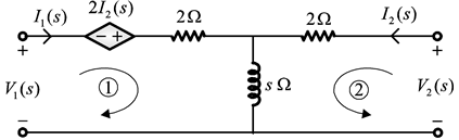
Applying KVL in loop (1)
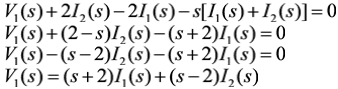
Comparing with V1 = Z11I1 + Z12I2
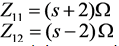
Applying KVL in loop (2)
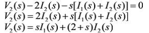
Comparing with V2 = Z21I1 + Z22I2
Z21 = sΩ
The rectification efficiency of a single phase Half Wave Controlled Rectifier having a resistive load and the delay angle of π/2 is _______%. (correct upto two decimal places
Correct answer is '20.23'. Can you explain this answer?
The rectification efficiency of a single phase Half Wave Controlled Rectifier having a resistive load and the delay angle of π/2 is _______%. (correct upto two decimal places
| | Naveen Mukherjee answered |
The rectification efficiency of a single-phase half-wave controlled rectifier can be calculated using the following formula:
η = (Vdc / Vac) × 100
Where:
η is the rectification efficiency
Vdc is the DC output voltage
Vac is the AC input voltage
In a half-wave controlled rectifier, the output voltage is given by the equation:
Vdc = (2 / π) * Vac * (1 - cos(α))
Where:
α is the delay angle
To calculate the rectification efficiency, we need to substitute the values into the equations and solve for η.
Given:
Delay angle (α) = π/2
1. Calculate the DC output voltage (Vdc):
Vdc = (2 / π) * Vac * (1 - cos(π/2))
= (2 / π) * Vac * (1 - 0)
= (2 / π) * Vac
2. Calculate the rectification efficiency (η):
η = (Vdc / Vac) × 100
= [(2 / π) * Vac / Vac] × 100
= (2 / π) × 100
≈ 20.23%
Therefore, the rectification efficiency of the single-phase half-wave controlled rectifier with a resistive load and a delay angle of π/2 is approximately 20.23%.
Note: The rectification efficiency represents the percentage of AC power converted into DC power. In this case, since we are using a half-wave rectifier, only half of the AC input waveform is utilized, resulting in a lower rectification efficiency compared to full-wave rectifiers. The delay angle determines the point in the AC cycle at which the rectifier starts conducting, and a delay angle of π/2 means the rectifier conducts from the peak of the AC waveform.
η = (Vdc / Vac) × 100
Where:
η is the rectification efficiency
Vdc is the DC output voltage
Vac is the AC input voltage
In a half-wave controlled rectifier, the output voltage is given by the equation:
Vdc = (2 / π) * Vac * (1 - cos(α))
Where:
α is the delay angle
To calculate the rectification efficiency, we need to substitute the values into the equations and solve for η.
Given:
Delay angle (α) = π/2
1. Calculate the DC output voltage (Vdc):
Vdc = (2 / π) * Vac * (1 - cos(π/2))
= (2 / π) * Vac * (1 - 0)
= (2 / π) * Vac
2. Calculate the rectification efficiency (η):
η = (Vdc / Vac) × 100
= [(2 / π) * Vac / Vac] × 100
= (2 / π) × 100
≈ 20.23%
Therefore, the rectification efficiency of the single-phase half-wave controlled rectifier with a resistive load and a delay angle of π/2 is approximately 20.23%.
Note: The rectification efficiency represents the percentage of AC power converted into DC power. In this case, since we are using a half-wave rectifier, only half of the AC input waveform is utilized, resulting in a lower rectification efficiency compared to full-wave rectifiers. The delay angle determines the point in the AC cycle at which the rectifier starts conducting, and a delay angle of π/2 means the rectifier conducts from the peak of the AC waveform.
Read the argument given below and then answer the questions which follow the argument.Canada’s commercial seal “hunt” is the largest mass slaughter of marine mammals in the world. This year, Canada will allow 270,000 harp seals to be killed. Canada’s 2006 quota for killing seals: 325,000 for the regular commercial “hunt” and an additional 10,000 harp seal allowance for new aboriginal initiatives, personal use, and Arctic hunts. As usual, the commercial quota was exceeded, resulting in over 330,000 seals being killed. During the previous three years, the government of Canada delivered the death sentence to over one million baby harp seals.The above statement assumes that- a)There is a need to clear off the excessive number of seals in Canada.
- b)The seals are a source of income for the Canadian government.
- c)The slaughter of seals is incredibly cruel.
- d)The excessive killings are usually punishable by law.
Correct answer is option 'B'. Can you explain this answer?
Read the argument given below and then answer the questions which follow the argument.
Canada’s commercial seal “hunt” is the largest mass slaughter of marine mammals in the world. This year, Canada will allow 270,000 harp seals to be killed. Canada’s 2006 quota for killing seals: 325,000 for the regular commercial “hunt” and an additional 10,000 harp seal allowance for new aboriginal initiatives, personal use, and Arctic hunts. As usual, the commercial quota was exceeded, resulting in over 330,000 seals being killed. During the previous three years, the government of Canada delivered the death sentence to over one million baby harp seals.
The above statement assumes that
a)
There is a need to clear off the excessive number of seals in Canada.
b)
The seals are a source of income for the Canadian government.
c)
The slaughter of seals is incredibly cruel.
d)
The excessive killings are usually punishable by law.
| | Saranya Dey answered |
Understanding the Argument
The argument presented highlights the extensive seal hunting in Canada, emphasizing the scale of the slaughter and its implications. Among the assumptions made, option 'B' is considered correct.
Key Points Supporting Option 'B'
- Economic Motivation: The argument implies that seal hunting is a significant commercial activity, suggesting that seals serve as a source of income for those involved in the hunt.
- Commercial Quotas: The mention of specific quotas for hunting indicates that the government recognizes the commercial value of seal hunting, reinforcing the idea that it contributes to the economy.
- Government Oversight: The existence of quotas and the regulation of seal hunting imply that the government is actively involved in managing this practice for economic benefit.
Why Other Options are Less Relevant
- Need to Control Population (Option A): While there may be discussions about seal population control, the argument does not explicitly state that there is an excessive number of seals needing removal for ecological reasons.
- Cruelty of the Slaughter (Option C): Although the argument suggests that the slaughter is massive and implies cruelty, it does not make a direct assumption about the inherent cruelty being a primary reason for the hunt.
- Legality of Killings (Option D): The argument mentions exceeded quotas but does not indicate that these excessive killings are punishable by law, making this assumption unsupported.
Conclusion
In summary, option 'B' stands out as it directly relates to the economic aspects of seal hunting, which is a central theme in the argument. The other options lack explicit support or relevance to the core message.
From Set A = {2, 3, 4, 5} and Set B = {11, 12, 13, 14, 15}, two numbers are randomly selected, one from each set. The probability that the sum of the two numbers equals 16 is ___. (Answer up to one decimal place)
Correct answer is '0.2'. Can you explain this answer?
From Set A = {2, 3, 4, 5} and Set B = {11, 12, 13, 14, 15}, two numbers are randomly selected, one from each set. The probability that the sum of the two numbers equals 16 is ___. (Answer up to one decimal place)
| | Pooja Patel answered |
Set A = {2, 3, 4, 5}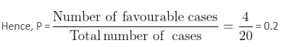
Set B = {11, 12, 13, 14, 15}
Two numbers are chosen, one from set A and other from set B.
Then,
Total = 4 × 5 = 20 cases
Favourable case: Sum of two numbers equals 16.
{(5, 11), (4, 12), (3, 13), (2, 14)}
i.e. Number of favourable cases = 4
In the question given below there are three statements followed by three conclusions. You have to read the given three statements and take them to be true even if they seem to be at variance from commonly known facts. Read the conclusions and then decide which of the conclusions logically follows from the given three statements, disregarding commonly known facts.Statements :(i) All airports are tidy.(ii) Some departments are neat.(iii) Some airports are departments.Conclusions :(i) Some departments are tidy.(ii) Some airports are neat.(iii) No neat is airport.- a)Only (i) follows
- b)Only (ii) follows
- c)(i) and either (ii) or (iii) follow
- d)All follow
Correct answer is option 'C'. Can you explain this answer?
In the question given below there are three statements followed by three conclusions. You have to read the given three statements and take them to be true even if they seem to be at variance from commonly known facts. Read the conclusions and then decide which of the conclusions logically follows from the given three statements, disregarding commonly known facts.
Statements :
(i) All airports are tidy.
(ii) Some departments are neat.
(iii) Some airports are departments.
Conclusions :
(i) Some departments are tidy.
(ii) Some airports are neat.
(iii) No neat is airport.
a)
Only (i) follows
b)
Only (ii) follows
c)
(i) and either (ii) or (iii) follow
d)
All follow
| | Arnav Sharma answered |
Understanding the Statements
To analyze the conclusions, let's break down the statements:
- Statement (i): All airports are tidy.
- Statement (ii): Some departments are neat.
- Statement (iii): Some airports are departments.
Analyzing the Conclusions
Now, let's evaluate each conclusion:
- Conclusion (i): Some departments are tidy.
- Given that all airports are tidy and some airports are departments, it logically follows that some departments must be tidy. Thus, this conclusion is valid.
- Conclusion (ii): Some airports are neat.
- Since some departments are neat and some airports are departments, it can be inferred that at least some airports are neat. Therefore, this conclusion also holds true.
- Conclusion (iii): No neat is airport.
- This conclusion is not supported by the statements. The statements do not provide any basis for assuming that neat departments cannot be airports. Thus, this conclusion does not follow.
Final Evaluation
Considering the evaluations:
- Conclusion (i) is true.
- Conclusion (ii) is true.
- Conclusion (iii) is false.
Therefore, the correct option is (c): (i) and either (ii) or (iii) follow. Since both (i) and (ii) are valid while (iii) is not, option (c) is indeed the right answer.
This logical deduction showcases the importance of carefully analyzing premises to derive valid conclusions.
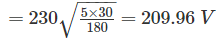
A single phase full bridge inverter controls the power in a resistance load. The nominal value of input dc voltage is Vdc = 230 V and a uniform pulse width modulation with five pulses per half cycle is used for the required control the width of each pulse is 30°, if the dc supply increased by 20%, then the pulse width (in degrees) to maintain the same load power is _____
Correct answer is between '20,22'. Can you explain this answer?
A single phase full bridge inverter controls the power in a resistance load. The nominal value of input dc voltage is Vdc = 230 V and a uniform pulse width modulation with five pulses per half cycle is used for the required control the width of each pulse is 30°, if the dc supply increased by 20%, then the pulse width (in degrees) to maintain the same load power is _____
| | Juhi Joshi answered |
Given that, input dc voltage Vdc = 230 V
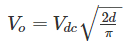
After increase in the dc supply
Vdc = 1.2 × 230 = 276 V
to maintain the same load power.
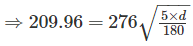
⇒ d = 20.83°
The number of triangles that can be formed by joining the vertices of a heptagon is- a)49
- b)35
- c)71
- d)25
Correct answer is option 'B'. Can you explain this answer?
The number of triangles that can be formed by joining the vertices of a heptagon is
a)
49
b)
35
c)
71
d)
25
| | Mainak Roy answered |
Number of Triangles in a Heptagon
To find the number of triangles that can be formed by joining the vertices of a heptagon, let's break down the problem step by step.
Step 1: Understanding a Heptagon
A heptagon is a polygon with seven sides and seven vertices. Each vertex can be connected to any other vertex to form a triangle.
Step 2: Counting Triangles
To count the number of triangles, we need to consider the possible combinations of three vertices chosen from the seven available vertices.
Step 3: Applying Combinations
To calculate the number of combinations, we can use the formula for combinations:
C(n, r) = n! / (r!(n-r)!)
Where n is the total number of items, and r is the number of items chosen at a time.
In this case, n = 7 (number of vertices) and r = 3 (number of vertices needed to form a triangle).
C(7, 3) = 7! / (3!(7-3)!)
= 7! / (3!4!)
= (7 * 6 * 5 * 4!) / (3 * 2 * 1 * 4!)
= (7 * 6 * 5) / (3 * 2 * 1)
= 35
Therefore, the number of triangles that can be formed by joining the vertices of a heptagon is 35.
Answer: Option B (35)
Which of the following is the antonym of the word SILENCE?- a)Attune
- b)Babble
- c)Achromatic
- d)Aurora
Correct answer is option 'B'. Can you explain this answer?
Which of the following is the antonym of the word SILENCE?
a)
Attune
b)
Babble
c)
Achromatic
d)
Aurora
| | Pooja Patel answered |
Silence refers to 'no speech'. Babble means continuous, and sometimes incoherent speech.
A speaks the truth in 70% cases and B in 80% cases. The probability that they willcontradict each other in describing a single event is- a)0.36
- b)0.38
- c)0.62
- d)0.42
Correct answer is option 'B'. Can you explain this answer?
A speaks the truth in 70% cases and B in 80% cases. The probability that they will
contradict each other in describing a single event is
a)
0.36
b)
0.38
c)
0.62
d)
0.42
| | Pooja Patel answered |
Probability that A and B will contradict each other is that A speaks truth and B lies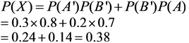
and B speaks truth. Let the probability be P(x). Probability of A speaking truth is P(A) and probability of B speaking truth isP(B)
The following sentence has been divided into four parts indicated by a number. One of the parts contains a usage or grammar error. Mark that number indicating that part of the sentence as your answer.Those who want to develop (A)/the rainforests have played (B)/down the impact of (C)/ his human inhabitants.(D)- a)Those who want to develop
- b)the rainforests have played
- c)the rainforests have played
- d)his human inhabitants.
Correct answer is option 'D'. Can you explain this answer?
The following sentence has been divided into four parts indicated by a number. One of the parts contains a usage or grammar error. Mark that number indicating that part of the sentence as your answer.
Those who want to develop (A)/the rainforests have played (B)/down the impact of (C)/ his human inhabitants.(D)
a)
Those who want to develop
b)
the rainforests have played
c)
the rainforests have played
d)
his human inhabitants.
| | Yash Patel answered |
Pronoun inconsistency.The pronoun should be ‘their’ instead of ‘his’ as it refers to rainforests.So, option (D) should be corrected.
Select the most appropriate word to fill in the blank.Many items made of ivory were _____ from a dealer in antiques by the custom authorities at the Delhi airport.- a)confiscated
- b)hijacked
- c)annexed
- d)appropriated
Correct answer is option 'A'. Can you explain this answer?
Select the most appropriate word to fill in the blank.
Many items made of ivory were _____ from a dealer in antiques by the custom authorities at the Delhi airport.
a)
confiscated
b)
hijacked
c)
annexed
d)
appropriated
| | Yash Patel answered |
The sentence implies that the custom authorities seized many items made of ivory.
‘Confiscate’ means ‘take or seize (someone's property) with authority’. This word fits best in the sentence.
Therefore, option A is the correct answer.
In the circuit of figure, Vs = 2 cos3t volts the VL(t) will be-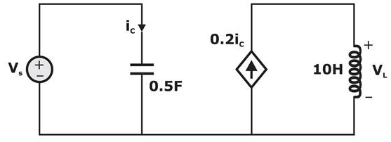
- a)6cos3t volts
- b)-6sin3t volts
- c)18sin3t volts
- d)–18cos3t volts
Correct answer is option 'D'. Can you explain this answer?
In the circuit of figure, Vs = 2 cos3t volts the VL(t) will be-
a)
6cos3t volts
b)
-6sin3t volts
c)
18sin3t volts
d)
–18cos3t volts
| | Cstoppers Instructors answered |
Current across capacitor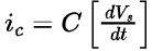
Where,
V0 = [2 cos 3f] volts
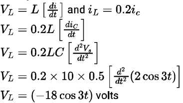
Voltage across inductor
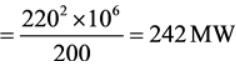
In a 132 kV system, the series inductance up to the point of circuit breaker location is 50 mH. The shunt capacitance at the circuit breaker terminal is 0.05 μF. The critical value of resistance in ohms required to be connected across the circuit breaker contacts which will give no transient oscillation is _____________.Correct answer is '500'. Can you explain this answer?
In a 132 kV system, the series inductance up to the point of circuit breaker location is 50 mH. The shunt capacitance at the circuit breaker terminal is 0.05 μF. The critical value of resistance in ohms required to be connected across the circuit breaker contacts which will give no transient oscillation is _____________.
| | Sanvi Kapoor answered |
Given data L = 50 mH, C = 0.05 μF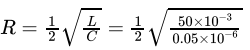
Critical resistance to have transient free oscillations is
R = 500 Ω
Consider the two port network shown in figure below,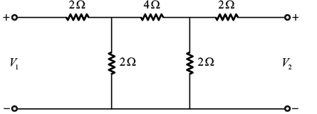 The transmission parameter matrix is,
- a)

- b)
- c)
- d)

Correct answer is option 'A'. Can you explain this answer?
Consider the two port network shown in figure below,
The transmission parameter matrix is,
a)
b)
c)
d)
| | Cstoppers Instructors answered |
Given circuit is shown below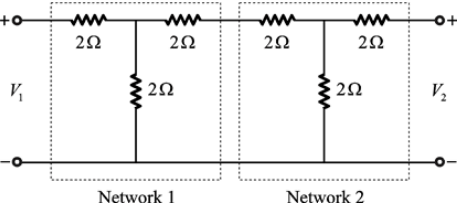
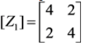
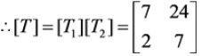
For network 1, that is T-network
The Z-parameter matrix is,
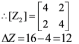
Similarly for network 2, that the Z-parameters matrix is [Z2]
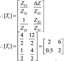
From the relationship between Z-parameters and T-parameters,
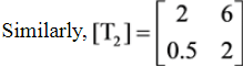
For the cascade connection, the overall T-parameters is the product of T-parameters of the individual networks,
If Rolle's theorem holds for f(x) = x3 − 6x2 + kx + 5 on [1, 3] with c = +1/3 , then the value of k is _____.(Answer up to the nearest integer)Correct answer is '11'. Can you explain this answer?
If Rolle's theorem holds for f(x) = x3 − 6x2 + kx + 5 on [1, 3] with c = +1/3 , then the value of k is _____.(Answer up to the nearest integer)
| | Prisha Kulkarni answered |
Understanding Rolle's Theorem
Rolle's Theorem states that if a function is continuous on a closed interval [a, b], differentiable on the open interval (a, b), and f(a) = f(b), then there exists at least one c in (a, b) such that f'(c) = 0.
Function Details
For the given function f(x) = x³ - 6x² + kx + 5:
- Interval: [1, 3]
- c: Given as +1/3
Step 1: Check Continuity and Differentiability
- The function is a polynomial, thus continuous and differentiable everywhere, including the interval [1, 3].
Step 2: Calculate f(1) and f(3)
- f(1):
f(1) = 1³ - 6(1)² + k(1) + 5 = 1 - 6 + k + 5 = k
- f(3):
f(3) = 3³ - 6(3)² + k(3) + 5 = 27 - 54 + 3k + 5 = 3k - 22
Step 3: Set f(1) = f(3)
To satisfy Rolle's theorem:
- k = 3k - 22
Rearranging gives:
- 22 = 2k
- k = 11
Conclusion
Thus, the value of k, satisfying the conditions of Rolle's theorem for the function on the interval [1, 3] is:
- k = 11
This aligns with the correct answer provided.
For the waveform shown in the figure, which equation correctly represents it?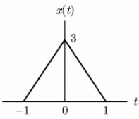
- a)3(t + 1)u(t + 1) − 3tu(t − 1) + 6u(t − 1)
- b)3(t + 1)u(t + 1) − 6tu(t) + 3(t − 1)u(t − 1)
- c)3(t + 1)u(t + 1) − 3(t − 1)u(t − 1)
- d)None of these
Correct answer is option 'B'. Can you explain this answer?
a)
3(t + 1)u(t + 1) − 3tu(t − 1) + 6u(t − 1)
b)
3(t + 1)u(t + 1) − 6tu(t) + 3(t − 1)u(t − 1)
c)
3(t + 1)u(t + 1) − 3(t − 1)u(t − 1)
d)
None of these
 | Engineers Adda answered |
Solution:
- At t = −1, the slope of the function changes from 0 to 3, resulting in a slope change of 3.
- At t = 0, the slope changes from 3 to -3, resulting in a slope change of -6.
- At t = 1, the slope changes from -3 to 0, resulting in a slope change of 3.
Hence, the equation for x(t) is:
x(t) = 3(t + 1)u(t + 1) − 6tu(t) + 3(t − 1)u(t − 1)
Find the laplace transform of t2sin (2t).- a)
- b)

- c)

- d)

Correct answer is option 'D'. Can you explain this answer?
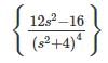
Find the laplace transform of t2sin (2t).
a)
b)
c)
d)
| | Prisha Kulkarni answered |
According to formula, L(tn f(t)) = 
Here, f(t) = sin (2t) ⇒ F(s) =
∴ L(t2sin (2t)) = 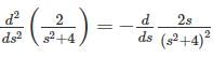 =
= 
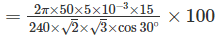
= A three phase half wave controlled rectifier circuit is shown in the figure. It is operated from 3 -Φ star connected, supply transformer with a line to line AC supply voltage of 440 volts rms, at 50 Hz. The thyristors are triggered at a delay angle of ∝ = 30°. Assume continuous ripple free current. What will be the average output current (in ampere)? (Answer up to two decimal places). Also R = 20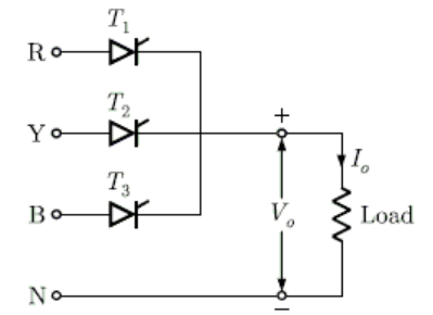 Correct answer is '12.86'. Can you explain this answer?
A three phase half wave controlled rectifier circuit is shown in the figure. It is operated from 3 -Φ star connected, supply transformer with a line to line AC supply voltage of 440 volts rms, at 50 Hz. The thyristors are triggered at a delay angle of ∝ = 30°. Assume continuous ripple free current. What will be the average output current (in ampere)? (Answer up to two decimal places). Also R = 20
| | Pioneer Academy answered |
The average output voltage for continous ripple free output current is,
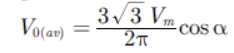
Here Vm is peak value of supply phase voltage . We have

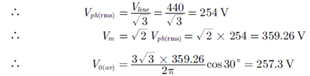
Average output current I0(av)
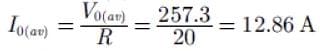
The junction capacitance of thyristor used in the circuit is 15 pF. The limiting value of charging current to turn on thyristor is 5 mA and the critical value dV/dT is 200V/μs . The value of capacitance Cs so that the thyristor will not be turned on due to dV/dT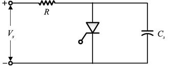
- a)12 pF
- b)7 pF
- c)15 pF
- d)20 pF
Correct answer is option 'B'. Can you explain this answer?
The junction capacitance of thyristor used in the circuit is 15 pF. The limiting value of charging current to turn on thyristor is 5 mA and the critical value dV/dT is 200V/μs . The value of capacitance Cs so that the thyristor will not be turned on due to dV/dT
a)
12 pF
b)
7 pF
c)
15 pF
d)
20 pF
| | Pioneer Academy answered |
Given:
I = 5mA
dV/dt = 200V/μs
I = CdV/dt
Cs= Critical value of Cs to turn on the thyristor due to dV/dT
Actually we don’t want to turn SCR by this method
A 230V, 10 kW dc shunt generator has 1000 turns on each pole. At rated speed, a shunt field current of a 2 A produces no load voltage of 230 V, but at rated load a voltage of 230 V is produced by a field current of 3 A. The number of series field turns per pole required for long shunt connection, if it is made possible to maintain the load voltage constant without changing field current is- a)22
- b)24
- c)18
- d)20
Correct answer is option 'A'. Can you explain this answer?
A 230V, 10 kW dc shunt generator has 1000 turns on each pole. At rated speed, a shunt field current of a 2 A produces no load voltage of 230 V, but at rated load a voltage of 230 V is produced by a field current of 3 A. The number of series field turns per pole required for long shunt connection, if it is made possible to maintain the load voltage constant without changing field current is
a)
22
b)
24
c)
18
d)
20
| | Debanshi Iyer answered |
Total mmf required at rated load
= 3 × 1000 = 3000 AT
Total mmf required at no load
= 2 × 1000 = 2000 AT
The mmf to be supplied by series field winding
= 3000 – 2000 = 1000 AT
The line current at full load,

Armature current = 43.48 + 3 = 46.48 A
Required series filed turns per pole
 turns per pole.
≈ 22 turns per pole.
A fully controlled natural commutated 3-Φ bridge rectifier is operating with a firing angle, α = 300 . The peak to peak ripple voltage,if the maximum phase voltage is 400 V,will be- a)400√3
- b)400
- c)200√3
- d)200
Correct answer is option 'C'. Can you explain this answer?
A fully controlled natural commutated 3-Φ bridge rectifier is operating with a firing angle, α = 300 . The peak to peak ripple voltage,if the maximum phase voltage is 400 V,will be
a)
400√3
b)
400
c)
200√3
d)
200
| | Neha Nambiar answered |
Given:
To find:
Concepts Used:
V0 = √2Vmcosα
Calculation:
V0 = √2Vmcosα
= √2 x 400 x cos300
= √2 x 400 x (0.866)
= 400√3 V
Peak to Peak Ripple Voltage:
Vrpp = V0 / √3
Substituting the value of V0, we get:
Vrpp = 400√3 / √3
= 400 V
Answer:
- Firing angle, α = 300
- Maximum phase voltage, Vm = 400 V
To find:
- Peak to peak ripple voltage
Concepts Used:
- For a fully controlled natural commutated 3-Φ bridge rectifier, the output voltage V0 can be given as:
V0 = √2Vmcosα
Calculation:
- Given firing angle, α = 300
- Maximum phase voltage, Vm = 400 V
- Using the above formula, we can find the output voltage as:
V0 = √2Vmcosα
= √2 x 400 x cos300
= √2 x 400 x (0.866)
= 400√3 V
Peak to Peak Ripple Voltage:
- For a fully controlled natural commutated 3-Φ bridge rectifier, the peak to peak ripple voltage can be given as:
Vrpp = V0 / √3
Vrpp = 400√3 / √3
= 400 V
Answer:
- Peak to peak ripple voltage = 400 V
A 100 MVA synchronous generator operates on full load at a frequency of 50 Hz. Inertia constant is 8 MJ/MVA. The load is suddenly reduced 100 MW. Due to time lag in governor system, the steam valve begins to close after 0.4 seconds. The change in frequency that occurs in this time is_____
Correct answer is between '1.2,1.3'. Can you explain this answer?
A 100 MVA synchronous generator operates on full load at a frequency of 50 Hz. Inertia constant is 8 MJ/MVA. The load is suddenly reduced 100 MW. Due to time lag in governor system, the steam valve begins to close after 0.4 seconds. The change in frequency that occurs in this time is_____
| | Sahil Datta answered |
The rating of the machine (S) = 100 MVA
Inertia constant = H = 8 MJ/MVA
Kinetic energy stored in the rotating parts of the generator = SH = 800 MJ
Energy transferred in 0.4 sec = 100 × 0.4 = 40 MJ
⇒ f2 = 51.23Hz
Change in frequency = 1.23 Hz
A uniform line charge of infinite length with PL = 15 nC/m lies along the z-axis.The electric field at (5, 12, 20) will be – v/m
Correct answer is between '20.5,21'. Can you explain this answer?
A uniform line charge of infinite length with PL = 15 nC/m lies along the z-axis.
The electric field at (5, 12, 20) will be – v/m
| | Mira Mukherjee answered |
Electric field at a point P(x, y, z) is given as
Synchronous reactance is- a)equal to armature leakage reactance
- b)the sum of armature leakage reactance and magnetisation reactance
- c)same as the magnetisation reactance
- d)the difference of armature leakage reactance and magnetisation reactance
Correct answer is option 'B'. Can you explain this answer?
Synchronous reactance is
a)
equal to armature leakage reactance
b)
the sum of armature leakage reactance and magnetisation reactance
c)
same as the magnetisation reactance
d)
the difference of armature leakage reactance and magnetisation reactance
| | Bibek Saha answered |
Synchronous Reactance
The synchronous reactance is an important parameter in the analysis and design of synchronous machines. It represents the opposition offered by the machine to the flow of synchronous current. The synchronous reactance mainly consists of two components - armature leakage reactance and magnetization reactance.
Armature Leakage Reactance
The armature leakage reactance is the reactance due to the leakage flux in the armature winding. When the synchronous machine is in operation, some of the flux produced by the field winding does not link with the armature winding due to leakage. This leakage flux induces an emf in the armature winding, which leads to the flow of armature leakage current. The armature leakage reactance represents the opposition offered by the armature winding to this leakage current.
Magnetization Reactance
The magnetization reactance is the reactance due to the magnetization current required to establish the magnetic field in the machine. When the synchronous machine is excited with a field current, it generates a magnetic field. This magnetic field induces a voltage in the armature winding, which leads to the flow of magnetization current. The magnetization reactance represents the opposition offered by the machine to this magnetization current.
Synchronous Reactance Calculation
The synchronous reactance is the sum of the armature leakage reactance and magnetization reactance. This can be mathematically represented as:
Synchronous Reactance = Armature Leakage Reactance + Magnetization Reactance
This is because both the armature leakage reactance and magnetization reactance contribute to the total opposition offered by the machine to the flow of synchronous current.
Conclusion
In conclusion, the synchronous reactance is equal to the sum of the armature leakage reactance and magnetization reactance. It represents the opposition offered by the synchronous machine to the flow of synchronous current. The armature leakage reactance accounts for the leakage flux in the armature winding, while the magnetization reactance accounts for the magnetization current required to establish the magnetic field. Understanding and accurately calculating the synchronous reactance is essential for the analysis and design of synchronous machines.
Select the most appropriate option to substitute the underlined segment in the given sentence. If there is no need to substitute it, select No improvement.It is not wise relying to anybody too much.- a)to rely in anybody
- b)No improvement.
- c)to rely on anybody
- d)relying at anybody
Correct answer is option 'C'. Can you explain this answer?
Select the most appropriate option to substitute the underlined segment in the given sentence. If there is no need to substitute it, select No improvement.
It is not wise relying to anybody too much.
a)
to rely in anybody
b)
No improvement.
c)
to rely on anybody
d)
relying at anybody
| | Kiran Banerjee answered |
Explanation:
It is not wise relying to anybody too much.
Analysis:
The correct preposition to use after the verb "rely" is "on." Therefore, the correct structure of the sentence should be "It is not wise to rely on anybody too much."
Corrected Sentence:
It is not wise to rely on anybody too much.
Therefore, option (c) - to rely on anybody - is the most appropriate substitution for the underlined segment in the given sentence.
Chapter doubts & questions for Practice and Mock Tests - 6 Months Preparation for GATE Electrical 2026 is part of Electrical Engineering (EE) exam preparation. The chapters have been prepared according to the Electrical Engineering (EE) exam syllabus. The Chapter doubts & questions, notes, tests & MCQs are made for Electrical Engineering (EE) 2026 Exam. Find important definitions, questions, notes, meanings, examples, exercises, MCQs and online tests here.
Chapter doubts & questions of Practice and Mock Tests - 6 Months Preparation for GATE Electrical in English & Hindi are available as part of Electrical Engineering (EE) exam. Download more important topics, notes, lectures and mock test series for Electrical Engineering (EE) Exam by signing up for free.
6 Months Preparation for GATE Electrical675 videos|1390 docs|885 tests |