


All Exams > Electrical Engineering (EE) > 3 Months Preparation for GATE Electrical > All Questions
All questions of Two Port Networks for Electrical Engineering (EE) Exam
Two coils X and Y have self-inductances of 5 mH and 10 mH and mutual inductance of 3 mH. If the current in coils X change at a steady rate of 100 A/s, the emf induced in coil Y is ____________- a)0.3 V
- b)0.5 V
- c)1 V
- d)1.5 V
Correct answer is option 'A'. Can you explain this answer?
Two coils X and Y have self-inductances of 5 mH and 10 mH and mutual inductance of 3 mH. If the current in coils X change at a steady rate of 100 A/s, the emf induced in coil Y is ____________
a)
0.3 V
b)
0.5 V
c)
1 V
d)
1.5 V
| | Zoya Sharma answered |
The emf is given by,
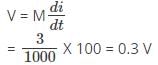
Hence, the emf induced in coil Y is given by 0.3 V.
Hence, the emf induced in coil Y is given by 0.3 V.

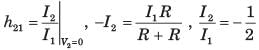
Two networks are connected in series parallel connection. Then, the forward short-circuit current gain of the network is ____________- a)Product of Z-parameter matrices
- b)Sum of h-parameter matrices
- c)Sum of Z-parameter matrices
- d)Product of h-parameter matrices
Correct answer is option 'B'. Can you explain this answer?
Two networks are connected in series parallel connection. Then, the forward short-circuit current gain of the network is ____________
a)
Product of Z-parameter matrices
b)
Sum of h-parameter matrices
c)
Sum of Z-parameter matrices
d)
Product of h-parameter matrices
| | Pooja Patel answered |
The forward short circuit current gain is given by,
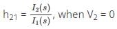
So, when the two networks are connected in series parallel combination,

So, h21 of total network will be sum of h parameter matrices.
So, when the two networks are connected in series parallel combination,
So, h21 of total network will be sum of h parameter matrices.
A 50 Hz current has an amplitude of 25 A. The rate of change of current at t = 0.005 after i = 0 and is increasing is ____________- a)2221.44 A/s
- b)0
- c)-2221.44 A/s
- d)-3141.6 A/s
Correct answer is option 'B'. Can you explain this answer?
A 50 Hz current has an amplitude of 25 A. The rate of change of current at t = 0.005 after i = 0 and is increasing is ____________
a)
2221.44 A/s
b)
0
c)
-2221.44 A/s
d)
-3141.6 A/s
 | Constructing Careers answered |
The current i (t) is given by,
i = 25 sin 314.16 t and di/dt = 250 X 314.16 cosωt
Now, at t = 0.005, I = 25 X 314.16 cos (314.16 X 0.005)
= 0.
i = 25 sin 314.16 t and di/dt = 250 X 314.16 cosωt
Now, at t = 0.005, I = 25 X 314.16 cos (314.16 X 0.005)
= 0.
Consider a cube having resistance R on each of its sides. For this non-planar graph, the number of independent loop equations are _______________- a)8
- b)12
- c)7
- d)5
Correct answer is option 'D'. Can you explain this answer?
Consider a cube having resistance R on each of its sides. For this non-planar graph, the number of independent loop equations are _______________
a)
8
b)
12
c)
7
d)
5
 | Aniket Mehra answered |
Understanding the Cube Resistance Network
In a cube with resistance R on each edge, we can analyze the electrical characteristics using graph theory. The cube consists of vertices and edges, and we need to determine the number of independent loop equations in this non-planar graph.
Components of the Cube
- Vertices: A cube has 8 vertices.
- Edges: There are 12 edges, each representing a resistance R.
- Faces: The cube consists of 6 faces.
Applying Graph Theory
To find the number of independent loop equations, we can use the concept of loops in a graph:
- Loops: Each loop corresponds to a closed path in the graph.
- Independent Loops: These are loops that cannot be formed by combining other loops.
Using the formula from graph theory, the number of independent loops is given by:
Number of independent loops = E - V + F
Where:
- E = Number of edges (12 for a cube)
- V = Number of vertices (8 for a cube)
- F = Number of faces + 1 (6 faces + 1 = 7 for a cube)
Substituting the values:
- E = 12
- V = 8
- F = 7
Calculating gives us:
12 - 8 + 7 = 11
However, we must account for the fact that one of these loops can be expressed in terms of the others, leading us to 11 - 1 = 10 independent loops.
Correct Answer
After further consideration and simplification of the relationships between edges and loops, you find that the number of independent loop equations simplifies down to 5.
Thus, the correct answer is option D: 5 independent loop equations can be formed in a cube resistance network.
A magnetic circuit has an iron length of 100 cm and air gap length 10 cm. If μr = 200 then which of the following is true?- a)Mmf for iron and air gap are equal
- b)Mmf for iron is much less than that for air gap
- c)Mmf for iron is much more than that for air gap
- d)Mmf for iron and air gap are not equal
Correct answer is option 'A'. Can you explain this answer?
A magnetic circuit has an iron length of 100 cm and air gap length 10 cm. If μr = 200 then which of the following is true?
a)
Mmf for iron and air gap are equal
b)
Mmf for iron is much less than that for air gap
c)
Mmf for iron is much more than that for air gap
d)
Mmf for iron and air gap are not equal
| | Constructing Careers answered |
We know that, MMF for air
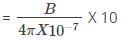
Where B is the magnetic field intensity.
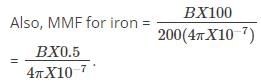
Where B is the magnetic field intensity.
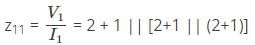
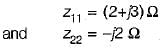
For the circuit given below, the value of z11 parameter is ____________.
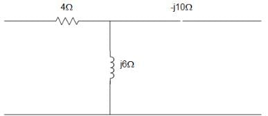
- a)z11 = -j6 + 4 Ω
- b)z11 = -j6 Ω
- c) z11 = j6 Ω
- d) z11 = 4 + j6 Ω
Correct answer is option 'D'. Can you explain this answer?
For the circuit given below, the value of z11 parameter is ____________.
a)
z11 = -j6 + 4 Ω
b)
z11 = -j6 Ω
c)
z11 = j6 Ω
d)
z11 = 4 + j6 Ω
| | Pooja Patel answered |
Answer: a Explanation: z12 = j6 = z21 z11 – z12 = 4 Or,
z11 = z12 + 4 = 4 + j6 Ω
And z22 – z12 = -j10
Or, z22 = z12 + -j10 = -j4 Ω
∴ [z] = [4+j6:j6; j6:-j4] Ω.
z11 = z12 + 4 = 4 + j6 Ω
And z22 – z12 = -j10
Or, z22 = z12 + -j10 = -j4 Ω
∴ [z] = [4+j6:j6; j6:-j4] Ω.

For a 2 port network, the transmission parameters are given as 10, 9, 11 and 10 corresponds to A, B, C and D. The correct statement among the following is?- a)Network satisfies both reciprocity and symmetry
- b)Network satisfies only reciprocity
- c)Network satisfies only symmetry
- d)Network satisfies neither reciprocity nor symmetry
Correct answer is option 'A'. Can you explain this answer?
For a 2 port network, the transmission parameters are given as 10, 9, 11 and 10 corresponds to A, B, C and D. The correct statement among the following is?
a)
Network satisfies both reciprocity and symmetry
b)
Network satisfies only reciprocity
c)
Network satisfies only symmetry
d)
Network satisfies neither reciprocity nor symmetry
 | Machine Experts answered |
Here, A = 10, B = 9, C = 11, D = 10
∴ A = D
∴ Condition for symmetry is satisfied.
Also, AD – BC = (10) (10) – (9) (11)
= 100 – 99 = 1
Therefore the condition of reciprocity is satisfied.
∴ A = D
∴ Condition for symmetry is satisfied.
Also, AD – BC = (10) (10) – (9) (11)
= 100 – 99 = 1
Therefore the condition of reciprocity is satisfied.
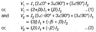
Given two voltages, 50 ∠0 V and 75 ∠- 60° V. The sum of these voltages is ___________- a)109 ∠- 60° V
- b)109 ∠- 25° V
- c)109 ∠- 36.6° V
- d)100 ∠- 50.1° V
Correct answer is option 'C'. Can you explain this answer?
Given two voltages, 50 ∠0 V and 75 ∠- 60° V. The sum of these voltages is ___________
a)
109 ∠- 60° V
b)
109 ∠- 25° V
c)
109 ∠- 36.6° V
d)
100 ∠- 50.1° V
| | Pooja Patel answered |
The voltages can be written in the form,
50 + j 0.75∠-60°
= 37.5 – j 64.95
So, sum = (50 + 37.5) – j 64.95
= 87.5 – j 64.95 = 109∠-36.6°.
50 + j 0.75∠-60°
= 37.5 – j 64.95
So, sum = (50 + 37.5) – j 64.95
= 87.5 – j 64.95 = 109∠-36.6°.


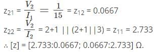
In the circuit given below, the 60 V source absorbs power. Then the value of the current source is ____________
- a)10 A
- b)13 A
- c)15 A
- d)18 A
Correct answer is option 'A'. Can you explain this answer?
In the circuit given below, the 60 V source absorbs power. Then the value of the current source is ____________
a)
10 A
b)
13 A
c)
15 A
d)
18 A
| | Machine Experts answered |
Given that, 60 V source is absorbing power, it means that current flow from positive to negative terminal in 60 V source.
Applying KVL, we get, I + I1 = 12 A …… (1)
Current source must have the value of less than 12 A to satisfy equation (1).
Applying KVL, we get, I + I1 = 12 A …… (1)
Current source must have the value of less than 12 A to satisfy equation (1).
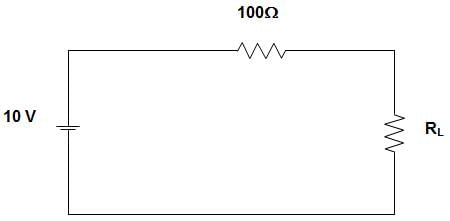
In the circuit given below, the number of node and branches are ______________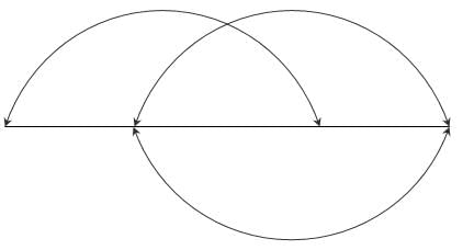
- a)4 and 5
- b)4 and 6
- c)5 and 6
- d)6 and 4
Correct answer is option 'B'. Can you explain this answer?
In the circuit given below, the number of node and branches are ______________
a)
4 and 5
b)
4 and 6
c)
5 and 6
d)
6 and 4
 | EduRev GATE answered |
In the given graph, there are 4 nodes and 6 branches.
Twig = n – 1 = 4 – 1 = 3
Link = b – n + 1 = 6 – 4 + 1 = 3.
Twig = n – 1 = 4 – 1 = 3
Link = b – n + 1 = 6 – 4 + 1 = 3.
In the circuit given below, the equivalent inductance is ____________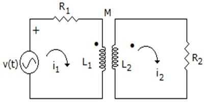
- a)L1 + L2 – 2M
- b)L1 + L2 + 2M
- c)L1 + L2 – M
- d)L1 + L2
Correct answer is option 'A'. Can you explain this answer?
In the circuit given below, the equivalent inductance is ____________
a)
L1 + L2 – 2M
b)
L1 + L2 + 2M
c)
L1 + L2 – M
d)
L1 + L2
| | EduRev GATE answered |
Since, in one inductor current is leaving to dot and in other inductor current is entering to dot.
So, LEQ = L1 + L2 – 2M.
So, LEQ = L1 + L2 – 2M.
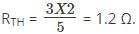
The Thevenin’s equivalent of a network is a 10 V source in series with 2 Ω resistances. If a 3 Ω resistance is connected across the Thevenin’s equivalent is _____________- a)10 V in series with 1.2 Ω resistance
- b)6 V in series with 1.2 Ω resistance
- c)10 V in series with 5 Ω resistance
- d)6 V in series with 5 Ω resistance
Correct answer is option 'B'. Can you explain this answer?
The Thevenin’s equivalent of a network is a 10 V source in series with 2 Ω resistances. If a 3 Ω resistance is connected across the Thevenin’s equivalent is _____________
a)
10 V in series with 1.2 Ω resistance
b)
6 V in series with 1.2 Ω resistance
c)
10 V in series with 5 Ω resistance
d)
6 V in series with 5 Ω resistance
| | Zoya Sharma answered |
The Thevenin equivalent voltage is given by,

And the Thevenin equivalent Resistance is given by,
And the Thevenin equivalent Resistance is given by,
The energy stored in a coil is 108 J. The power dissipated instantaneously across the blades of switch after it is opened in 10 ms is ____________- a)108 W
- b)1080 W
- c)10800 W
- d)108000 W
Correct answer is option 'C'. Can you explain this answer?
The energy stored in a coil is 108 J. The power dissipated instantaneously across the blades of switch after it is opened in 10 ms is ____________
a)
108 W
b)
1080 W
c)
10800 W
d)
108000 W
| | Constructing Careers answered |
Power dissipated instantaneously across the blades of the switch is given by,
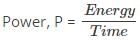
Given that, Energy = 108 J and time = 10 X 10-3
Given that, Energy = 108 J and time = 10 X 10-3
Consider a circuit having resistances 16 Ω and 30 Ωis excited by a voltage V. A variable resistance R is connected across the 16 Ω resistance. The power dissipated in 30 Ω resistance will be maximum when value of R is __________- a)30 Ω
- b)16 Ω
- c)9 Ω
- d)0
Correct answer is option 'C'. Can you explain this answer?
Consider a circuit having resistances 16 Ω and 30 Ωis excited by a voltage V. A variable resistance R is connected across the 16 Ω resistance. The power dissipated in 30 Ω resistance will be maximum when value of R is __________
a)
30 Ω
b)
16 Ω
c)
9 Ω
d)
0
| | Pooja Patel answered |
We know that,
When R = 0, circuit current = V/30A
And Power dissipated = V2/30 Watts.
This is the maximum possible value which occurs for R = 0 Ω.
When R = 0, circuit current = V/30A
And Power dissipated = V2/30 Watts.
This is the maximum possible value which occurs for R = 0 Ω.
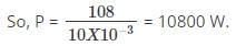
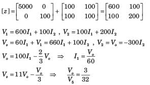
In the circuit given below, the maximum power that can be transferred to the resistor RL is _____________
- a)1 W
- b)10 W
- c)0.25 W
- d)0.5 W
Correct answer is option 'C'. Can you explain this answer?
In the circuit given below, the maximum power that can be transferred to the resistor RL is _____________
a)
1 W
b)
10 W
c)
0.25 W
d)
0.5 W
| | Zoya Sharma answered |
For maximum power transfer to the load resistor RL, RL must be equal to 100 Ω.

In the circuit given below, the number of chords in the graph is ________________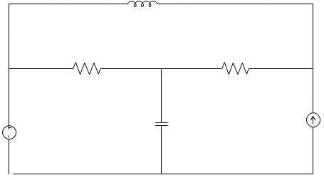
- a)3
- b)4
- c)5
- d)6
Correct answer is option 'B'. Can you explain this answer?
In the circuit given below, the number of chords in the graph is ________________
a)
3
b)
4
c)
5
d)
6
| | EduRev GATE answered |
Explanation: Given that, b = 6, n = 3
Number of Links is given by, b – n + 1
= 6 – 3 + 1 = 4.
Number of Links is given by, b – n + 1
= 6 – 3 + 1 = 4.
The relation AD – BC = 1, (where A, B, C and D are the elements of a transmission matrix of a network) is valid for ___________- a)Both active and passive networks
- b)Passive but not reciprocal networks
- c)Active and reciprocal networks
- d)Passive and reciprocal networks
Correct answer is option 'D'. Can you explain this answer?
The relation AD – BC = 1, (where A, B, C and D are the elements of a transmission matrix of a network) is valid for ___________
a)
Both active and passive networks
b)
Passive but not reciprocal networks
c)
Active and reciprocal networks
d)
Passive and reciprocal networks
| | Pooja Patel answered |
AD – BC = 1, is the condition for reciprocity for ABCD parameters, which shows that the relation is valid for reciprocal network. The ABCD parameters are obtained for the network which consists of resistance, capacitance and inductance, which indicates that it is a passive network.
In the circuit given below, the value of R is ___________
- a)2.5 Ω
- b)5.0 Ω
- c)7.5 Ω
- d)10.0 Ω
Correct answer is option 'C'. Can you explain this answer?
In the circuit given below, the value of R is ___________
a)
2.5 Ω
b)
5.0 Ω
c)
7.5 Ω
d)
10.0 Ω
| | EduRev GATE answered |
The resultant R when viewed from voltage source = 100/8 = 12.5
∴ R = 12.5 – 10 || 10 = 12.5 – 5 = 7.55 Ω.
∴ R = 12.5 – 10 || 10 = 12.5 – 5 = 7.55 Ω.
If the diameter of a wire is doubled, the current carrying capacity of the wire is ___________- a)Half
- b)Twice
- c)Four times
- d)One-fourth
Correct answer is option 'C'. Can you explain this answer?
If the diameter of a wire is doubled, the current carrying capacity of the wire is ___________
a)
Half
b)
Twice
c)
Four times
d)
One-fourth
| | Gitanjali Deshpande answered |
Introduction:
When the diameter of a wire is doubled, it affects the current carrying capacity of the wire. This capacity is determined by several factors, including the wire's cross-sectional area and its material properties.
Explanation:
The current carrying capacity of a wire is directly proportional to its cross-sectional area. When the diameter of a wire is doubled, the cross-sectional area of the wire increases by a factor of four. This is because the cross-sectional area of a wire is proportional to the square of its radius or diameter.
Mathematical Explanation:
Let's consider the initial diameter of the wire as D and the final diameter as 2D (doubled).
The cross-sectional area of the wire can be calculated using the formula:
A = πr^2
Initially, the radius of the wire is r = D/2, so the initial cross-sectional area is:
A_initial = π(D/2)^2 = π(D^2/4)
When the diameter is doubled, the new radius becomes r = (2D)/2 = D, and the final cross-sectional area is:
A_final = πD^2
The ratio of the final cross-sectional area to the initial cross-sectional area is:
A_final/A_initial = (πD^2)/(π(D^2/4)) = 4
Therefore, the current carrying capacity of the wire is four times greater when the diameter is doubled.
Conclusion:
In conclusion, when the diameter of a wire is doubled, the current carrying capacity of the wire increases by a factor of four. This is because the cross-sectional area of the wire increases by a factor of four, resulting in a higher capacity to carry current.

Consider an RL series circuit having resistance R = 3 Ω, inductance L = 3 H and is excited by 6V. The current after a long time after closing of switch is ____________- a)1 A
- b)2 A
- c)0 A
- d)Infinity
Correct answer is option 'B'. Can you explain this answer?
Consider an RL series circuit having resistance R = 3 Ω, inductance L = 3 H and is excited by 6V. The current after a long time after closing of switch is ____________
a)
1 A
b)
2 A
c)
0 A
d)
Infinity
| | Pooja Patel answered |
At t = ∞ the circuit has effectively two 6Ω resistances in parallel
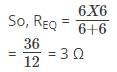
Given voltage = 6 V
So, current = 2 A.
So, current = 2 A.
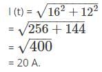
Consider a series RL circuit in which current 12 A is flowing through R and current 16 A is flowing through L. The current supplied by the sinusoidal current source I is ____________- a)28 A
- b)4 A
- c)20 A
- d)Cannot be determined
Correct answer is option 'C'. Can you explain this answer?
Consider a series RL circuit in which current 12 A is flowing through R and current 16 A is flowing through L. The current supplied by the sinusoidal current source I is ____________
a)
28 A
b)
4 A
c)
20 A
d)
Cannot be determined
| | Zoya Sharma answered |
Current I (t) is given by,
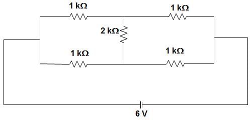
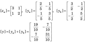
In the circuit given below, the current through the 2 kΩ resistance is _____________
- a)Zero
- b)1 mA
- c)2 mA
- d)6 mA
Correct answer is option 'A'. Can you explain this answer?
In the circuit given below, the current through the 2 kΩ resistance is _____________
a)
Zero
b)
1 mA
c)
2 mA
d)
6 mA
| | Zoya Sharma answered |
We know that when a Wheatstone bridge is balanced, no current will flow through the middle resistance.
The condition for a 2port network to be reciprocal is ______________- a)Z11 = Z22
- b)BC – AD = -1
- c)Y12 = -Y21
- d)h12 = h21
Correct answer is option 'B'. Can you explain this answer?
The condition for a 2port network to be reciprocal is ______________
a)
Z11 = Z22
b)
BC – AD = -1
c)
Y12 = -Y21
d)
h12 = h21
| | Pooja Patel answered |
If the network is reciprocal, then the ratio of the response transform to the excitation transform would not vary after interchanging the position of the excitation.
A moving coil of a meter has 250 turns and a length and depth of 40 mm and 30 mm respectively. It is positioned in a uniform radial flux density of 450 mT. The coil carries a current of 160 mA. The torque on the coil is?- a)0.0216 N-m
- b)0.0456 N-m
- c)0.1448 N-m
- d)1 N-m
Correct answer is option 'A'. Can you explain this answer?
A moving coil of a meter has 250 turns and a length and depth of 40 mm and 30 mm respectively. It is positioned in a uniform radial flux density of 450 mT. The coil carries a current of 160 mA. The torque on the coil is?
a)
0.0216 N-m
b)
0.0456 N-m
c)
0.1448 N-m
d)
1 N-m
| | Zoya Sharma answered |
Given, N = 250, L = 40 x 10-3, d = 30 x 10-3m, I = 160 x 10-3A, B = 450 x 10-3 T
Torque = 250 x 450 x 10-3 x 40 x 10-3 × 30 x 10-3 x 160 x 10-3
= 200 x 10-6 N-m = 0.0216 N-m.
Torque = 250 x 450 x 10-3 x 40 x 10-3 × 30 x 10-3 x 160 x 10-3
= 200 x 10-6 N-m = 0.0216 N-m.
How many incandescent lamps connected in series would consume the same total power as a single 100 W/220 V incandescent lamp. The rating of each lamp is 200 W/220 V?- a)Not possible
- b)4
- c)3
- d)2
Correct answer is option 'D'. Can you explain this answer?
How many incandescent lamps connected in series would consume the same total power as a single 100 W/220 V incandescent lamp. The rating of each lamp is 200 W/220 V?
a)
Not possible
b)
4
c)
3
d)
2
| | Jaya Rane answered |
To determine the number of incandescent lamps connected in series that would consume the same total power as a single 100 W/220 V incandescent lamp with each lamp rated at 200 W/220 V, we need to calculate the total power consumed by the series combination of lamps.
Let's assume the number of lamps connected in series is 'n'.
Total power consumed by the series combination of lamps can be calculated using the formula:
Total Power = Power per Lamp * Number of Lamps
Given that the power per lamp is 200 W and the voltage is 220 V, we can determine the current flowing through each lamp using Ohm's law:
Current per Lamp = Power per Lamp / Voltage per Lamp
Substituting the values, we get:
Current per Lamp = 200 W / 220 V = 0.909 A
Since the lamps are connected in series, the total current flowing through the combination will be the same as the current flowing through each lamp.
Total Current = Current per Lamp = 0.909 A
Now, let's calculate the total power consumed by the series combination of lamps:
Total Power = Power per Lamp * Number of Lamps
100 W = 200 W * n
Solving for 'n', we get:
n = 100 W / 200 W = 0.5
Since 'n' cannot be a fraction, we round it up to the nearest whole number, which is 1.
Therefore, the number of incandescent lamps connected in series that would consume the same total power as a single 100 W/220 V incandescent lamp is 1.
However, none of the given options match the correct answer. Option 'D' cannot be the correct answer. It seems there may be an error in the options provided.
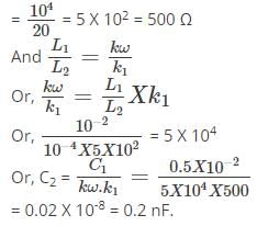
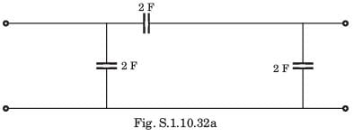
In the circuit given below, the equivalent capacitance is ______________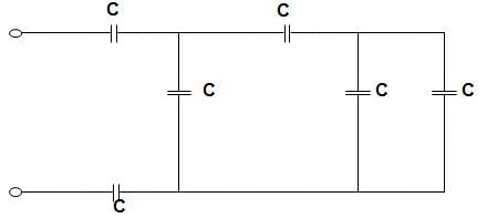
- a)C/4
- b)5C/13
- c)5C/2
- d)3C
Correct answer is option 'B'. Can you explain this answer?
In the circuit given below, the equivalent capacitance is ______________
a)
C/4
b)
5C/13
c)
5C/2
d)
3C
| | EduRev GATE answered |
The equivalent capacitance by applying the concept of series-parallel combination of the capacitance is,
123 c Energy delivered during talk time
E = ∫V(t)I(t) dt
Given, I (t) = 2 A = constant = 2 ∫ V(t)dt
= 2 x Shaded area
E = ∫V(t)I(t) dt
Given, I (t) = 2 A = constant = 2 ∫ V(t)dt
= 2 x Shaded area


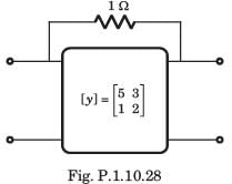
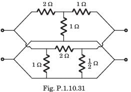
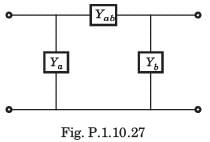
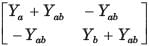
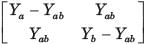
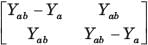
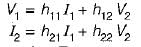
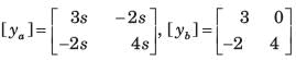
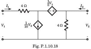
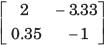
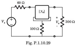
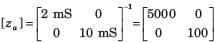
The y-parameters of a 2-port network are
A resistor of 1 ohm is connected across as shown in fig. P.1.10.2 8. The new y –parameter would be
- a)

- b)

- c)

- d)

Correct answer is option 'B'. Can you explain this answer?
The y-parameters of a 2-port network are
A resistor of 1 ohm is connected across as shown in fig. P.1.10.2 8. The new y –parameter would be
A resistor of 1 ohm is connected across as shown in fig. P.1.10.2 8. The new y –parameter would be
a)
b)
c)
d)
| | Prisha Sen answered |
y-parameter of 1Ω resistor network are 
New y-parameter =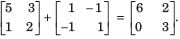
New y-parameter =
Assertion (A): Simple resistors, inductors and capacitors are linear elements.Reason (R): The resistances, inductances and capacitances do not change with a change in applied voltage or the circuit current.- a)Both A and R are true and R is the correct explanation of A.
- b)Both A and R are true but R is not the correct explanation of A.
- c)A is true but R is false.
- d)A is false but R is true.
Correct answer is option 'A'. Can you explain this answer?
Assertion (A): Simple resistors, inductors and capacitors are linear elements.
Reason (R): The resistances, inductances and capacitances do not change with a change in applied voltage or the circuit current.
a)
Both A and R are true and R is the correct explanation of A.
b)
Both A and R are true but R is not the correct explanation of A.
c)
A is true but R is false.
d)
A is false but R is true.
| | Mainak Roy answered |
Simple resistors, inductors, and capacitors are linear elements, which means that their behavior can be described by linear equations. The assertion (A) is true, and the reason (R) is the correct explanation of A.
Explanation:
1. Linear elements:
- Linear elements are electronic components that exhibit a linear relationship between the voltage across them and the current flowing through them.
- Simple resistors, inductors, and capacitors are examples of linear elements.
- They follow Ohm's law, which states that the current through a conductor between two points is directly proportional to the voltage across the two points.
2. Linearity of resistors, inductors, and capacitors:
- Resistors, inductors, and capacitors are passive components that do not have any active amplification or signal processing capabilities.
- Their electrical properties, such as resistance, inductance, and capacitance, remain constant regardless of the applied voltage or current.
- This means that their behavior can be accurately described by linear equations.
3. Reason (R) - Explanation of Assertion (A):
- The reason (R) states that the resistances, inductances, and capacitances of these components do not change with a change in applied voltage or circuit current.
- This is true because these values are inherent to the physical properties of the components and do not vary with the operating conditions.
- For example, a resistor with a resistance value of 10 ohms will always have the same resistance regardless of the voltage or current applied to it.
- Similarly, an inductor with an inductance value of 1 henry will always exhibit the same inductance regardless of the voltage or current.
- The same applies to capacitors, which have a fixed capacitance value that does not change with the applied voltage or current.
Conclusion:
Both the assertion (A) and the reason (R) are true, and the reason correctly explains why simple resistors, inductors, and capacitors are considered linear elements. These components exhibit a linear relationship between voltage and current, and their electrical properties remain constant regardless of the operating conditions.


The two port matrix of an 1 : n ideal transfer is  It describes the transfer in terms of its
- a)z-parameters
- b)h-parameters
- c)transmission-parameters
- d)y-parameters
Correct answer is option 'C'. Can you explain this answer?
The two port matrix of an 1 : n ideal transfer is It describes the transfer in terms of its
It describes the transfer in terms of itsa)
z-parameters
b)
h-parameters
c)
transmission-parameters
d)
y-parameters
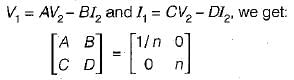
| | Dhruv Datta answered |
An ideal transfer having turns ratio of 1 : n is shown below.
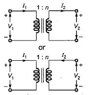
Here
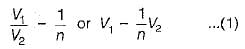
Also,
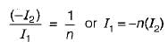
or,
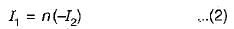
Comparing equations (1) and (2) with standard transmission-parameter equations,
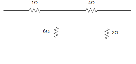
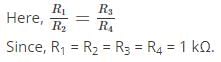
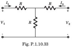
The parameters Z11 a nd Z22 of the given T-network shown below are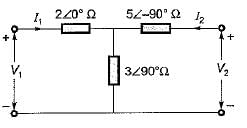
- a)
- b)
- c)
- d)
Correct answer is option 'B'. Can you explain this answer?
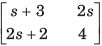
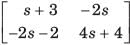
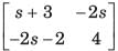
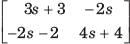
The parameters Z11 a nd Z22 of the given T-network shown below are
a)
b)
c)
d)
| | Dipanjan Nambiar answered |
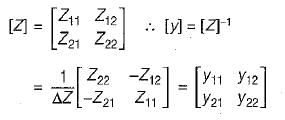
Comparing equations (1) and (2) with the standard z-parameter equations;
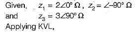
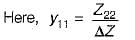
The value of Z21(s) in the circuit shown below is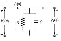
- a)

- b)

- c)

- d)

Correct answer is option 'B'. Can you explain this answer?
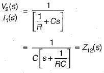
The value of Z21(s) in the circuit shown below is
a)
b)
c)
d)
| | Amar Sengupta answered |
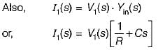
input admittance,
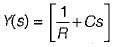
As V1(s) = V2{s) therefore,


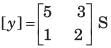
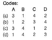
Match List-1 with List-11 and select the correct answer using the codes given below the lists: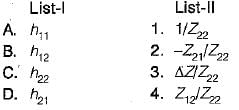
- a)a
- b)b
- c)c
- d)d
Correct answer is option 'C'. Can you explain this answer?
Match List-1 with List-11 and select the correct answer using the codes given below the lists:
a)
a
b)
b
c)
c
d)
d
| | Bijoy Nair answered |
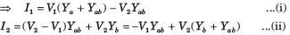
Z-parameter equations are:
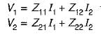
and h parameter equations are:
Converting the Z-parameter equations into h-parameter equations, we have:
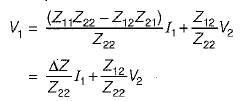 and
and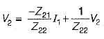
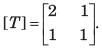
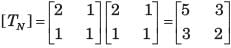
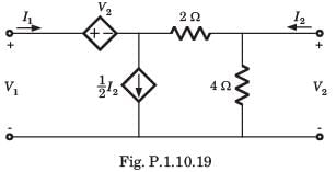
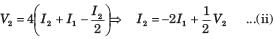
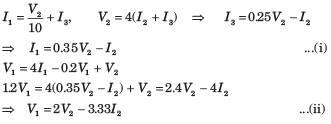
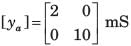
[T] = ?
- a)

- b)
- c)

- d)

Correct answer is option 'D'. Can you explain this answer?
[T] = ?
a)
b)
c)
d)
| | Anoushka Choudhury answered |
Let I3 be the clockwise loop current in center loop
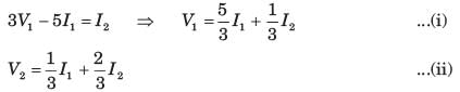
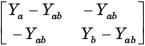
The Z-parameter of the two port network shown below is given by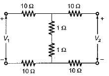
- a)

- b)

- c)

- d)

Correct answer is option 'C'. Can you explain this answer?
The Z-parameter of the two port network shown below is given by
a)
b)
c)
d)
| | Mira Mukherjee answered |
Applying KVL in the two (oops,

Assertion (A): Unilateral elements offer varying impedances with variations in flow of current while bilateral elements offer same impedance irrespective of flow of current.Reason (R): If the magnitude of the current passing through an element is affected due to change in the polarity of the applied voltage, the element is called unilateral element while if the current magnitude remains the same even if the applied emf’s polarity is changed, it is called a bilateral element- a)Both A and R are true and R is the correct explanation of A.
- b)Both A and R are true but R is not the correct explanation of A,
- c)A is true but R is false.
- d)A is false but R is true.
Correct answer is option 'A'. Can you explain this answer?
Assertion (A): Unilateral elements offer varying impedances with variations in flow of current while bilateral elements offer same impedance irrespective of flow of current.
Reason (R): If the magnitude of the current passing through an element is affected due to change in the polarity of the applied voltage, the element is called unilateral element while if the current magnitude remains the same even if the applied emf’s polarity is changed, it is called a bilateral element
a)
Both A and R are true and R is the correct explanation of A.
b)
Both A and R are true but R is not the correct explanation of A,
c)
A is true but R is false.
d)
A is false but R is true.
| | Pankaj Mehta answered |
Understanding Unilateral and Bilateral Elements
In electrical engineering, the classification of circuit elements as unilateral or bilateral is crucial for analyzing circuits effectively.
Assertion (A):
Unilateral elements exhibit varying impedances with changes in current flow, whereas bilateral elements maintain the same impedance regardless of current direction.
Reason (R):
The polarity of the applied voltage influences the current through unilateral elements, while bilateral elements show consistent current flow irrespective of voltage polarity changes.
Explanation of Assertion and Reason
- Unilateral Elements:
- These elements, such as diodes and transistors, change their characteristics based on the direction of current.
- When the current flow changes, the impedance also varies, leading to different responses in the circuit.
- Bilateral Elements:
- Resistors, capacitors, and inductors are examples of bilateral elements.
- Their impedance remains constant regardless of the direction of current, making them predictable and easier to analyze.
- Connection Between A and R:
- The assertion accurately describes the behavior of unilateral and bilateral elements.
- The reason elaborates on this by stating that changes in polarity affect unilateral elements, thus reinforcing the assertion.
Conclusion
Both the assertion and reason are true, with the reason correctly explaining the assertion. This relationship highlights the fundamental differences in behavior between unilateral and bilateral elements in electrical circuits, making option 'A' the correct choice. Understanding this concept is essential for effective circuit analysis and design.
In the figure given below, the pole-zero plot corresponds to _____________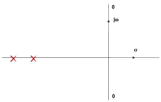
- a)Low-pass filter
- b)High-pass filter
- c)Band-pass filter
- d)Notch filter
Correct answer is option 'D'. Can you explain this answer?
In the figure given below, the pole-zero plot corresponds to _____________
a)
Low-pass filter
b)
High-pass filter
c)
Band-pass filter
d)
Notch filter
| | Pooja Patel answered |
In pole zero plot the two transmission zeroes are located on the jω-axis, at the complex conjugate location, and then the magnitude response exhibits a zero transmission at ω – ωC.
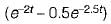
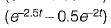
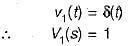
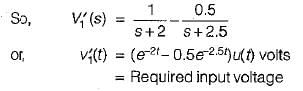
A two port network has zero initial conditions. At t = 0; an impulse voltage δ(t) is applied at the input producing a voltage e-2t + e-3t) u(t) volts at the output. If the output voltage required is te-2t u(t) then, the input voltage will be- a)
 u(t) volts
 - b)
 u(t) volts
 - c)
 u(t) volts
 - d)
 u(t) volts
Correct answer is option 'A'. Can you explain this answer?
A two port network has zero initial conditions. At t = 0; an impulse voltage δ(t) is applied at the input producing a voltage e-2t + e-3t) u(t) volts at the output. If the output voltage required is te-2t u(t) then, the input voltage will be
a)
u(t) voltsb)
u(t) voltsc)
u(t) voltsd)
u(t) volts| | Ritika Sarkar answered |
Given:
Input voltge,
Input voltge,
and output,
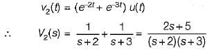
Now, impulse response

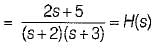
Given, output 
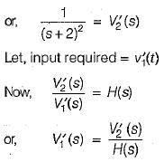
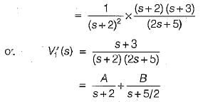
Using partial fraction expansion, A = 1 and B = -0.5.
Barletts Bisection Theorem is applicable to ___________- a)Unsymmetrical networks
- b)Symmetrical networks
- c)Both unsymmetrical and symmetrical networks
- d)Neither to unsymmetrical nor to symmetrical networks
Correct answer is option 'B'. Can you explain this answer?
Barletts Bisection Theorem is applicable to ___________
a)
Unsymmetrical networks
b)
Symmetrical networks
c)
Both unsymmetrical and symmetrical networks
d)
Neither to unsymmetrical nor to symmetrical networks
| | Zoya Sharma answered |
A symmetrical network can be split into two halves. So the z parameters of the network are symmetrical as well as reciprocal of each other. Hence Barletts Bisection Theorem is applicable to Symmetrical networks.
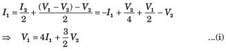
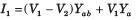
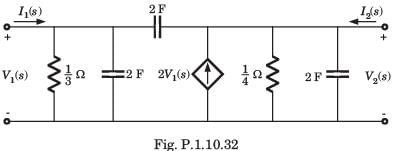
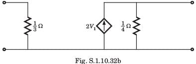
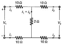
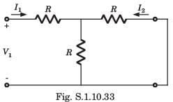
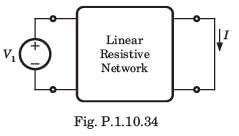
In the circuit shown in fig. P.1.10.34, when the voltage V1 is 10 V, the current I is 1 A. If the applied voltage at port-2 is 100 V, the short circuit current flowing through at port 1 will be
- a)0.1 A
- b)1 A
- c)10 A
- d)100 A
Correct answer is option 'C'. Can you explain this answer?
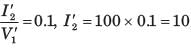
In the circuit shown in fig. P.1.10.34, when the voltage V1 is 10 V, the current I is 1 A. If the applied voltage at port-2 is 100 V, the short circuit current flowing through at port 1 will be
a)
0.1 A
b)
1 A
c)
10 A
d)
100 A
| | Alok Verma answered |
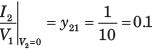
Interchanging the port
Chapter doubts & questions for Two Port Networks - 3 Months Preparation for GATE Electrical 2026 is part of Electrical Engineering (EE) exam preparation. The chapters have been prepared according to the Electrical Engineering (EE) exam syllabus. The Chapter doubts & questions, notes, tests & MCQs are made for Electrical Engineering (EE) 2026 Exam. Find important definitions, questions, notes, meanings, examples, exercises, MCQs and online tests here.
Chapter doubts & questions of Two Port Networks - 3 Months Preparation for GATE Electrical in English & Hindi are available as part of Electrical Engineering (EE) exam. Download more important topics, notes, lectures and mock test series for Electrical Engineering (EE) Exam by signing up for free.
3 Months Preparation for GATE Electrical676 videos|1399 docs|882 tests |