


All Exams > Electrical Engineering (EE) > 3 Months Preparation for GATE Electrical > All Questions
All questions of Transient Analysis in AC & DC Circuits for Electrical Engineering (EE) Exam
In an R-L circuit connected to an alternating sinusoidal voltage, size of transient current primarily depends on:- a)the voltage frequency
- b)the circuit impedance
- c)the instant in the voltage cycle at which circuit is closed
- d)the peak value of steady-state current
Correct answer is option 'C'. Can you explain this answer?
In an R-L circuit connected to an alternating sinusoidal voltage, size of transient current primarily depends on:
a)
the voltage frequency
b)
the circuit impedance
c)
the instant in the voltage cycle at which circuit is closed
d)
the peak value of steady-state current
 | Cstoppers Instructors answered |
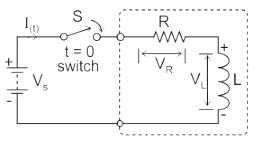
Series RL circuit:
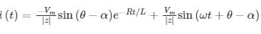
Let the voltage be Vs(t) = Vm sin ωt

The transient current equation is
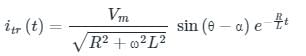
where
Vm = Peak value of voltage
θ = Peak value of impedance angle
ω = angular frequency
R = Resistance
L = Inductance
α = instant at which the circuit is closed
θ = Impedance angle
The exponential decay term represents the transient term and the remaining is the steady-state term.
The response is shown below;
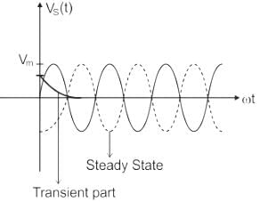
In the steady-state, the RLC circuit elements give a response that is in synchronization to the input frequency.
Because transient analysis expressions consist of exponential decay terms.
Size of transient current primarily depends on the instant in the voltage cycle at which circuit is closed i.e. it depends on α value.

For a critically damped second-order system, what is the time constant τ?- a)1/ωn
- b)2/ωn
- c)1/(2ωn)
- d)ωn
Correct answer is option 'A'. Can you explain this answer?
For a critically damped second-order system, what is the time constant τ?
a)
1/ωn
b)
2/ωn
c)
1/(2ωn)
d)
ωn
| | Akanksha Chopra answered |
Understanding Critically Damped Second-Order Systems
In control systems, a critically damped second-order system achieves the fastest response without oscillation. The time constant, denoted as τ, is crucial for determining the system's response dynamics.
Key Concepts of Critically Damped Systems
- Natural Frequency (ωn): This represents the frequency at which the system would oscillate if there were no damping.
- Damping Ratio: For critically damped systems, the damping ratio equals 1, leading to a specific response characteristic.
Time Constant τ
In critically damped systems, the time constant τ is defined as the time it takes for the system to respond to a step input. The relationship between the time constant and the natural frequency is given by:
- Formula for Time Constant: τ = 1 / ωn
This indicates that as the natural frequency increases, the time constant decreases, leading to a faster system response.
Why Option A is Correct
- The correct answer is 1 / ωn.
- This choice reflects the relationship between the time constant and the natural frequency of the critically damped system.
Comparison with Other Options
- Option B (2 / ωn): This would imply a slower response, not characteristic of critical damping.
- Option C (1 / (2ωn)): This suggests an alternative damping context, not applicable here.
- Option D (ωn): Represents the natural frequency itself, not a time constant.
In summary, for a critically damped second-order system, the time constant τ is indeed 1 / ωn, making option A the correct choice. Understanding this relationship is essential for analyzing system behavior in control engineering.
What is the phase angle between the capacitor current and the applied voltage in a parallel RC circuit?- a)90°
- b)0°
- c)45°
- d)180°
Correct answer is option 'A'. Can you explain this answer?
What is the phase angle between the capacitor current and the applied voltage in a parallel RC circuit?
a)
90°
b)
0°
c)
45°
d)
180°
 | Naroj Boda answered |
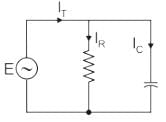
The phasor diagram is drawn as:
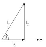
1) There is no phase difference between the applied voltage and the voltage across R and C in parallel.
2) The current through the resistive branch is in phase with the applied signal.
3) But the current through the capacitive branch leads its voltage Vc by 90 degrees.
.
The output in response to a unit step input for a particular continuous control system is c(t)= 1-e-t. What is the delay time Td?- a)0.36
- b)0.18
- c)0.693
- d)0.289
Correct answer is option 'C'. Can you explain this answer?
The output in response to a unit step input for a particular continuous control system is c(t)= 1-e-t. What is the delay time Td?
a)
0.36
b)
0.18
c)
0.693
d)
0.289
| | Cstoppers Instructors answered |
The output is given as a function of time. The final value of the output is limn->∞c(t) = 1; .
Hence Td (at 50% of the final value) is the solution of 0.5 = 1-e-Td, and is equal to ln 2 or 0.693 sec.
The transfer function of the system is G(s) = 100/(s + 1) (s + 100). For a unit step input to the system the approximate settling time for 2% criterion is:- a)100 sec
- b)4 sec
- c)1 sec
- d)0.01 sec
Correct answer is option 'B'. Can you explain this answer?
The transfer function of the system is G(s) = 100/(s + 1) (s + 100). For a unit step input to the system the approximate settling time for 2% criterion is:
a)
100 sec
b)
4 sec
c)
1 sec
d)
0.01 sec
| | Cstoppers Instructors answered |
G(s) = 100/(s + 1) (s + 100)
Taking the dominant pole consideration,
S = -100 pole is not taken.
G(s) = 100/s + 1
Now it is first order system, ts 4T = 4 sec.
Taking the dominant pole consideration,
S = -100 pole is not taken.
G(s) = 100/s + 1
Now it is first order system, ts 4T = 4 sec.
Consider a system with transfer function G(s) = s + 6/Ks2 + s + 6. Its damping ratio will be 0.5 when the values of k is:- a)2/6
- b)3
- c)1/6
- d)6
Correct answer is option 'C'. Can you explain this answer?
Consider a system with transfer function G(s) = s + 6/Ks2 + s + 6. Its damping ratio will be 0.5 when the values of k is:
a)
2/6
b)
3
c)
1/6
d)
6
| | Uday Saini answered |
Transfer Function
The given transfer function is:
G(s) = s^6 / (Ks^2 + s^6)
Damping Ratio
The damping ratio, denoted by ζ (zeta), is a parameter that characterizes the behavior of a second-order linear system. It determines the response of the system to a step input and provides information about the system's stability and transient response.
Definition of Damping Ratio
The damping ratio is defined as the ratio of the actual damping coefficient to the critical damping coefficient. Mathematically, it is expressed as:
ζ = c / c_critical
where c is the actual damping coefficient and c_critical is the critical damping coefficient.
Finding the Damping Ratio
To find the damping ratio of the given transfer function G(s), we need to determine the actual damping coefficient c and the critical damping coefficient c_critical.
1. Actual Damping Coefficient (c):
The actual damping coefficient can be determined by examining the denominator of the transfer function. In this case, the denominator is Ks^2 + s^6. Since the denominator is a quadratic polynomial, we can compare it with the general form of a second-order system's characteristic equation:
s^2 + 2ζω_ns + ω_n^2
Comparing the coefficients, we can see that the actual damping coefficient c is equal to 2ζω_n, where ω_n is the natural frequency.
2. Critical Damping Coefficient (c_critical):
The critical damping coefficient corresponds to the case where the system is critically damped. In this case, the damping ratio is equal to 1. For a critically damped system, the damping coefficient c_critical is given by:
c_critical = 2√(K)
Equating Damping Coefficients
Now, we can equate the actual damping coefficient c to the critical damping coefficient c_critical and solve for the damping ratio ζ.
2ζω_n = 2√(K)
Dividing both sides by 2ω_n, we get:
ζ = √(K) / ω_n
In the given transfer function, the numerator is s^6 and the denominator is Ks^2 + s^6. The natural frequency ω_n can be determined by finding the square root of the coefficient of s^2 in the denominator.
Since the damping ratio is given as 0.5, we can substitute this value into the equation for ζ and solve for K.
0.5 = √(K) / ω_n
Squaring both sides, we get:
0.25 = K / (K + 1)
Simplifying the equation, we have:
0.25(K + 1) = K
Expanding the equation, we get:
0.25K + 0.25 = K
Rearranging the terms, we get:
0.75K = 0.25
Dividing both sides by 0.75, we get:
K = 1/3
Therefore, the value of K for which the damping ratio is 0.5 is 1/3, which corresponds to option C.
Which of the following quantities give a measure of the transient characteristics of a control system, when subjected to unit step excitation.
1. Maximum overshoot
2. Maximum undershoot
3. Overall gain
4. Delay time
5. Rise time
6. Fall time- a)1,3 and 5
- b)2, 4 and 5
- c)2,4 and 6
- d)1,4 and 5
Correct answer is option 'D'. Can you explain this answer?
Which of the following quantities give a measure of the transient characteristics of a control system, when subjected to unit step excitation.
1. Maximum overshoot
2. Maximum undershoot
3. Overall gain
4. Delay time
5. Rise time
6. Fall time
1. Maximum overshoot
2. Maximum undershoot
3. Overall gain
4. Delay time
5. Rise time
6. Fall time
a)
1,3 and 5
b)
2, 4 and 5
c)
2,4 and 6
d)
1,4 and 5
| | Pooja Patel answered |
Maximum overshoot, rise time and delay time are the major factor of the transient behaviour of the system and determines the transient characteristics.
First order system is defined as :- a)Number of poles at origin
- b)Order of the differential equation
- c)Total number of poles of equation
- d)Total number of poles and order of equation
Correct answer is option 'D'. Can you explain this answer?
First order system is defined as :
a)
Number of poles at origin
b)
Order of the differential equation
c)
Total number of poles of equation
d)
Total number of poles and order of equation
| | Pooja Patel answered |
First order system is defined by total number of poles and also which is same as the order of differential equation.
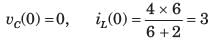
A switch is connected in between a 12 V battery and an uncharged capacitor and a 1 KΩ resistor. At the time instant when the switch is closed, the voltage across the capacitor is:- a)6 V
- b)12 V
- c)0 V
- d)24 V
Correct answer is option 'C'. Can you explain this answer?
A switch is connected in between a 12 V battery and an uncharged capacitor and a 1 KΩ resistor. At the time instant when the switch is closed, the voltage across the capacitor is:
a)
6 V
b)
12 V
c)
0 V
d)
24 V
| | Ameya Nambiar answered |
Ω resistor, as shown in the circuit below:
Battery (+12V) ---[Switch]--- [Capacitor] ---[Resistor]--- Ground
When the switch is closed, the capacitor begins to charge. The time constant of this RC circuit is given by the product of the resistance and the capacitance (RC). In this case, the time constant is 1KΩ * C, where C is the capacitance in farads.
The time constant determines how quickly the capacitor charges. Specifically, it is the time it takes for the capacitor to charge to approximately 63.2% of its final voltage.
If we want to calculate the time it takes for the capacitor to charge to 99% of its final voltage, we can use the formula:
t = -RC * ln(1 - 0.99)
In this case, the final voltage is 12V, so we can plug in the values:
t = -1KΩ * C * ln(1 - 0.99)
To calculate the time it takes for the capacitor to charge to 99% of its final voltage, we need to know the capacitance value. Can you provide the capacitance value?
Inductive load of resistance 20 Ω and inductance 0.1 H is connected in series and switched on to an AC voltage of V = 100 sin(200 t + α). Find the angle α such that there is no transients?- a)45°
- b)60°
- c)30°
- d)75°
Correct answer is option 'A'. Can you explain this answer?
Inductive load of resistance 20 Ω and inductance 0.1 H is connected in series and switched on to an AC voltage of V = 100 sin(200 t + α). Find the angle α such that there is no transients?
a)
45°
b)
60°
c)
30°
d)
75°
| | Pooja Patel answered |
Concept:
For RL load, θ = tan-1 (ωL/R) and,
The condition for transient free response is, θ - α = 0 ⇒ θ = α
Calculation:
V = 100 sin (200t + α)
R = 20Ω, L = 0.1 H
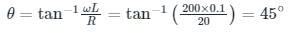 ⇒ α = 45°
The network function (s2 + 8s +15)/(s2 + 6s + 8) is- a)RL admittance
- b)RC admittance
- c)LC admittance
- d)All of the mentioned
Correct answer is option 'A'. Can you explain this answer?
The network function (s2 + 8s +15)/(s2 + 6s + 8) is
a)
RL admittance
b)
RC admittance
c)
LC admittance
d)
All of the mentioned
 | Machine Experts answered |
The singularity nearest to origin is a pole. So it may be a RL admittance or RC impedance function.
The network function (3s2 + 8s)/(s + 1)(s + 3) represents- a)RC impedance
- b)RL impedance
- c)LC impedance
- d)None of the mentioned
Correct answer is option 'C'. Can you explain this answer?
The network function (3s2 + 8s)/(s + 1)(s + 3) represents
a)
RC impedance
b)
RL impedance
c)
LC impedance
d)
None of the mentioned
 | Vertex Academy answered |
The singularity nearest to origin is a zero. So it may be RL impedance or RC admittance function. Because of (D) option it is required to check that it is a valid RC admittance function. The poles and zeros interlace along the negative real axis. The residue of Yrc(s)/s is positive.
The unit step response of a second order system is = 1-e-5t-5te-5t . Consider the following statements:
1. The under damped natural frequency is 5 rad/s.
2. The damping ratio is 1.
3. The impulse response is 25te-5t.
Which of the statements given above are correct?- a)Only 1 and 2
- b)Only 2 and 3
- c)Only 1 and 3
- d)1,2 and 3
Correct answer is option 'D'. Can you explain this answer?
The unit step response of a second order system is = 1-e-5t-5te-5t . Consider the following statements:
1. The under damped natural frequency is 5 rad/s.
2. The damping ratio is 1.
3. The impulse response is 25te-5t.
Which of the statements given above are correct?
1. The under damped natural frequency is 5 rad/s.
2. The damping ratio is 1.
3. The impulse response is 25te-5t.
Which of the statements given above are correct?
a)
Only 1 and 2
b)
Only 2 and 3
c)
Only 1 and 3
d)
1,2 and 3
| | Srestha Gupta answered |
Explanation:
The given unit step response of a second-order system is:
y(t) = 1 - e^(-5t) - 5t * e^(-5t)
To analyze the system, we need to find the natural frequency and the damping ratio.
1. The underdamped natural frequency is 5 rad/s:
To find the natural frequency, we need to find the coefficient of the exponential term in the unit step response. In this case, the coefficient is -5.
Natural frequency (ωn) = sqrt(coefficient) = sqrt(-5) = √5
So, the given statement is correct.
2. The damping ratio is 1:
To find the damping ratio, we need to find the coefficient of the linear term in the unit step response. In this case, the coefficient is -5t.
The damping ratio (ζ) is given by the formula:
ζ = coefficient / (2 * natural frequency) = (-5) / (2 * √5) = -√5 / 2
The given statement is incorrect. The damping ratio is not 1.
3. The impulse response is 25te^(-5t):
To find the impulse response, we need to differentiate the unit step response with respect to time.
Differentiating the unit step response, we get:
y'(t) = 5e^(-5t) - 5e^(-5t) - 5te^(-5t) + 25te^(-5t)
Simplifying, we get:
y'(t) = 5te^(-5t)
Comparing this with the given impulse response, we can see that they are the same.
So, the given statement is correct.
Therefore, the correct statements are:
1. The underdamped natural frequency is 5 rad/s.
3. The impulse response is 25te^(-5t).
Hence, the correct answer is option D) 1, 2, and 3.
For the system 2/s+1, the approximate time taken for a step response to reach 98% of its final value is:- a)1s
- b)2s
- c)4s
- d)8s
Correct answer is option 'C'. Can you explain this answer?
For the system 2/s+1, the approximate time taken for a step response to reach 98% of its final value is:
a)
1s
b)
2s
c)
4s
d)
8s
| | Pooja Patel answered |
C(s)/R(s) = 2/s+1
R(s) = 1/s (step input)
C(s) = 2/s(s+1)
c(t) = 2[1-e-t]
1.96 = 2[1-e-T]
T= 4sec.
R(s) = 1/s (step input)
C(s) = 2/s(s+1)
c(t) = 2[1-e-t]
1.96 = 2[1-e-T]
T= 4sec.
The network function s^2 + 10s + 24/s2 + 8s + 15 represents- a)RC impedance
- b)RL impedance
- c)LC impedance
- d)None of the mentioned
Correct answer is option 'D'. Can you explain this answer?
The network function s^2 + 10s + 24/s2 + 8s + 15 represents
a)
RC impedance
b)
RL impedance
c)
LC impedance
d)
None of the mentioned
| | Ritika Mukherjee answered |
The given network function is s^2 + 10s + 24/s^2 + 8s + 15. This represents neither an RC impedance nor an RL impedance nor an LC impedance. Let's analyze the given network function in detail to understand why it does not represent any of these impedances.
1. RC Impedance:
An RC impedance is represented by a transfer function in the form of 1/(RCs + 1), where R is the resistance and C is the capacitance. In the given network function, we do not have a term in the form of RCs, so it cannot represent an RC impedance.
2. RL Impedance:
An RL impedance is represented by a transfer function in the form of RL/(RLs + 1), where R is the resistance and L is the inductance. Similarly, in the given network function, we do not have a term in the form of RLs, so it cannot represent an RL impedance.
3. LC Impedance:
An LC impedance is represented by a transfer function in the form of 1/(LCs^2 + RCs + 1), where L is the inductance, C is the capacitance, and R is the resistance. In the given network function, we do not have a term in the form of LCs^2, so it cannot represent an LC impedance.
4. None of the mentioned:
Based on the analysis above, we can conclude that the given network function does not fit into any of the mentioned categories, i.e., RC impedance, RL impedance, or LC impedance. Therefore, the correct answer is option 'D' - None of the mentioned.
In summary, the given network function does not represent any of the mentioned impedances (RC, RL, or LC). It is important to understand the different forms of transfer functions for these impedances to accurately identify and categorize them.
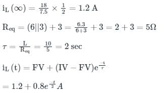
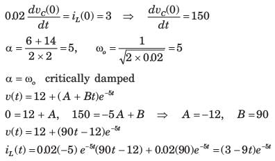
In the circuit shown in the figure, the switch s open for a long time. It is closed at t=0 For t>0 the current flowing through the inductor will be given by
- a)1.2+0.8 e−2(t)
- b)2+0.8 e−t(0.5)
- c)1.2−0.8 e−t/0.25
- d)1.2−0.8 e−t/(2)
Correct answer is option 'D'. Can you explain this answer?
In the circuit shown in the figure, the switch s open for a long time. It is closed at t=0 For t>0 the current flowing through the inductor will be given by
a)
1.2+0.8 e−2(t)
b)
2+0.8 e−t(0.5)
c)
1.2−0.8 e−t/0.25
d)
1.2−0.8 e−t/(2)
| | Pooja Patel answered |
For t < 0,S is open and network is in steady state so the inductor acts like a short circuit.
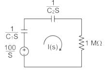
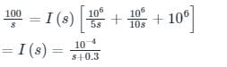
In the circuit shown, the voltage VIN(t) is described by: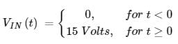 where t is in seconds. The time (in seconds) at which the current I in the circuit will reach the value 2 Amperes is ________.
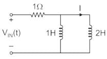
Correct answer is between '0.3,0.4'. Can you explain this answer?
In the circuit shown, the voltage VIN(t) is described by:
where t is in seconds. The time (in seconds) at which the current I in the circuit will reach the value 2 Amperes is ________.
| | Cstoppers Instructors answered |
Concept:
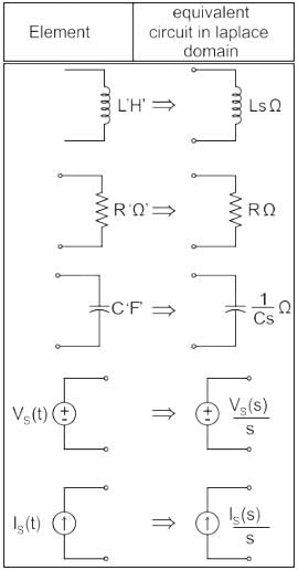
Calculation:
Taking Laplace to transform with given conditions
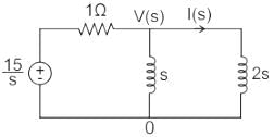
Applying KCL at V(s) node:
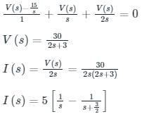
Taking the inverse Laplace transform, we get:
i(t) = 5(1 – e-3t/2)
Given, at t = t0
i = 2 A
2 = 5 (1 – e-3t/2)
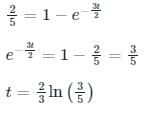
t = 0.3405 sec
The network function (s + 1)(s + 4)/s(s + 2)(s + 5) represents- a)RC impedance
- b)RL impedance
- c)LC impedance
- d)All of the mentioned
Correct answer is option 'B'. Can you explain this answer?
The network function (s + 1)(s + 4)/s(s + 2)(s + 5) represents
a)
RC impedance
b)
RL impedance
c)
LC impedance
d)
All of the mentioned
| | Machine Experts answered |
The singularity nearest to origin is a pole. So it may be RC impedance or RL admittance function.
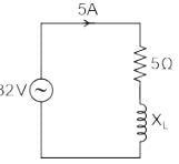
Calculate the peak value of the source voltage (in V) if the root-mean square voltage across the resistor and inductor in a series RL circuit is 13 V and 12 V, respectively. - a)1
- b)17.68
- c)25
- d)3
Correct answer is option 'C'. Can you explain this answer?
Calculate the peak value of the source voltage (in V) if the root-mean square voltage across the resistor and inductor in a series RL circuit is 13 V and 12 V, respectively.
a)
1
b)
17.68
c)
25
d)
3
| | Pooja Patel answered |
Concept:
Source voltage RMS value of a series RL circuit will be;
Vrms = √(VR2 + VL2)
Where;
Vrms → Source voltage in RMS.
VR → Voltage across resistance in RMS.
VL → Voltage across inductor in RMS.
RMS voltage = Peak voltage/√(2)
Calculation:
Given;
VR = 13 V
VL = 12 V
Vrms = √(VR2 + VL2) = √(132 + 122) = 17.69
Peak value of the source voltage = Vrms × √2 = 25.01 V ≈ 25 V
The peak percentage overshoot of the closed loop system is :- a)5.0%
- b)10.0%
- c)16.3%
- d)1.63%
Correct answer is option 'C'. Can you explain this answer?
The peak percentage overshoot of the closed loop system is :
a)
5.0%
b)
10.0%
c)
16.3%
d)
1.63%
| | Pooja Patel answered |
C(s)/R(s) = 1/s2+s+1
C(s)/R(s) = w/ws2 + 2Gws + w2
Compare both the equations,
w = 1 rad/sec
2Gw = 1
Mp = 16.3 %
C(s)/R(s) = w/ws2 + 2Gws + w2
Compare both the equations,
w = 1 rad/sec
2Gw = 1
Mp = 16.3 %
An RL circuit has a resistance of 3 ohms and a reactance of 4 ohms, the impedance of the circuit is- a)5 ohms
- b)7 ohms
- c)1 ohm
- d)1.33 ohms
Correct answer is option 'A'. Can you explain this answer?
An RL circuit has a resistance of 3 ohms and a reactance of 4 ohms, the impedance of the circuit is
a)
5 ohms
b)
7 ohms
c)
1 ohm
d)
1.33 ohms
| | Pooja Patel answered |
Concept:
For a series RL circuit, the net impedance is given by:
Z = R + j (XL)
XL = Inductive Reactance given by:
XL = ωL
The magnitude of the impedance is:
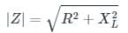
Calculation:
With R = 3 Ω and XL = 4 Ω, we get:
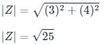
|Z| = 5 Ω
The current response of a network to a unit step input is Io(s) = 10(s + 2)/s(s2 + 11s + 30). The response is- a)Under damped
- b)Over damped
- c)Critically damped
- d)None of the mentioned
Correct answer is option 'B'. Can you explain this answer?
The current response of a network to a unit step input is Io(s) = 10(s + 2)/s(s2 + 11s + 30). The response is
a)
Under damped
b)
Over damped
c)
Critically damped
d)
None of the mentioned
| | Vibhor Goyal answered |
The roots are real and unequal (-6, -5) for the characteristic equation. Hence it is over damped.
If initial voltage retained by the capacitor C1 is 100 V and C2 is zero, the switch k is closed at t = 0, the voltage drop across capacitor C1 in steady state is ________ V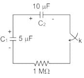
Correct answer is between '33,33.5'. Can you explain this answer?
If initial voltage retained by the capacitor C1 is 100 V and C2 is zero, the switch k is closed at t = 0, the voltage drop across capacitor C1 in steady state is ________ V
| | Cstoppers Instructors answered |
The circuit after the switch is closed is given in the s-domain in the below figure
The voltage drop across capacitor C1 is
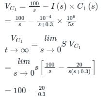
= 33.33 V
The network shown in the figure given below reaches a steady state with the switch K in position a. At t = 0, the switch is moved from a to b by a make-before-break mechanism. Assume the initial current in 2 H inductors as zero. What is the current in 1 H inductor at t = 0+and t = ∞, respectively?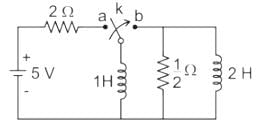
- a)1 A and 0 A
- b)2.5 A and 0 A
- c)1 A and 2.5 A
- d)2.5 A and 2.5 A
Correct answer is option 'B'. Can you explain this answer?
The network shown in the figure given below reaches a steady state with the switch K in position a. At t = 0, the switch is moved from a to b by a make-before-break mechanism. Assume the initial current in 2 H inductors as zero. What is the current in 1 H inductor at t = 0+and t = ∞, respectively?
a)
1 A and 0 A
b)
2.5 A and 0 A
c)
1 A and 2.5 A
d)
2.5 A and 2.5 A
 | Pioneer Academy answered |
Before t = 0 the circuit is
I = 5/2 = 2.5 A
As t → ∞ the current tends to zero, since no power source is present in the circuit, the power stored inductor is dissipated through the resistor.
The network function (s2 + 4s)/(s + 1)(s + 2)(s + 3) represents- a)RC impedance
- b)RL impedance
- c)LC impedance
- d)None of the mentioned
Correct answer is option 'D'. Can you explain this answer?
The network function (s2 + 4s)/(s + 1)(s + 2)(s + 3) represents
a)
RC impedance
b)
RL impedance
c)
LC impedance
d)
None of the mentioned
 | Crack Gate answered |
Poles and zero does not interlace on negative real axis so it is not a immittance function.
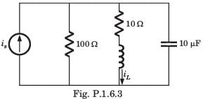
In the figure shown, the ideal switch has been open for a long time.If it is closed at t = 0, then the magnitude of the current (in mA) through the 4kΩ resistor at t = 0+ is _______.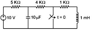
Correct answer is between '1.2,1.3'. Can you explain this answer?
In the figure shown, the ideal switch has been open for a long time.
If it is closed at t = 0, then the magnitude of the current (in mA) through the 4kΩ resistor at t = 0+ is _______.
| | Naroj Boda answered |
Concept:
Under steady-state:
- When a capacitor, is present with a D.C supply, it behaves as an open circuit.
- When an inductor is present with D.C supply, it behaves as a short circuit
At t = 0+ :
Inductor replace with current source IL (0+) = IL (0-)
The inductor does NOT allow the sudden change in current”
The capacitor is replaced with the voltage source
Vc (0+) = Vc (0-)
The capacitor does NOT allow the sudden change in voltage.
Calculation:
The circuit at t = 0-
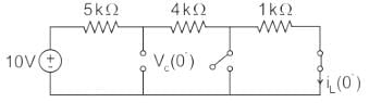
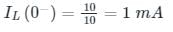
Vc (0-) = 5 V
Circuit at t = 0+
 I = 5/4 = 1.25mA
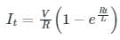
Time constant in an R-L circuit is defined as the time taken by the current to become- a)36.8% of the final value
- b)36.8% of the initial value
- c)63.2% of the final value
- d)None of these
Correct answer is option 'C'. Can you explain this answer?
Time constant in an R-L circuit is defined as the time taken by the current to become
a)
36.8% of the final value
b)
36.8% of the initial value
c)
63.2% of the final value
d)
None of these
| | Maulik Chatterjee answered |
Time Constant in an R-L circuit refers to the time taken by the current to reach approximately 63.2% of its final value after a change in voltage or current is applied to the circuit.
The time constant is determined by the values of resistance (R) and inductance (L) in the circuit. It is denoted by the symbol τ (tau) and is calculated using the formula:
τ = L / R
where:
τ = time constant
L = inductance in henries (H)
R = resistance in ohms (Ω)
Explanation:
To understand why the time constant represents 63.2% of the final value, we need to consider the behavior of an R-L circuit when a voltage or current is applied.
- Initially, when a change in voltage or current is applied, the current in an inductor (L) cannot change instantaneously. It builds up gradually.
- As time progresses, the current increases, but it takes a certain amount of time for the current to reach its maximum value.
- The time constant represents the time it takes for the current to reach 63.2% of its final value.
- After one time constant (τ), the current in the circuit is approximately 63.2% of the final value.
- It takes multiple time constants for the current to reach its final value. However, the majority of the change occurs within the first few time constants.
In other words, the time constant is a measure of the rate at which the current in an R-L circuit approaches its final value. It indicates how quickly the current rises when a voltage or current is applied and how long it takes for the current to settle at its final value.
Hence, the correct answer is option C: 63.2% of the final value.
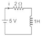
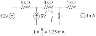
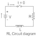
A series RL circuit (as shown in fig) has a constant voltage V = 60 V applied at t = 0. Determine the current flowing through the inductor.
- a)(1 – e-2t)
- b)2(1 – e-2t)
- c)2(e2t)
- d)e-2t
Correct answer is option 'B'. Can you explain this answer?
A series RL circuit (as shown in fig) has a constant voltage V = 60 V applied at t = 0. Determine the current flowing through the inductor.
a)
(1 – e-2t)
b)
2(1 – e-2t)
c)
2(e2t)
d)
e-2t
| | Cstoppers Instructors answered |
The expression of current in a series RL circuit is:

V = 60 V, R = 30, L = 15 H
Current through the inductor is,
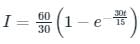
⇒ I = 2(1 – e-2t)
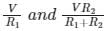
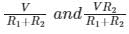
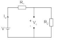
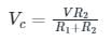
In the circuit shown in the figure, the switch S is closed at time t = 0. The supply current at t = 0+ and the capacitor voltage at t → ∞ are, respectively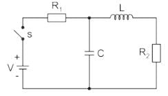
- a)0 and V
- b)
- c)
- d)VR1 and V
Correct answer is option 'B'. Can you explain this answer?
In the circuit shown in the figure, the switch S is closed at time t = 0. The supply current at t = 0+ and the capacitor voltage at t → ∞ are, respectively
a)
0 and V
b)
c)
d)
VR1 and V
| | Luminary Institute answered |
The switch s is closed at time, t = 0
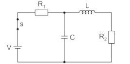
At, t = 0+, the capacitor is short circuited and inductor is open circuited. Now circuit will become
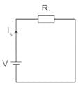

At, t = ∞, the capacitor is open circuited and inductor is short circuited. Now the circuit will become
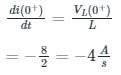
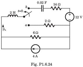
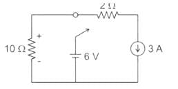
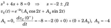
For the circuit shown in the figure, the value of  is _____ (in A/s)
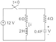
Correct answer is '-4'. Can you explain this answer?
For the circuit shown in the figure, the value of is _____ (in A/s)
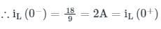
is _____ (in A/s)| | Luminary Institute answered |
At t = 0-, the circuit is as shown below.
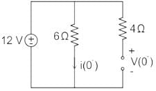
i(0−) = 12 / 6 = 2A
V(0-) = 12 V
The inductor doesn’t allow the sudden change in current.
I(0+) = i(0-) = 2 A
Capacitor doesn’t allow the sudden change in voltage.
V(0-) = V(0+) = 12 V
At t = 0+, the circuit becomes,
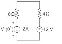
By applying KVL,
-12 + 4(2) + 6(2) + VL(0+) = 0
VL(0+) = -8 V
Since 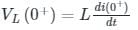
Assertion (A.: It is observed that step function is first derivative of a ramp function and impulse function is first derivative of a step function.
Reason (R): From the derived time response expression it is concluded that the output time response also follows the same sequence as that of input functions.- a)Both A and R are true and R is the correct explanation of A
- b)Both A and R are true but R is not correct explanation of A
- c)Both A is True but R is false
- d)Both A is False but R is true
Correct answer is option 'B'. Can you explain this answer?
Assertion (A.: It is observed that step function is first derivative of a ramp function and impulse function is first derivative of a step function.
Reason (R): From the derived time response expression it is concluded that the output time response also follows the same sequence as that of input functions.
Reason (R): From the derived time response expression it is concluded that the output time response also follows the same sequence as that of input functions.
a)
Both A and R are true and R is the correct explanation of A
b)
Both A and R are true but R is not correct explanation of A
c)
Both A is True but R is false
d)
Both A is False but R is true
| | Partho Saha answered |
Understanding the Assertion and Reason
The assertion (A) states that a step function is the first derivative of a ramp function, and an impulse function is the first derivative of a step function. This statement is indeed true in the context of signal processing.
Key Points of Assertion (A):
- Ramp Function: A ramp function increases linearly over time. Its derivative represents the rate of change.
- Step Function: The step function is constant (zero) until a specific point, where it jumps to a value. The derivative of a ramp function is a step function, indicating an instantaneous change.
- Impulse Function: An impulse function is a theoretical function that represents an instantaneous spike in value. The derivative of a step function, which changes at a single point, is an impulse function.
Examining the Reason (R)
The reason (R) posits that the output time response follows the same sequence as that of the input functions based on the derived time response expression. This statement is also true but does not directly explain the assertion.
Key Points of Reason (R):
- Output Time Response: It is derived from the system's response to various input functions.
- Sequence of Functions: While the time response does follow the sequence of input functions, this does not clarify why the relationships between ramp, step, and impulse functions exist.
Conclusion
- Correctness of A and R: Both A and R are true statements. However, R does not explain A adequately.
- Option B: Thus, the correct answer is option 'B': Both A and R are true, but R is not the correct explanation of A.
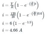
A series RL circuit having a resistance of 20 Ω and inductance of 8 H is connected to a DC voltage source of 120 V at t = 0. The current in the circuit at t = 0.6 sec is- a)0 A
- b)2.33 A
- c)4.66 A
- d)1 A
Correct answer is option 'C'. Can you explain this answer?
A series RL circuit having a resistance of 20 Ω and inductance of 8 H is connected to a DC voltage source of 120 V at t = 0. The current in the circuit at t = 0.6 sec is
a)
0 A
b)
2.33 A
c)
4.66 A
d)
1 A
| | Pooja Patel answered |
Concept:
The Series R-L circuit with DC source is shown below as.
Formula:
The voltage across the resistor is
VR = i.R
The voltage across the Inductor is
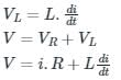
The formula for alternating current passes through the R-L circuit is
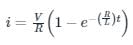
Calculation:
Calculate the power factor of a series RL circuit having the conductance of 30 Siemens and the susceptance of 40 Siemens. - a)0.2
- b)0.4
- c)0.6
- d)0.8
Correct answer is option 'C'. Can you explain this answer?
Calculate the power factor of a series RL circuit having the conductance of 30 Siemens and the susceptance of 40 Siemens.
a)
0.2
b)
0.4
c)
0.6
d)
0.8
| | Devansh Das answered |
To calculate the power factor of a series RL circuit, we need to understand the concept of conductance and susceptance.
1. Conductance:
Conductance, denoted by G, is the reciprocal of resistance. It represents the ease with which current can flow through a circuit. The unit of conductance is Siemens (S).
2. Susceptance:
Susceptance, denoted by B, is the reciprocal of reactance. It represents the ease with which an alternating current can flow through a circuit. The unit of susceptance is also Siemens (S).
Given:
Conductance (G) = 30 S
Susceptance (B) = 40 S
Now, the power factor (PF) of a series RL circuit can be calculated using the following formula:
PF = G / √(G^2 + B^2)
Substituting the given values into the formula:
PF = 30 / √(30^2 + 40^2)
= 30 / √(900 + 1600)
= 30 / √(2500)
= 30 / 50
= 0.6
Therefore, the power factor of the series RL circuit is 0.6.
Explanation:
In a series RL circuit, the power factor is determined by the ratio of the conductance to the square root of the sum of the squares of conductance and susceptance. Conductance represents the real or active power component of the circuit, while susceptance represents the reactive power component.
A power factor of 0.6 indicates that the circuit has a combination of both active and reactive power. It implies that the circuit is not purely resistive but has a certain amount of inductive or capacitive reactance.
A higher power factor (closer to 1) indicates a circuit with less reactive power and more active power. A lower power factor (closer to 0) indicates a circuit with more reactive power and less active power.
Therefore, in this case, the power factor is 0.6, indicating that the series RL circuit has both resistive and reactive components.
In the circuit shown below, a step input voltage of magnitude 5 V is applied at node A at time t = 0. If the capacitor has no charge for t < 0, the voltage at node P at t = 6 μs is ________ V. (Answer should be rounded off to two decimal places)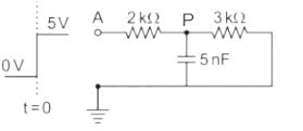
Correct answer is between '1.87,1.91'. Can you explain this answer?
In the circuit shown below, a step input voltage of magnitude 5 V is applied at node A at time t = 0. If the capacitor has no charge for t < 0, the voltage at node P at t = 6 μs is ________ V. (Answer should be rounded off to two decimal places)
| | Cstoppers Instructors answered |
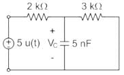
At t ≤ 0, Vc (0) = 0 V
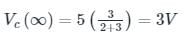
Time constant = τ = Req Ceq
Req = 2kΩ || 3 kΩ = 1.2 kΩ
Ceq = 5 nF
τ = RC = 6 μsec
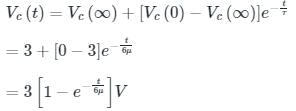
At t = 6 μsec
⇒ Vc(t) = 3 [1 - e-1] = 1.896 V.
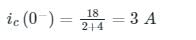
In the circuit shown below, steady state was reached when the switch ‘s’ was open. The switch was closed at t = 0. Then initial value of the current through the capacitor 2C is?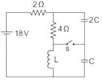
- a)0 A
- b)1 A
- c)2 A
- d)3 A
Correct answer is option 'C'. Can you explain this answer?
In the circuit shown below, steady state was reached when the switch ‘s’ was open. The switch was closed at t = 0. Then initial value of the current through the capacitor 2C is?
a)
0 A
b)
1 A
c)
2 A
d)
3 A
| | Cstoppers Instructors answered |
At steady-state conditions, the capacitor acts as an open circuit, and the inductor acts as a short circuit.
Now considering t = 0-,

Now voltage across 4 Ω resistor is 12 V.
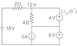
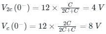
Considering t = 0+
By KCL, 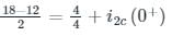
i2c (0+) = 2 A
The initial value of the current through the capacitor 2 C is 2 A.
A first order system and its response to a unit step input are shown in figure below. The system parameters are____________- a)a = 5 and k = 12
- b)a = 10 and k = 5
- c)a = 5 and k = 10
- d)a = 8 and k = 9
Correct answer is option 'C'. Can you explain this answer?
A first order system and its response to a unit step input are shown in figure below. The system parameters are____________
a)
a = 5 and k = 12
b)
a = 10 and k = 5
c)
a = 5 and k = 10
d)
a = 8 and k = 9
| | Pooja Patel answered |
time constant = 0.2 sec.
1/a = 0.2
a = 5
final value =
K/a = 2
K = 10.
1/a = 0.2
a = 5
final value =
K/a = 2
K = 10.
The unit step response of a second-order system with a damping ratio of 0.2 and natural frequency of 5 rad/s is given by:
c(t) = 1 - e^(-0.2t) * (cos(4.9t) + (0.2/0.2) * sin(4.9t))
What is the maximum overshoot in this system?- a)5%
- b)10%
- c)16.3%
- d)20%
Correct answer is option 'D'. Can you explain this answer?
The unit step response of a second-order system with a damping ratio of 0.2 and natural frequency of 5 rad/s is given by:
c(t) = 1 - e^(-0.2t) * (cos(4.9t) + (0.2/0.2) * sin(4.9t))
What is the maximum overshoot in this system?
c(t) = 1 - e^(-0.2t) * (cos(4.9t) + (0.2/0.2) * sin(4.9t))
What is the maximum overshoot in this system?
a)
5%
b)
10%
c)
16.3%
d)
20%
 | EduRev GATE answered |
The maximum overshoot Mp is given by:
Mp = 100 * exp( - (ζ * π) / √(1 - ζ²))
For ζ = 0.2,
Mp ≈ 20%
Mp = 100 * exp( - (ζ * π) / √(1 - ζ²))
For ζ = 0.2,
Mp ≈ 20%
In the circuit shown below, switch S1 and S2 are in open and close position respectively for long time. At t = t0, switch S1 is closed and switch S2 is opened. What would be the current through R1 immediately after the transition of switches?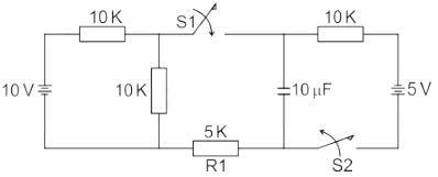
- a)0 mA
- b)1 mA
- c)0.5 mA
- d)2 mA
Correct answer is option 'B'. Can you explain this answer?
In the circuit shown below, switch S1 and S2 are in open and close position respectively for long time. At t = t0, switch S1 is closed and switch S2 is opened. What would be the current through R1 immediately after the transition of switches?
a)
0 mA
b)
1 mA
c)
0.5 mA
d)
2 mA
| | Pioneer Academy answered |
Concept:
A capacitor doesn’t allow a sudden change in voltage, i.e. Vc(0+) = Vc(0-).
Similarly, an inductor doesn’t allow a sudden change in current, i.e. iL(0+) = iL(0-)
Calculation:
The circuit for t = t0- is as shown,
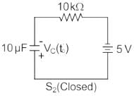
Vc(t0-) = 5V as shown above,
At t = t0+, the circuit will be as shown, in which the capacitor will be at 5V (∵ Vc(0+) = Vc(0-))
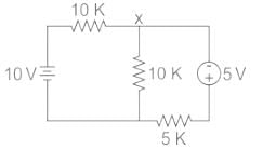
To find the voltage at node ‘x’, we apply KCL to get,
Now the required current through R1 = 5KΩ, immediately after the transition of switches is
In Reciprocity Theorem, which of the following ratios is considered?- a)Voltage to current
- b)Current to current
- c)Voltage to voltage
- d)No ratio is considered
Correct answer is option 'A'. Can you explain this answer?
In Reciprocity Theorem, which of the following ratios is considered?
a)
Voltage to current
b)
Current to current
c)
Voltage to voltage
d)
No ratio is considered
| | Saranya Mishra answered |
Reciprocity Theorem in Electrical Engineering
The Reciprocity Theorem in electrical engineering states that in a linear bilateral network, the ratio of voltage to current at one point in the network is equal to the ratio of current to voltage at another point in the network.
Ratio Considered in Reciprocity Theorem
In the Reciprocity Theorem, the ratio considered is the ratio of voltage to current. This means that the voltage at one point in the network divided by the current at that same point is equal to the current at another point in the network divided by the voltage at that point.
Therefore, the correct answer is option 'A) Voltage to current'.
By understanding and applying the Reciprocity Theorem in electrical network analysis, engineers can simplify calculations and determine the relationship between different points in a network more efficiently.
Overall, the Reciprocity Theorem plays a crucial role in analyzing electrical networks and understanding the interrelationship between voltage and current at different points within the network.
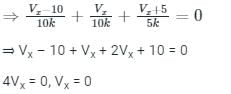
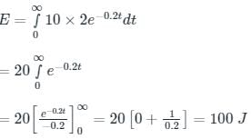
The initial charge in the 1 F capacitor present in the circuit shown is zero. The energy in joules transferred from the DC source until steady state condition is reached equals _________. (Give the answer up to one decimal place.)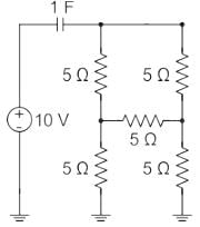
Correct answer is between '99,101'. Can you explain this answer?
The initial charge in the 1 F capacitor present in the circuit shown is zero. The energy in joules transferred from the DC source until steady state condition is reached equals _________. (Give the answer up to one decimal place.)
| | Pioneer Academy answered |
Given circuit diagram:

The above circuit can be redrawn as, (the above circuit forms a balanced bridge condition)
The equivalent resistance of all the 5 Ω resistors is 5 Ω
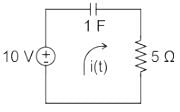
Current in the circuit will be
i(t) = I e-4τ
Time constant τ = RC = 5 secs
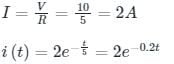
Energy transferred from the DC source,
A valid immittance function is- a)(s + 4)(s + 8)/(s + 2)(s – 5)
- b)s(s + 1)/(s + 2)(s + 5)
- c)s(s + 2)(s + 3)/(s + 1)(s + 4)
- d)s(s + 2)(s + 6)/(s + 1)(s + 4)
Correct answer is option 'D'. Can you explain this answer?
A valid immittance function is
a)
(s + 4)(s + 8)/(s + 2)(s – 5)
b)
s(s + 1)/(s + 2)(s + 5)
c)
s(s + 2)(s + 3)/(s + 1)(s + 4)
d)
s(s + 2)(s + 6)/(s + 1)(s + 4)
| | Machine Experts answered |
a) pole lie on positive real axis
b) poles and zero does not interlace on axis.
c) poles and zero does not interlace on axis.
d) is a valid immittance function.
b) poles and zero does not interlace on axis.
c) poles and zero does not interlace on axis.
d) is a valid immittance function.
A coil takes a current of 5 A when connected to a 25 V DC supply. To obtain the same current with a 50 Hz AC supply, the voltage required was 32 V. Calculate the inductive reactance and power factor of the coil.- a)4 Ω, 0.78 lead
- b)5 Ω, 0.62 lead
- c)4 Ω, 0.78 lag
- d)5 Ω, 0.62 lag
Correct answer is option 'C'. Can you explain this answer?
A coil takes a current of 5 A when connected to a 25 V DC supply. To obtain the same current with a 50 Hz AC supply, the voltage required was 32 V. Calculate the inductive reactance and power factor of the coil.
a)
4 Ω, 0.78 lead
b)
5 Ω, 0.62 lead
c)
4 Ω, 0.78 lag
d)
5 Ω, 0.62 lag
| | Luminary Institute answered |
Concept:- A coil is made up of inductive reactance and Resistance.
i.e. When it is connected to the DC supply, the inductor will act as a short circuit
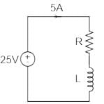
Hence, Resistance of the coil = Ω
For AC supply, the inductor will offer finite reactance that will depend on the frequency of the supply.
i.e, XL = ωL
Now,
Z = V/I = 32/5 = 6.4 Ω
We know that,
Power Factor = R/Z = 5/6.4 = 0.78
And,
X2 = Z2 - R2
Hence,

In a series RL circuit the value of inductance is 1 Henry and resistance is 10 ohms. What is the time constant of the circuit?- a)0.1 sec
- b)1 sec
- c)10 sec
- d)None of the above
Correct answer is option 'A'. Can you explain this answer?
In a series RL circuit the value of inductance is 1 Henry and resistance is 10 ohms. What is the time constant of the circuit?
a)
0.1 sec
b)
1 sec
c)
10 sec
d)
None of the above
| | Luminary Institute answered |
Concept:
We can use Kirchhoff’s Voltage Law, (KVL) to define the individual voltage drops that exist around the circuit and then hopefully use it to give us an expression for the flow of current.
The Time Constant, ( τ ) of the LR series circuit is given as L/R and in which V/R represents the final steady-state current value after five-time constant values.
Calculation:
L = 1 H, R = 10Ω
Time constant = 1/10 = 0.1 sec
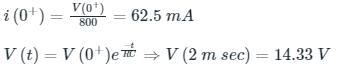
Find i(0+) and V (2 m sec) for the circuit shown below.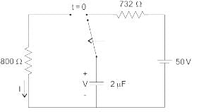
- a)14.33 A, 50 V
- b)62.5 mA, 14.33 V
- c)62.5 mA, 62.5 V
- d)14.33 A, 14.33 V
Correct answer is option 'B'. Can you explain this answer?
Find i(0+) and V (2 m sec) for the circuit shown below.
a)
14.33 A, 50 V
b)
62.5 mA, 14.33 V
c)
62.5 mA, 62.5 V
d)
14.33 A, 14.33 V
| | Luminary Institute answered |
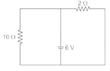
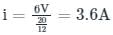
V(0−) = 50 V = V(0+)
For t > 0, RC = 1.6 m sec.
The circuit shown in figure was at steady state for t < 0 with switch at position ‘A’. The switch is thrown to position ‘B’ at time t = 0. The voltage across the 10 ohm resistor at time t = 0+ is ________V.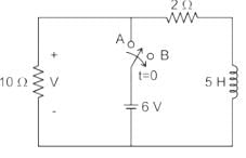
Correct answer is between '-31,-29'. Can you explain this answer?
The circuit shown in figure was at steady state for t < 0 with switch at position ‘A’. The switch is thrown to position ‘B’ at time t = 0. The voltage across the 10 ohm resistor at time t = 0+ is ________V.
| | Cstoppers Instructors answered |
At t < 0 the circuit was in steady state and switch at ‘A’
The current drawn by circuit i
=
=
Current through the inductor IL(0-)
=
=
Immediately after t > 0 the circuit will be the current through Inductor IL(0-) = IL(0+)
at t= 0+
V = IL(0+) × 10Ω
= -3 × 10 = -30V
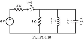
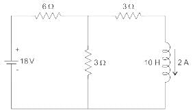
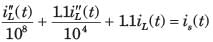
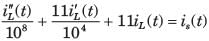
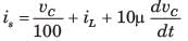
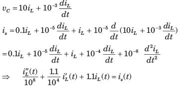
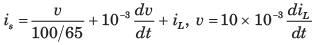
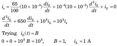
In the circuit shown in fig. P1.6.12–14 all initial condition are zero.
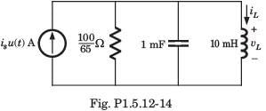
Q. If is (t) = 0.5 A, then iL (t) is- a)0.5 t + 3.25 x 10⁻³ A
- b)2 t - 3250 A
- c)0.5 t - 0.25 x 10⁻³ A
- d)2 t + 3250 A
Correct answer is option 'A'. Can you explain this answer?
In the circuit shown in fig. P1.6.12–14 all initial condition are zero.
Q. If is (t) = 0.5 A, then iL (t) is
Q. If is (t) = 0.5 A, then iL (t) is
a)
0.5 t + 3.25 x 10⁻³ A
b)
2 t - 3250 A
c)
0.5 t - 0.25 x 10⁻³ A
d)
2 t + 3250 A
 | Engineers Adda answered |
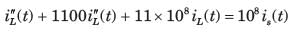
Use the branch relations: the voltage across the parallel branches is v(t) and for the inductor v = L \, di_L/dt. The capacitor current is i_C = C \; dv/dt = C L \; d^2 i_L/dt^2 and the resistor current is i_R = v/R = (L/R) \; di_L/dt. By KCL: i_s = i_R + i_C + i_L. Substituting the expressions gives C L \; d^2 i_L/dt^2 + (L/R) \; d i_L/dt + i_L = i_s. Dividing by L yields the standard ODE: C \; d^2 i_L/dt^2 + (1/R) \; d i_L/dt + (1/L) \; i_L = i_s / L. Substitute the numerical values R = 100/65 Ω, C = 1 mF = 1×10^{-3} F, L = 10 mH = 10×10^{-3} H, and i_s = 0.5 A. Noting 1/R = 0.65 and 1/L = 100, the ODE becomes d^2 i_L/dt^2 + 650 \; d i_L/dt + 100000 \; i_L = 50000. The homogeneous characteristic equation is r^2 + 650 r + 100000 = 0. The discriminant is 650^2 - 4·100000 = 22500, so the roots are r = -250 and r = -400. Thus the general solution is i_L(t) = 0.5 + A e^{-250 t} + B e^{-400 t}, where 0.5 A is the steady-state value found from i_L(∞)=i_s=0.5 A. Apply initial conditions: i_L(0)=0 gives A + B = -0.5. Also v(0)=0 (all initial conditions zero) implies di_L/dt(0)=v(0)/L = 0, which yields -250 A - 400 B = 0. Solving these two equations gives A = -4/3 and B = 5/6. Therefore i_L(t) = 0.5 - (4/3) e^{-250 t} + (5/6) e^{-400 t} A, which matches option A. |

Chapter doubts & questions for Transient Analysis in AC & DC Circuits - 3 Months Preparation for GATE Electrical 2026 is part of Electrical Engineering (EE) exam preparation. The chapters have been prepared according to the Electrical Engineering (EE) exam syllabus. The Chapter doubts & questions, notes, tests & MCQs are made for Electrical Engineering (EE) 2026 Exam. Find important definitions, questions, notes, meanings, examples, exercises, MCQs and online tests here.
Chapter doubts & questions of Transient Analysis in AC & DC Circuits - 3 Months Preparation for GATE Electrical in English & Hindi are available as part of Electrical Engineering (EE) exam. Download more important topics, notes, lectures and mock test series for Electrical Engineering (EE) Exam by signing up for free.
3 Months Preparation for GATE Electrical676 videos|1399 docs|882 tests |