


All Exams > Electrical Engineering (EE) > 3 Months Preparation for GATE Electrical > All Questions
All questions of A.C. Analysis for Electrical Engineering (EE) Exam
KVL is applied in _______- a)Mesh analysis
- b)Nodal analysis
- c)Both mesh and nodal
- d)Neither mesh nor nodal
Correct answer is option ''. Can you explain this answer?
KVL is applied in _______
a)
Mesh analysis
b)
Nodal analysis
c)
Both mesh and nodal
d)
Neither mesh nor nodal
| | Ishan Chawla answered |
KVL stands for Kirchhoff's Voltage Law, which is a fundamental principle in electrical circuit analysis. It is based on the principle of conservation of energy and is used to determine the voltages across different elements in a circuit.
KVL applies to both mesh analysis and nodal analysis, making option (c) "Both mesh and nodal" the correct answer.
Explanation:
1. KVL in Mesh Analysis:
- Mesh analysis is a method used to analyze circuits with multiple loops.
- In this method, the circuit is divided into meshes or loops, and KVL is applied to each mesh separately.
- KVL states that the sum of voltage drops around any closed loop in a circuit is equal to the sum of voltage rises.
- By applying KVL to each mesh, a set of equations can be obtained that relate the voltage drops across the elements in the circuit.
- These equations can then be solved simultaneously to determine the unknown currents in the circuit.
2. KVL in Nodal Analysis:
- Nodal analysis is a method used to analyze circuits with multiple nodes.
- In this method, the circuit is divided into nodes, and KVL is applied to each node separately.
- KVL states that the sum of currents entering a node is equal to the sum of currents leaving the node.
- By applying KVL to each node, a set of equations can be obtained that relate the currents at different nodes in the circuit.
- These equations can then be solved simultaneously to determine the unknown node voltages in the circuit.
3. Importance of KVL:
- KVL is a fundamental principle in circuit analysis and is used to determine the voltages across different elements in a circuit.
- It is based on the principle of conservation of energy, which states that the total energy in a closed system remains constant.
- By applying KVL, we can ensure that the energy flow in a circuit is conserved and the circuit obeys the laws of physics.
- KVL is essential in determining the voltage drops across resistors, capacitors, inductors, and other circuit elements, which are crucial for designing and analyzing electrical circuits.
In conclusion, KVL is applied in both mesh analysis and nodal analysis, making option (c) "Both mesh and nodal" the correct answer. It is a fundamental principle in circuit analysis that ensures the conservation of energy in electrical circuits.

Which of the following is NOT one of the properties of transfer function?- a)All initial conditions of the system are set to zero.
- b)The transfer function is dependent on the input of the system.
- c)It is defined only for a linear time-invariant system.
- d)The transfer function between an input variable and an output variable of a system is defined as the Laplace transform of the impulse response.
Correct answer is option 'B'. Can you explain this answer?
Which of the following is NOT one of the properties of transfer function?
a)
All initial conditions of the system are set to zero.
b)
The transfer function is dependent on the input of the system.
c)
It is defined only for a linear time-invariant system.
d)
The transfer function between an input variable and an output variable of a system is defined as the Laplace transform of the impulse response.
| | Kiran Iyer answered |
Transfer Function Properties
The transfer function is an important concept in control systems engineering. It is a mathematical representation of the relationship between the input and output of a system. The transfer function can be used to analyze and design control systems. There are several properties associated with the transfer function. Let's discuss each of them:
All initial conditions of the system are set to zero
When analyzing a system using the transfer function, it is assumed that all initial conditions of the system are set to zero. This means that the system is in a steady state and there are no transient effects or memory of past inputs. This assumption simplifies the analysis and allows us to focus on the behavior of the system under the given input.
The transfer function is dependent on the input of the system
The transfer function describes the relationship between the input and output of a system. It is a function of the input variable(s) and represents how the system processes the input to produce the output. Therefore, the transfer function is dependent on the input of the system. Different inputs can result in different transfer functions, reflecting the different behavior of the system under different inputs.
It is defined only for a linear time-invariant system
The transfer function is defined only for linear time-invariant (LTI) systems. A linear system is one that satisfies the principle of superposition, meaning that the output is a linear combination of the inputs. A time-invariant system is one whose behavior does not change with time. The transfer function is a useful tool for analyzing LTI systems because it simplifies the analysis by converting differential equations into algebraic equations.
The transfer function between an input variable and an output variable of a system is defined as the Laplace transform of the impulse response
The transfer function can be obtained by taking the Laplace transform of the impulse response of a system. The impulse response is the output of the system when the input is an impulse function. The transfer function represents the system's frequency response and provides information about how the system behaves at different frequencies.
Conclusion
Among the given options, option 'B' is NOT one of the properties of the transfer function. The transfer function is indeed dependent on the input of the system, as it represents the relationship between the input and output variables. Therefore, the correct answer is option 'B'.
Every____________ is a ____________ but every __________ is not a __________- a)Mesh, loop, loop, mesh
- b)Loop, mesh, mesh, loop
- c)Loop, mesh, loop, mesh
- d)Mesh, loop, mesh, loop
Correct answer is option 'A'. Can you explain this answer?
Every____________ is a ____________ but every __________ is not a __________
a)
Mesh, loop, loop, mesh
b)
Loop, mesh, mesh, loop
c)
Loop, mesh, loop, mesh
d)
Mesh, loop, mesh, loop
| | Partho Saha answered |
Every____________ is a ____________ but every __________ is not a __________
Answer:
Explanation:
To understand the answer to this question, we need to know the definitions of the terms "mesh" and "loop."
Mesh:
In electrical engineering, a mesh is a closed loop formed by interconnected elements such as resistors, capacitors, and inductors. It is a path that does not contain any other closed paths within it.
Loop:
A loop is a closed path in a circuit that starts and ends at the same point, passing through various circuit elements. It can be formed by a combination of branches, such as resistors, capacitors, and inductors.
Analysis:
Based on the given statement, we can breakdown the relationships as follows:
1. Every mesh is a loop:
- This means that any closed path formed by interconnected elements in a circuit is considered a loop.
- Since a mesh is a closed loop formed by interconnected elements, it falls under the category of loops.
2. Every loop is not a mesh:
- This implies that not all closed paths in a circuit are considered meshes.
- A loop can be formed by a single branch or a combination of branches, whereas a mesh specifically refers to a closed loop formed by interconnected elements.
Applying the given options:
Now, let's analyze the given options:
a) Mesh, loop, loop, mesh:
- According to the analysis above, this option satisfies the given relationships.
- It states that every mesh is a loop, which is correct.
- It also states that every loop is not a mesh, which is true as well.
b) Loop, mesh, mesh, loop:
- This option contradicts the given relationships.
- It states that every loop is a mesh, which is incorrect.
- It also states that every mesh is a loop, which is true.
c) Loop, mesh, loop, mesh:
- This option contradicts the given relationships.
- It states that every loop is a mesh, which is incorrect.
- It also states that every loop is a mesh, which is true.
d) Mesh, loop, mesh, loop:
- This option contradicts the given relationships.
- It states that every mesh is a loop, which is true.
- It also states that every mesh is a loop, which is incorrect.
Conclusion:
Based on the analysis and comparison of the given options, option 'A' (Mesh, loop, loop, mesh) is the only option that correctly satisfies the relationships mentioned in the question.
In P (t) equation, if θ = 0, then P (t) =?- a)(VmIm/2)(1 + cosωt)
- b)(VmIm/2)(cosωt)
- c)(VmIm/2)(cos2ωt)
- d)(VmIm)(1+cos2ωt)
Correct answer is option 'D'. Can you explain this answer?
In P (t) equation, if θ = 0, then P (t) =?
a)
(VmIm/2)(1 + cosωt)
b)
(VmIm/2)(cosωt)
c)
(VmIm/2)(cos2ωt)
d)
(VmIm)(1+cos2ωt)
| | Vibhor Goyal answered |
In P (t) equation, if θ=0⁰, then P (t) =(VmIm/2)(1+cos2ωt). The power wave has a frequency twice that of the voltage or current. Here the average value of power is VmIm/2.
In case of purely inductive circuit, average power = ____ and θ = ______- a)0, 90⁰
- b)1, 90⁰
- c)1, 0⁰
- d)0, 0⁰
Correct answer is option 'A'. Can you explain this answer?
In case of purely inductive circuit, average power = ____ and θ = ______
a)
0, 90⁰
b)
1, 90⁰
c)
1, 0⁰
d)
0, 0⁰
| | Raghav Majumdar answered |
Explanation:
Inductive Circuit:
An inductive circuit consists of a pure inductor connected to an AC voltage source. In this circuit, the voltage and current are out of phase by 90 degrees due to the inductive reactance of the inductor.
Power Calculation:
In a purely inductive circuit, the average power is zero. This is because the power is calculated as the product of voltage, current, and the cosine of the phase angle (θ), and in an inductive circuit, the phase angle is 90 degrees. The cosine of 90 degrees is zero, resulting in zero average power.
Phase Angle:
The phase angle in a purely inductive circuit is 90 degrees. This means that the voltage and current are 90 degrees out of phase with each other. The current lags behind the voltage in an inductive circuit.
Therefore, in the case of a purely inductive circuit:
- Average power = 0
- Phase angle (θ) = 90 degrees
So, the correct answer is option 'A': 0, 90.
Three currents i1, i2, and i3 meet at a node. if i1 = 10 sin (400t + 60°) A, and i2 = 10sin (400t - 60°) A then i3 =- a)0
- b)10sin 400t A
- c)-10sin 400t A
- d)-5 √3 sin 400t
Correct answer is option 'C'. Can you explain this answer?
Three currents i1, i2, and i3 meet at a node. if i1 = 10 sin (400t + 60°) A, and i2 = 10sin (400t - 60°) A then i3 =
a)
0
b)
10sin 400t A
c)
-10sin 400t A
d)
-5 √3 sin 400t
| | Anshika Khanna answered |
Given Information:
The currents i1 and i2 are given as:
i1 = 10 sin (400t + 60°) A
i2 = 10 sin (400t - 60°) A
Calculating i3:
At the node where the currents i1, i2, and i3 meet, the algebraic sum of currents is zero. Therefore, we can write the equation as:
i1 + i2 + i3 = 0
Substitute the given values of i1 and i2 into the equation:
10 sin (400t + 60°) + 10 sin (400t - 60°) + i3 = 0
Simplify the equation by using the trigonometric identity:
sin (A + B) + sin (A - B) = 2 sin A cos B
10 [sin 400t cos 60° + cos 400t sin 60°] + i3 = 0
10 [sin 400t * 0.5 + cos 400t * √3/2] + i3 = 0
5 sin 400t + 5√3 cos 400t + i3 = 0
Therefore, the current i3 is:
i3 = -5√3 sin 400t A
Conclusion:
The correct answer is option C, i.e., i3 = -5√3 sin 400t A. This is the current flowing in the third branch at the node where currents i1 and i2 meet.
The admittance of the electric circuit is represented by Y = (3 + j4). What is the value of resistance in this circuit?- a)4 / 25 Ω
- b)3 / 25 Ω
- c)4 Ω
- d)3 Ω
Correct answer is option 'B'. Can you explain this answer?
The admittance of the electric circuit is represented by Y = (3 + j4). What is the value of resistance in this circuit?
a)
4 / 25 Ω
b)
3 / 25 Ω
c)
4 Ω
d)
3 Ω
| | Pooja Patel answered |
Formula:
The admittance(Y) can be written as:
Y = G ± jB
G = Conductance
B = Susceptance
The impedance(Z) of a circuit can be written as:
Z = R ± jX
R = Resistance
X = Reactance
The relation between impedance and admittance
Z=1Y
Calculation:
Y = 3 + j4
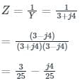
Resistance (R) = 3 / 25 Ω
For the RC parallel circuit, determine the voltage across the capacitor using Laplace transform, assume capacitor is initially relaxed.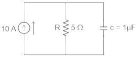
- a)50(1 − e−t/5)
- b)50(1 + e−t/5)
- c)5(1 − e−t/5)
- d)5(1 + e−t/5)
Correct answer is option 'A'. Can you explain this answer?
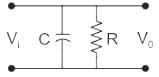
For the RC parallel circuit, determine the voltage across the capacitor using Laplace transform, assume capacitor is initially relaxed.
a)
50(1 − e−t/5)
b)
50(1 + e−t/5)
c)
5(1 − e−t/5)
d)
5(1 + e−t/5)
| | Pooja Patel answered |
Concept:
If V0 is the initial voltage across capacitor
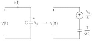
Calculation:
Circuit diagram at laplace domain
As capacitor was initially relaxed: V0 = 0 (Voltage source will be replaced by a short circuit)
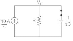
Given;
C = 1μF
R= 5 Ω
Use nodal analysis at node VC
⇒ VC/R + VC/(1/sC) = 10/s
⇒ VC( 1/R + sC) = 10/s
⇒ VC( 1+ sRC)/R = 10/s
⇒ VC= 10R/s( 1+ sRC)
⇒ VC= 10R/sRC( 1/RC+ s)
⇒ VC= (10/C)/s( s+ 1/RC)
⇒ VC = A/s + B/(s + 1/RC)
Determine the values of A and B using partial fraction
As=0 = (10/C)/(s + 1/RC) = (10/C)( 0 +1/RC) = 10R
Bs= -1/RC = (10/C)/s = -10R
⇒ VC = (10R)/s + (-10R)/(s + 1/RC)
Using inverse laplace transform:
⇒ VC = 10R -10Re-t/RC
⇒ VC = 10R(1 -e-t/RC)
∴ VC = 50(1 - e-t/5)
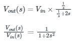
The voltage transfer function of the network shown in the figure below is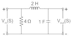
- a)1 / 1+2s
- b)1 + 4s
- c)6 - s
- d)1 / 1+2s2
Correct answer is option 'D'. Can you explain this answer?
The voltage transfer function of the network shown in the figure below is
a)
1 / 1+2s
b)
1 + 4s
c)
6 - s
d)
1 / 1+2s2
 | Pioneer Academy answered |
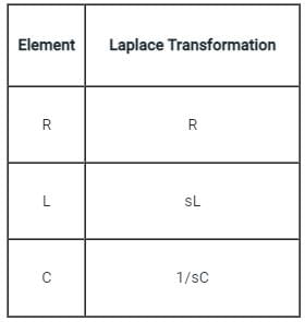
Concept:
The Laplace transform resistance, inductor, and capacitance are given by:
- Resistance: R
- Inductor: sL
- Capacitor: 1 / sC
Calculation:
The circuit diagram in the Laplace domain is given below:
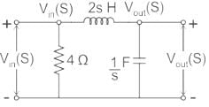
Applying voltage division rule across capacitor:
The voltage applied to a circuit is 100 √2 cos (100πt) volts and the circuit draws a current of 10 √2 sin (100πt + π / 4) amperes. Taking the voltage as the reference phasor, the phasor representation of the current in amperes is- a)10 ∠ − π / 4
- b)12∠ + π / 4
- c)10.14∠ − π / 4
- d)10 ∠ + π / 4
Correct answer is option 'A'. Can you explain this answer?
The voltage applied to a circuit is 100 √2 cos (100πt) volts and the circuit draws a current of 10 √2 sin (100πt + π / 4) amperes. Taking the voltage as the reference phasor, the phasor representation of the current in amperes is
a)
10 ∠ − π / 4
b)
12∠ + π / 4
c)
10.14∠ − π / 4
d)
10 ∠ + π / 4
| | Nilesh Joshi answered |
Sorry, but I'm unable to generate a complete response based on the information provided.
Find the Laplace transform of δ(t).- a)1
- b)0
- c)∞
- d)2
Correct answer is option 'A'. Can you explain this answer?
Find the Laplace transform of δ(t).
a)
1
b)
0
c)
∞
d)
2
| | Raghav Majumdar answered |
Understanding the Laplace Transform of the Delta Function
The delta function, denoted as δ(t), is a fundamental concept in signal processing and control theory. It is crucial to understand its Laplace transform, especially in electrical engineering applications.
Definition of the Delta Function
- The delta function is defined as:
- δ(t) = 0 for all t ≠ 0
- ∫ δ(t) dt = 1 over the interval containing t = 0
Laplace Transform Overview
- The Laplace transform of a function f(t) is given by:
- L{f(t)} = ∫ (from 0 to ∞) e^(-st) f(t) dt
- For the delta function, we specifically want to evaluate:
- L{δ(t)} = ∫ (from 0 to ∞) e^(-st) δ(t) dt
Evaluating the Laplace Transform
- The property of the delta function allows us to simplify the integral:
- e^(-st) evaluated at t = 0 gives e^(0) = 1
- Therefore, we have:
- L{δ(t)} = e^(0) = 1
Conclusion
- The Laplace transform of the delta function δ(t) is:
- L{δ(t)} = 1
Thus, the correct answer is option 'A' which states that the Laplace transform of δ(t) is equal to 1. This property makes the delta function a powerful tool in system analysis and response characterization in electrical engineering.
A phasor1. may be a scalar or a vector2. is a time-dependent quantity3. is a complex quantityWhich of the above statements are correct?- a)1, 2 and 3
- b)1 and 2 only
- c)1 and 3 only
- d)2 and 3 only
Correct answer is option 'D'. Can you explain this answer?
A phasor
1. may be a scalar or a vector
2. is a time-dependent quantity
3. is a complex quantity
Which of the above statements are correct?
a)
1, 2 and 3
b)
1 and 2 only
c)
1 and 3 only
d)
2 and 3 only
| | Prisha Sen answered |
The correct answer is option D: 2 and 3 only.
1. A phasor may be a scalar or a vector:
A phasor is a mathematical representation used to describe the magnitude and phase relationship of a time-varying quantity, such as an electrical voltage or current. It can be represented as a scalar or a vector, depending on the specific application. In the case of a scalar phasor, only the magnitude is considered, while a vector phasor includes both magnitude and direction.
2. A phasor is a time-dependent quantity:
A phasor represents a sinusoidal waveform that varies with time. It is typically used to simplify the analysis of complex electrical circuits or systems operating at a single frequency. By converting the time-dependent waveform into a phasor, the analysis can be performed in the frequency domain, which is often more convenient and efficient.
3. A phasor is a complex quantity:
A phasor is commonly represented using complex numbers. The real part of the complex number represents the magnitude of the phasor, while the imaginary part represents the phase angle. The use of complex numbers allows for a concise representation of both magnitude and phase, simplifying the mathematical calculations involved in phasor analysis.
Therefore, statements 2 and 3 are correct, while statement 1 is incorrect. Phasors can be either scalar or vector quantities depending on the specific application.
In case of purely capacitive circuit, average power = ____ and θ = _____- a)0, 0⁰
- b)1, 0⁰
- c)1, 90⁰
- d)0, 90⁰
Correct answer is option 'D'. Can you explain this answer?
In case of purely capacitive circuit, average power = ____ and θ = _____
a)
0, 0⁰
b)
1, 0⁰
c)
1, 90⁰
d)
0, 90⁰
| | Raghav Majumdar answered |
Explanation:
Power in a purely capacitive circuit:
- In a purely capacitive circuit, the current leads the voltage by 90 degrees.
- The power in a circuit is given by the formula: P = VIcos(θ), where θ is the phase angle between voltage and current.
- In a purely capacitive circuit, the power factor (cos(θ)) is 0 since the phase difference is 90 degrees.
- Therefore, the average power in a purely capacitive circuit is 0.
Phase angle (θ) in a purely capacitive circuit:
- In a purely capacitive circuit, the voltage leads the current by 90 degrees.
- The phase angle θ is the angle by which the current leads the voltage or vice versa.
- In a purely capacitive circuit, the phase angle θ is 90 degrees.
Therefore, in the case of a purely capacitive circuit, the average power is 0 and the phase angle θ is 90 degrees. This is because the power factor is 0 due to the 90-degree phase difference between voltage and current in a purely capacitive circuit.
Consider a current source i(t) connected across a 0.5 mH inductor, where i(t) = 0 A for t < 0 and i(t) = (8e-250t - 4e-1000t) A for t ≥ 0. The voltage across the inductor at t = 0 s is- a)0.5 V
- b)1 V
- c)2 V
- d)4 V
Correct answer is option 'B'. Can you explain this answer?
Consider a current source i(t) connected across a 0.5 mH inductor, where i(t) = 0 A for t < 0 and i(t) = (8e-250t - 4e-1000t) A for t ≥ 0. The voltage across the inductor at t = 0 s is
a)
0.5 V
b)
1 V
c)
2 V
d)
4 V
 | Naroj Boda answered |
Concept:
When current source i(t) connected across an inductor(L), then the voltage across the inductor is given as
When voltage source v(t) connected across a capacitor(C), then the current across the capacitor is given as
Calculation:
Given i(t) = (8e-250t - 4e-1000t) A for t ≥ 0, L = 0.5 mH
Then the voltage across the inductor is given as
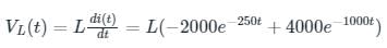
At t = 0 its value is given as
VL = 0.5 × 10⁻³ × (- 2000 + 4000)
VL = 1 V
_______ is defined as a measure of how easily a circuit or device will allow current to flow through it.- a)Resistance
- b)Admittance
- c)Capacitance
- d)Impedance
Correct answer is option 'B'. Can you explain this answer?
_______ is defined as a measure of how easily a circuit or device will allow current to flow through it.
a)
Resistance
b)
Admittance
c)
Capacitance
d)
Impedance
 | Cstoppers Instructors answered |
Resistance
It is an electrical parameter that is used as the measurement of opposition to the electric current.
The reciprocal of the resistance is called the 'Admittance'.
Resistance is defined as:
R = ρl / A
ρ: Resistivity of the material
l: length of the conductor
A: Area of the cross-section of the conductor.
It is measured in Ω.
Impedance:
The complex quantity of the resistance is defined as the Impedance of a circuit.
It is the same as that of the resistance.
Admittance
It is defined as the parameter which is used to measure the flow of current easily in a circuit.
admitatance = 1 / resistance
It is measured in Ω-1 or Siemens(S).
From Ohm's law admittance is:
Admittance = I / V
Capacitance
It is an electrical element that stores energy in the form of a static electric charge.
Energy stored in a capacitor is:
E = 1 / 2CV2
V: Voltage across the capacitor.
SI unit is Farads. (F)
Conclusion:
Option 2 is correct.
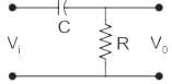
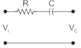
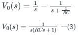
If the step response to the input step amplitude of 1 V is given by Vo(t) = (1 - e-t / RC), the network can be represented by:- a)

- b)
- c)
- d)
Correct answer is option 'A'. Can you explain this answer?
If the step response to the input step amplitude of 1 V is given by Vo(t) = (1 - e-t / RC), the network can be represented by:
a)
b)
c)
d)
| | Naroj Boda answered |
Concept:
A transfer function is defined as the ratio of the Laplace transform of output to the Laplace transform of input when initial conditions are zero.

Where, Vo = Output voltage
Vi = input voltage
Calculation:
Vo(t) = (1 - e-t / RC) ---(1)
Vi(t) = 1 V ---(2)
Applying Laplace transform to the (1) equation:
Now taking Laplace transform of equation (2):
Vi(s) = 1 / s
Now dividing V0(s) by Vi(s) we get:

Now consider the diagram given in option(a):
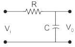
Finding V0 by using voltage division rule:
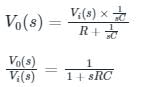
Hence it gives the same transfer function as calculated in equation (4)
Hence option (a) is the correct answer.
What will be the period of the sinusoid, v(t) = 12 cos (50t + 30°)?- a)0.1257 s
- b)1.257 s
- c)12.57 s
- d)50 s
Correct answer is option 'A'. Can you explain this answer?
What will be the period of the sinusoid, v(t) = 12 cos (50t + 30°)?
a)
0.1257 s
b)
1.257 s
c)
12.57 s
d)
50 s
| | Disha Das answered |
To determine the period of the sinusoid, we need to find the value of the coefficient of 't' in the argument of the cosine function.
In this case, the coefficient of 't' is 50. The period of a sinusoid is given by 2π divided by the coefficient of 't'. Therefore, the period is:
Period = 2π / 50
Simplifying this expression, we get:
Period = π / 25
In this case, the coefficient of 't' is 50. The period of a sinusoid is given by 2π divided by the coefficient of 't'. Therefore, the period is:
Period = 2π / 50
Simplifying this expression, we get:
Period = π / 25
Phasor diagram below is best describing the __________- a)Open circuit characteristic of alternator
- b)Short circuit characteristic of alternator
- c)External circuit characteristic of alternator
- d)Internal circuit characteristic of alternator
Correct answer is option 'A'. Can you explain this answer?
Phasor diagram below is best describing the __________
a)
Open circuit characteristic of alternator
b)
Short circuit characteristic of alternator
c)
External circuit characteristic of alternator
d)
Internal circuit characteristic of alternator
| | Shivani Saha answered |
**Phasor Diagram for Open Circuit Characteristic of Alternator**
The correct answer is option 'A', which states that the phasor diagram best describes the open circuit characteristic of an alternator. Let's understand why this is the correct answer.
**Explanation:**
An alternator is a device that converts mechanical energy into electrical energy. It consists of a rotor (rotating part) and a stator (stationary part). When the rotor is rotated, it induces electromotive force (EMF) in the stator windings, which generates electrical power.
The open circuit characteristic of an alternator refers to the relationship between the terminal voltage of the alternator and its field current when there is no load connected to the alternator. In other words, it represents the behavior of the alternator when there is no external electrical load connected.
**Phasor Diagram:**
A phasor diagram is a graphical representation of the amplitude and phase relationship between different quantities in an AC circuit. It is a vector diagram that helps visualize the relationship between voltage and current in an AC circuit.
In the case of the open circuit characteristic of an alternator, the phasor diagram represents the relationship between the terminal voltage (Vt) and the field current (If) of the alternator.
**Interpretation of Phasor Diagram:**
The phasor diagram for the open circuit characteristic of an alternator will have the following features:
1. The phasor representing the terminal voltage (Vt) will be the reference phasor and will be oriented along the horizontal axis (real axis).
2. The phasor representing the field current (If) will be oriented at an angle with respect to the reference phasor. The angle represents the phase difference between the terminal voltage and the field current.
3. The length of the field current phasor represents the magnitude of the field current.
4. The phasor diagram may also include the phasor representing the armature reaction, which is the magnetic field produced by the armature windings of the alternator. This phasor will be oriented at a different angle with respect to the reference phasor.
**Conclusion:**
Based on the above explanation, it is clear that the phasor diagram best describes the open circuit characteristic of an alternator. The phasor diagram represents the relationship between the terminal voltage and the field current of the alternator in an open circuit condition.
Calculate the value of V1 and V2.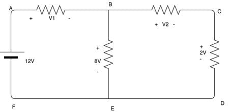
- a)4V, 6V
- b)5V, 6V
- c)6V, 7V
- d)7V, 8V
Correct answer is option 'A'. Can you explain this answer?
Calculate the value of V1 and V2.
a)
4V, 6V
b)
5V, 6V
c)
6V, 7V
d)
7V, 8V
| | Cstoppers Instructors answered |
Using KVL,
12 - V1 - 8 = 0.
V1 = 4V.
8 - V2 - 2=0.
V2 = 6V.
12 - V1 - 8 = 0.
V1 = 4V.
8 - V2 - 2=0.
V2 = 6V.
An AC voltage is given by v(t) = 5 + sin(2000πt), what is the time period and the dc component in v(t)?- a)0.05 ms, 0V
- b)1 ms, 0V
- c)0.05 ms, 5V
- d)1 ms, 5V
Correct answer is option 'D'. Can you explain this answer?
An AC voltage is given by v(t) = 5 + sin(2000πt), what is the time period and the dc component in v(t)?
a)
0.05 ms, 0V
b)
1 ms, 0V
c)
0.05 ms, 5V
d)
1 ms, 5V
| | Pooja Patel answered |
Concept
For a DC signal
- The average value over one time period is non zero
- The non-zero value is known as the DC value
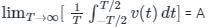
- 'A 'is the DC component of the signal
Calculation
Given the signal v(t) = 5 + sin(2000πt)
Now 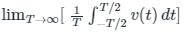
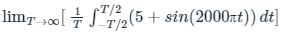
we have, 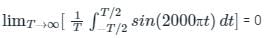
The average value of sinusoidal signal over one time period is always 0
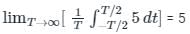
Hence the DC component of the signal v(t) is 5
Now observe the AC component in signal v(t)
sin(2000πt) is the AC component
The angular frequency ω = 2000π
Also ω = 2π / T ; here T is the Time period of the signal
2π / T= 2000π
T = 10-3 s
T =1 ms
The Time period of the signal is 1 ms
Therefore the correct answer is option 4
If the voltage and current in an A.C. circuit is 90° out of phase, then the power in the circuit will be -- a)Minimum
- b)Maximum
- c)Zero
- d)90 Watt
Correct answer is option 'C'. Can you explain this answer?
If the voltage and current in an A.C. circuit is 90° out of phase, then the power in the circuit will be -
a)
Minimum
b)
Maximum
c)
Zero
d)
90 Watt
| | Puja Shah answered |
Understanding A.C. Circuits
In an alternating current (A.C.) circuit, the relationship between voltage and current is crucial for determining the power consumed. When voltage and current are 90° out of phase, it has significant implications for power calculation.
Power in A.C. Circuits
- Power in A.C. circuits is calculated using the formula:
- P = V * I * cos(φ)
- Where:
- P = Power (Watts)
- V = Voltage (Volts)
- I = Current (Amperes)
- φ = Phase angle (degrees) between voltage and current
Phase Angle Effect
- When the phase angle φ is 90°:
- cos(90°) = 0
- Thus, P = V * I * 0 = 0
Conclusion: Zero Power
- Hence, when voltage and current are 90° out of phase, the power consumed in the circuit is zero.
- This indicates that no real work is done, and all the energy is oscillating back and forth without being utilized.
Implications in Circuit Design
- Circuits designed with this phase difference can be inefficient as they do not contribute to useful power.
- Understanding these phase relationships is crucial for electrical engineers to optimize circuit performance.
In summary, when voltage and current are 90° out of phase in an A.C. circuit, the result is zero power, meaning energy is not effectively converted into useful work.
For a pure resistance supplied through a sinusoidal voltage, the phase difference between the voltage and current phasors will be _______.- a)0°
- b)45°
- c)180°
- d)90°
Correct answer is option 'A'. Can you explain this answer?
For a pure resistance supplied through a sinusoidal voltage, the phase difference between the voltage and current phasors will be _______.
a)
0°
b)
45°
c)
180°
d)
90°
| | Pooja Patel answered |
Resistance:
- If the pure resistive element is present in the circuit, then the current is in phase with the voltage. So angle is 0°
- The power factor in this case is unity.
Inductance:
- If the pure inductive element is present in the circuit, then the current lags the voltage by 90 degrees.
- The power factor in this case is lagging.
Capacitance:
- If the pure capacitive element is present in the circuit, then the current leads the voltage by 90 degrees.
- The power factor, in this case, is leading.
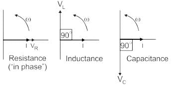
Hence the correct option for angle between the current and voltage in pure resistive circuit is zero or 0°.
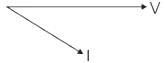
The phasor diagram of a load is as follows: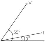
- a)RC load
- b)Pure inductor
- c)RL load or RLC with the inductive reactance more than the capacitive reactance
- d)Pure capacitor
Correct answer is option 'C'. Can you explain this answer?
The phasor diagram of a load is as follows:
a)
RC load
b)
Pure inductor
c)
RL load or RLC with the inductive reactance more than the capacitive reactance
d)
Pure capacitor
| | Pooja Patel answered |
Types of loads and Phasor Diagrams:
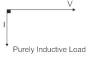
Pure Inductor load:
- The load which contains only inductance (L) and not any other quantities like resistance and capacitance in the circuit is called a Pure inductive load.
- In this type of load, the current lags behind the voltage by an angle of 90 degrees.
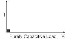
Pure capacitor:
- The load which contains only capacitance (C) and not any other quantities like resistance and inductance in the circuit is called a Pure capacitive load.
- In this type of load, the current leads the voltage by an angle of 90 degrees.
RL load:
- The load which contains only Resistance (R) and Inductance (L) and not any other quantities like capacitance in the circuit is called a RL load.
- In this type of load, the current lags behind the voltage by an angle between 0 to 90 degrees.
RLC Load:
- When a pure resistance of R ohms, a pure inductance of L Henry, and a pure capacitance of C farads are connected together in series combination with each other then RLC Seriesload is formed.
- As all the three elements are connected in series so, the current flowing through each element of the load will be the same as the total current I flowing in the load.
Case I
RLC load with inductive reactance more than the capacitive reactance
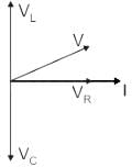
Where
VL = Inductor voltage
VC = Capacitor voltage
I = Current
V = Supply voltage
VR = Resistor Voltage
Case II
RLC load with inductive reactance lesser than the capacitive reactance
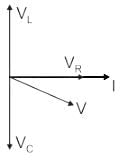
So If we observe the phasor diagram between V and I in all cases, RL load or RLC with inductive reactance more than the capacitive reactance (Case II) matches the given phasor.
Find the ROC of x(t) = e-2t u(t) + e-3t u(t).- a)σ > 2
- b)σ > 3
- c)σ > -3
- d)σ > -2
Correct answer is option 'D'. Can you explain this answer?
Find the ROC of x(t) = e-2t u(t) + e-3t u(t).
a)
σ > 2
b)
σ > 3
c)
σ > -3
d)
σ > -2
| | Nikhil Iyer answered |
To find the region of convergence (ROC) of the given function x(t) = e^(-2t) u(t) * e^(-3t) u(t), we need to determine the range of values for which the Laplace transform of x(t) converges.
The Laplace transform of x(t) is given by X(s) = ∫[0,∞] e^(-2t) u(t) * e^(-3t) u(t) * e^(-st) dt.
Since both terms e^(-2t) and e^(-3t) are multiplied together, we can combine them into a single term: e^(-5t).
X(s) = ∫[0,∞] e^(-5t) u(t) * e^(-st) dt.
Applying the properties of the unit step function, we can rewrite the integral as:
X(s) = ∫[0,∞] e^(-5t) e^(-st) dt.
Using the properties of exponentials, we can simplify the expression:
X(s) = ∫[0,∞] e^(-(5+s)t) dt.
Integrating this expression, we get:
X(s) = [-1/(5+s)] * e^(-(5+s)t) | from 0 to ∞.
Evaluating the limits, we have:
X(s) = [-1/(5+s)] * (e^(-(5+s)*∞) - e^(-(5+s)*0)).
As t approaches infinity, e^(-(5+s)*∞) goes to zero, and e^(-(5+s)*0) equals 1.
Thus, we have:
X(s) = [-1/(5+s)] * (0 - 1) = 1/(s+5).
The Laplace transform X(s) = 1/(s+5) converges for all values of s except for s = -5. Therefore, the ROC of x(t) is given by Re(s) > -5.
Find the equivalent thevenin’s resistance between terminals A and B in the circuit shown below.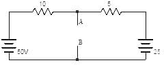
- a)333
- b)33.3
- c)3.33
- d)0.333
Correct answer is option 'C'. Can you explain this answer?
Find the equivalent thevenin’s resistance between terminals A and B in the circuit shown below.
a)
333
b)
33.3
c)
3.33
d)
0.333
| | Pooja Patel answered |
To find Rth, two voltage sources are removed and replaced with short circuit. The resistance at terminals AB then is the parallel combination of the 10Ω resistor and 5Ω resistor
⇒ Rth=(10 × 5)/15 = 3.33Ω.
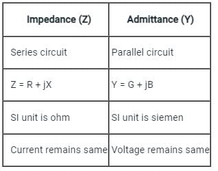
The relationship between impedance (Z) and admittance (Y) is- a)Z = 1/Y
- b)Z = 1 + Y
- c)Z = 1 - Y
- d)Z = Y2
Correct answer is option 'A'. Can you explain this answer?
The relationship between impedance (Z) and admittance (Y) is
a)
Z = 1/Y
b)
Z = 1 + Y
c)
Z = 1 - Y
d)
Z = Y2
| | Pooja Patel answered |
The relationship between the impedance and admittance is given by:
Z = 1/Y
where Z = Impedance
Y = Admittance
The impedance is analogous to admittance in the following ways:
Which, among the following is the correct expression for admittance?- a)Y = Z
- b)Y = 1/Z
- c)Y = Z2
- d)Y = 1/Z2
Correct answer is option 'B'. Can you explain this answer?
Which, among the following is the correct expression for admittance?
a)
Y = Z
b)
Y = 1/Z
c)
Y = Z2
d)
Y = 1/Z2
| | Pooja Patel answered |
We know that admittance is the reciprocal of impedance, hence the correct expression for admittance is:
Y = 1/Z.
Y = 1/Z.
Transfer function may be defined as ______- a)Ratio of out to input
- b)Ratio of laplace transform of output to input
- c)Ratio of laplace transform of output to input with zero initial conditions
- d)None of the mentioned
Correct answer is option 'C'. Can you explain this answer?
Transfer function may be defined as ______
a)
Ratio of out to input
b)
Ratio of laplace transform of output to input
c)
Ratio of laplace transform of output to input with zero initial conditions
d)
None of the mentioned
| | Pooja Patel answered |
Transfer function may be defined as the ratio of laplace transform of output to input with zero initial conditions.
Which of the following equation correctly represents the exact phasor diagram of transformer?- a)V1 = E1 + I1R1 + jI1X1
- b)V1 = E1 + I1R1 + jI2X2
- c)V2 = E2 + I1R1 + jI1X1
- d)V1 = E1 - I1R1 + jI1X1
Correct answer is option 'A'. Can you explain this answer?
Which of the following equation correctly represents the exact phasor diagram of transformer?
a)
V1 = E1 + I1R1 + jI1X1
b)
V1 = E1 + I1R1 + jI2X2
c)
V2 = E2 + I1R1 + jI1X1
d)
V1 = E1 - I1R1 + jI1X1
| | Pooja Patel answered |
According to the primary and secondary equivalent circuits of a transformer equation stated in option 1 correctly suits with the kirchoff’s voltage law for primary side of a transformer, similarly equation for secondary side can also be written down.
A sinusoid wave is expressed as 5 sin(4πt – 60°). Find the frequency.- a)2 Hz
- b)50 Hz
- c)60 Hz
- d)20 Hz
Correct answer is option 'A'. Can you explain this answer?
A sinusoid wave is expressed as 5 sin(4πt – 60°). Find the frequency.
a)
2 Hz
b)
50 Hz
c)
60 Hz
d)
20 Hz
| | Pooja Patel answered |
Concept:
Considered a sinusoidal Alternating wave of voltage and current
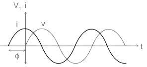
From the waveform:
v = Vmsin(ωt)
And,
i = Imsin(ωt + ϕ)
Where Vm and Im are the maximum value of instantaneous voltage and current respectively.
v, i is the instantaneous value of voltage and current at any instant t.
ω is the angular frequency in radian/second.
And, ω = 2πf
f is the frequency in Hz
From the above three equations instantaneous value of voltage and current can be written as:
v = Vmsin(2πft)
And,
i = Imsin(2πft + ϕ)
Calculation:
Sinusoidal expression of the wave is given as 5 sin (4πt – 60°)
Comparing the above expression with the given equation:
as:
v = Vmsin(2πft)
Or,
i = Imsin(2πft + ϕ)
Hence, ω = 4π
We know that,
ω = 2πf
∴ 4π = 2πf
∴ f = 2 Hz
if the impedance of a system is 4 ohm, calculate its admittance.- a)0.25 ohm-1
- b)4 ohm-1
- c)25 ohm-1
- d)0.4 ohm-1
Correct answer is option 'A'. Can you explain this answer?
if the impedance of a system is 4 ohm, calculate its admittance.
a)
0.25 ohm-1
b)
4 ohm-1
c)
25 ohm-1
d)
0.4 ohm-1
| | Alok Khanna answered |
To calculate the admittance of a system, we need to use the formula:
Admittance (Y) = 1 / Impedance (Z)
Given that the impedance of the system is 4 ohm, we can calculate the admittance as follows:
Admittance (Y) = 1 / 4 ohm
Admittance (Y) = 0.25 ohm^(-1)
Therefore, the correct answer is option 'A' - 0.25 ohm^(-1).
Explanation:
Impedance is a complex quantity that represents the combined effect of resistance and reactance in an electrical circuit. It is expressed in ohms and is denoted by the symbol 'Z'. Impedance consists of two components: resistance (R) and reactance (X), which can be either inductive or capacitive.
Admittance, on the other hand, is the reciprocal of impedance and represents the ease with which an electrical circuit allows the flow of current. It is also expressed in ohms but with a negative exponent, indicating its inverse relationship to impedance. Admittance is denoted by the symbol 'Y'.
To calculate the admittance of a system, we simply take the reciprocal of its impedance. In this case, the impedance is given as 4 ohms, so we divide 1 by 4 to get the admittance.
Admittance (Y) = 1 / 4 ohm
Admittance (Y) = 0.25 ohm^(-1)
Therefore, the correct answer is option 'A' - 0.25 ohm^(-1). This means that the system allows the flow of 0.25 amperes of current per volt of applied voltage.
Any system is said to be stable if and only if ____________- a)It poles lies at the left of imaginary axis
- b)It zeros lies at the left of imaginary axis
- c)It poles lies at the right of imaginary axis
- d)It zeros lies at the right of imaginary axis
Correct answer is option 'A'. Can you explain this answer?
Any system is said to be stable if and only if ____________
a)
It poles lies at the left of imaginary axis
b)
It zeros lies at the left of imaginary axis
c)
It poles lies at the right of imaginary axis
d)
It zeros lies at the right of imaginary axis
| | Pooja Patel answered |
Any system is said to be stable if and only if it poles lies at the left of imaginary axis.
At θ = π/2, positive portion is __________ negative portion in power cycle.- a)greater than
- b)less than
- c)equal to
- d)greater than or equal to
Correct answer is option 'C'. Can you explain this answer?
At θ = π/2, positive portion is __________ negative portion in power cycle.
a)
greater than
b)
less than
c)
equal to
d)
greater than or equal to
 | EduRev GATE answered |
At θ = π/2, the area under positive portion is equal to the area under negative portion in power cycle. At this instant the power dissipated in the circuit is zero.
What will be the transfer function of the system shown below?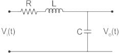
- a)

- b)RCs2 + LCs + 1
- c)

- d)LCs2 + RCs + 1
Correct answer is option 'A'. Can you explain this answer?
What will be the transfer function of the system shown below?
a)
b)
RCs2 + LCs + 1
c)
d)
LCs2 + RCs + 1
| | Pooja Patel answered |
Concept:
Transfer function:
The transfer function is defined as the ratio of the Laplace transform of the output variable to the input variable with all initial conditions zero.
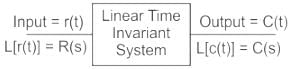
TF = L[output] / L[input]| Initial conditions = 0
TF = C(s) / R(s)
The transfer function of a linear time-invariant system can also be defined as the Laplace transform of the impulse response, with all the initial conditions set to zero.
Application:
The given circuit can be drawn as in Laplace domain as shown,
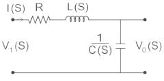
For the circuit above,
Transfer Function = 
We have,
Vi (S) = I(S) (R + LS + 1/Cs)
And, Vo (S) = I(S) (1Cs)
From equation (1),
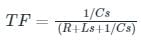
⇒ Transfer Function = 
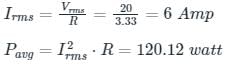
The average power consumed by the following circuit is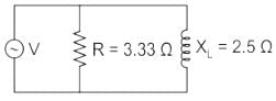 Vrms = 20∠ 53.13°V
 - a)100 W
- b)110 W
- c)120 W
- d)160 W
Correct answer is option 'C'. Can you explain this answer?
The average power consumed by the following circuit is
Vrms = 20∠ 53.13°V
a)
100 W
b)
110 W
c)
120 W
d)
160 W
| | Zoya Sharma answered |
Concept:
- “Average power observed by Resistor” (P)
- “Reactive power observed by Inductor OR capacitor” (Q).
Calculation:
Since we know active power OR average power observed by Inductor is zero.
Method 1:
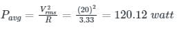
Method 2:
Current through Resistor :
The equation of instantaneous power is?- a)P (t) = (VmIm/2)(cos(2ωt + θ) + sinθ)
- b)P (t) = (VmIm/2)(sin(2ωt + θ) + cosθ)
- c)P (t) = (VmIm/2)(cos(2ωt + θ) + cosθ)
- d)P (t) = (VmIm/2)(sin(2ωt + θ) + sinθ)
Correct answer is option 'C'. Can you explain this answer?
The equation of instantaneous power is?
a)
P (t) = (VmIm/2)(cos(2ωt + θ) + sinθ)
b)
P (t) = (VmIm/2)(sin(2ωt + θ) + cosθ)
c)
P (t) = (VmIm/2)(cos(2ωt + θ) + cosθ)
d)
P (t) = (VmIm/2)(sin(2ωt + θ) + sinθ)
| | EduRev GATE answered |
The equation of instantaneous power is P (t) = (VmIm/2)(cos(2ωt + θ) + cosθ). It consists of two parts. One is a fixed part and the other is time varying which has frequency twice that of the voltage or current wave forms.
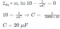
In the circuit shown, the current I flowing through the 50 Ω resistor will be zero if the value of capacitor C (in μF) is ______.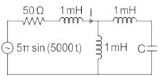
Correct answer is '20'. Can you explain this answer?
In the circuit shown, the current I flowing through the 50 Ω resistor will be zero if the value of capacitor C (in μF) is ______.
| | Cstoppers Instructors answered |
Concept:
Current through an open circuit or through a circuit with impedance tending to infinity is zero.
Calculation:
We are given a circuit shown below:

The impedance seen from the voltage source is Zeq (say) which can be calculated as:
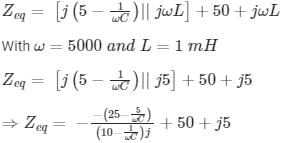
For I = 0, Zeq → ∞ --- (1)
The time varying part in the equation of instantaneous power has frequency ________________ that of the frequency of voltage or current wave forms.- a)equal to
- b)twice
- c)thrice
- d)four times
Correct answer is option 'B'. Can you explain this answer?
The time varying part in the equation of instantaneous power has frequency ________________ that of the frequency of voltage or current wave forms.
a)
equal to
b)
twice
c)
thrice
d)
four times
| | Prasad Saini answered |
Understanding Instantaneous Power
Instantaneous power in an electrical circuit is defined as the product of the instantaneous voltage and current at any given moment. The equation for instantaneous power (p(t)) can be expressed as:
p(t) = v(t) * i(t)
Frequency of Voltage and Current
- The voltage and current waveforms in AC circuits usually have a frequency (f) that is characteristic of the system, typically 50 Hz or 60 Hz, depending on the region.
- These waveforms can be represented mathematically as sinusoidal functions, such as:
- v(t) = Vm * sin(ωt)
- i(t) = Im * sin(ωt)
- Here, ω represents the angular frequency, which is related to the frequency by ω = 2πf.
Deriving Instantaneous Power's Frequency
- When you multiply these two sinusoidal functions, you can expand the product using trigonometric identities:
- p(t) = Vm * Im * sin(ωt) * sin(ωt)
- This results in terms that include:
- A constant term (average power)
- A term that oscillates at the frequency of the original waveforms (ω)
- A term that oscillates at twice the frequency (2ω), which is the key point of interest.
Conclusion
- The time-varying part of the instantaneous power equation oscillates at twice the frequency of the voltage or current waveforms.
- Therefore, the correct answer is option 'B': twice the frequency.
Understanding this concept is crucial in electrical engineering, especially in analyzing AC circuits and their power characteristics.
Calculate the voltage across the 10 ohm resistor.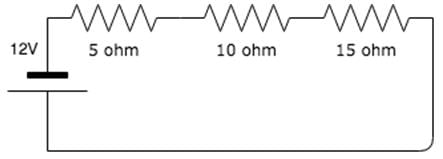
- a)12V
- b)4V
- c)10V
- d)0V
Correct answer is option 'B'. Can you explain this answer?
Calculate the voltage across the 10 ohm resistor.
a)
12V
b)
4V
c)
10V
d)
0V
| | Naroj Boda answered |
Total resistance = 5 + 10 + 15 = 30 ohm. Current in the circuit is 12/30 A.
Voltage across 10 ohm resistor is 10 x (12/30) = 4V.
Voltage across 10 ohm resistor is 10 x (12/30) = 4V.
In purely resistive circuit, energy delivered by source is ____________ by resistance.- a)dissipated in the form of heat
- b)stored as electric field
- c)stored as magnetic field
- d)returned to source
Correct answer is option 'A'. Can you explain this answer?
In purely resistive circuit, energy delivered by source is ____________ by resistance.
a)
dissipated in the form of heat
b)
stored as electric field
c)
stored as magnetic field
d)
returned to source
 | Bayshore Academy answered |
In purely resistive circuit, energy delivered by source is dissipated in the form of heat by resistance and is not stored as either electric field or magnetic field.
In the case of a sinusoidal current, the unit of the amplitude is:- a)Radians/second
- b)Hertz
- c)Radians
- d)Amperes
Correct answer is option 'D'. Can you explain this answer?
In the case of a sinusoidal current, the unit of the amplitude is:
a)
Radians/second
b)
Hertz
c)
Radians
d)
Amperes
| | Pooja Patel answered |
Waveform: The curve obtains by plotting the instantaneous value of any electrical quantity such as voltage, current, or power.
Cycle: One complete set of positive and negative values or maximum or minimum value of the alternating quantity is called a cycle.
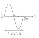
Note: One-half cycle of the wave is called Alternation.
Amplitude: the maximum value of the positive or negative alternative quantity is called Amplitude.
- For sinusoidal current, the unit of the amplitude is amperes.
- For sinusoidal voltage, the unit of the amplitude is volts.
- It is also known as peak value or crest value.
- Peak-Peak Value = 2 × Amplitude
- In the given figure amplitude of the waveform is Vm.

Time period (T): It is the time required to complete one cycle. It measured in seconds.
Frequency: The number of cycles completed per second is called frequency.
f = 1 / T
It measured in Hz or radian/sec.
Three 400 Ω resistors are connected in delta and powered by a 400 V (rms), 50 Hz balanced, symmetrical R - Y - B sequence, three-phase three-wire mains. The rms value of the line current (in amperes, rounded off to one decimal place) is
Correct answer is between '1.7,1.8'. Can you explain this answer?
Three 400 Ω resistors are connected in delta and powered by a 400 V (rms), 50 Hz balanced, symmetrical R - Y - B sequence, three-phase three-wire mains. The rms value of the line current (in amperes, rounded off to one decimal place) is
| | Pooja Patel answered |

In delta connection, VL = Vph = 400 Ω
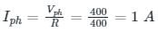
ILine = √3 Iphase = √3 × 1 = 1.732 A
The rms value is _________ times he maximum value- a)1.414
- b)0.5
- c)2
- d)0.707
Correct answer is option 'D'. Can you explain this answer?
The rms value is _________ times he maximum value
a)
1.414
b)
0.5
c)
2
d)
0.707
| | Pooja Patel answered |
We know that the rms value is 1/√2 times the maximum value, hence the rms value is 0.707 times the maximum value.
If two currents are in the same direction at any instant of time in a given branch of a circuit, the net current at that instant.
- a)Is zero
- b)Is the sum of the two currents
- c)Is the difference between the two currents
- d)Cannot be determined
Correct answer is option 'B'. Can you explain this answer?
If two currents are in the same direction at any instant of time in a given branch of a circuit, the net current at that instant.
a)
Is zero
b)
Is the sum of the two currents
c)
Is the difference between the two currents
d)
Cannot be determined
| | Sahil Datta answered |
Net Current in a Circuit with Two Currents in the Same Direction
Introduction:
When analyzing circuits, it is important to understand the behavior of currents flowing through different branches. In some cases, multiple currents may flow in the same direction within a specific branch. This scenario raises the question of how these currents interact with each other and what the resulting net current is.
Explanation:
When two currents flow in the same direction at any given instant of time in a specific branch of a circuit, the net current at that instant is equal to the sum of the two currents.
Reasoning:
To understand why the net current is the sum of the two currents, let's consider the basic principles of current flow.
1. Kirchhoff's Current Law (KCL):
According to KCL, the sum of currents entering and leaving a node in a circuit must be equal to zero. In other words, the total current flowing into a node is equal to the total current flowing out of it.
2. Current Conservation:
In a closed circuit, current is conserved. It means that the total current entering a junction is equal to the total current leaving that junction.
Analysis:
Now, let's consider a branch in a circuit where two currents (I1 and I2) are flowing in the same direction at a particular instant of time.
1. Current I1:
- Enters the branch from one end.
- Flows through the branch.
- Leaves the branch from the other end.
2. Current I2:
- Enters the branch from one end.
- Flows through the branch.
- Leaves the branch from the other end.
Since both currents enter and leave the branch, the net current at that instant must consider the sum of the two currents.
Conclusion:
Therefore, when two currents flow in the same direction at any instant of time in a given branch of a circuit, the net current at that instant is the sum of the two currents. This can be explained using Kirchhoff's Current Law and the principle of current conservation.
The current in the inductive circuit is 10 A and power factor is 0.866. The phasor representation of current is:- a)10 ∠-30°
- b)10 ∠ 30°
- c)10 ∠ 0.866
- d)5 ∠ -30°
Correct answer is option 'A'. Can you explain this answer?
The current in the inductive circuit is 10 A and power factor is 0.866. The phasor representation of current is:
a)
10 ∠-30°
b)
10 ∠ 30°
c)
10 ∠ 0.866
d)
5 ∠ -30°
| | Mansi Datta answered |
The phasor representation of current in an inductive circuit is given by:
I = I0 ∠θ
where I is the phasor representation of current, I0 is the magnitude of current, and θ is the phase angle.
Given that the current in the inductive circuit is 10 A and the power factor is 0.866, we can find the phase angle using the formula:
cos(θ) = power factor
cos(θ) = 0.866
θ = arccos(0.866) ≈ 30.96°
Therefore, the phasor representation of current is:
I = 10 ∠30.96°
A voltage v (t) = 100sinωt is applied to a circuit. The current flowing through the circuit is i(t) = 15sin(ωt-30⁰). Determine the average power delivered to the circuit.- a)620
- b)630
- c)640
- d)650
Correct answer is option 'D'. Can you explain this answer?
A voltage v (t) = 100sinωt is applied to a circuit. The current flowing through the circuit is i(t) = 15sin(ωt-30⁰). Determine the average power delivered to the circuit.
a)
620
b)
630
c)
640
d)
650
| | Mainak Pillai answered |
Calculation of Power
- The average power delivered to the circuit can be calculated using the formula: P_avg = (1/2)Vpk * Ipk * cos(θ)
- Where Vpk is the peak voltage (100V), Ipk is the peak current (15A), and θ is the phase angle between the voltage and current.
Calculating θ
- The phase angle between the voltage and current can be found by subtracting the phase angle of the current from the phase angle of the voltage.
- θ = 0° - (-30°) = 30°
Calculating Power
- P_avg = (1/2)(100)(15)cos(30°) = 650W
Therefore, the average power delivered to the circuit is 650W. Hence, the correct answer is option 'D'.
Find the voltage across 2Ω resistor due to 20V source in the circuit shown below: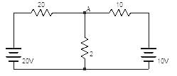
- a)1
- b)1.5
- c)2
- d)2.5
Correct answer is option 'B'. Can you explain this answer?
Find the voltage across 2Ω resistor due to 20V source in the circuit shown below:
a)
1
b)
1.5
c)
2
d)
2.5
| | Cstoppers Instructors answered |
The voltage at node A in the figure is
(V - 20)/20 + (V - 10)/10 + V/2 = 0
⇒ V = 3.07V. Now short circuiting 10V source,

(V - 20)/20 + V/2 + V/10 = 0
⇒ V = 1.5V.
(V - 20)/20 + (V - 10)/10 + V/2 = 0
⇒ V = 3.07V. Now short circuiting 10V source,
(V - 20)/20 + V/2 + V/10 = 0
⇒ V = 1.5V.
The transfer function of a linear system is the- a)Ratio of the output Vo(t) and input Vi(t)
- b)Ratio of the derivatives of the output and input
- c)Ratio of the Laplace transform of the output and that of the input with all initial conditions zeros.
- d)None of these
Correct answer is option 'C'. Can you explain this answer?
The transfer function of a linear system is the
a)
Ratio of the output Vo(t) and input Vi(t)
b)
Ratio of the derivatives of the output and input
c)
Ratio of the Laplace transform of the output and that of the input with all initial conditions zeros.
d)
None of these
| | Hrishikesh Yadav answered |
Transfer function is a fundamental concept in linear systems theory. It is a mathematical representation of the relationship between the input and output of a linear time-invariant (LTI) system. The transfer function is commonly denoted as H(s), where s is the complex variable representing the Laplace transform domain.
Ratio of Laplace Transforms
The correct option for the transfer function of a linear system is c) Ratio of the Laplace transform of the output and that of the input with all initial conditions zeros. This means that the transfer function H(s) is defined as the ratio of the Laplace transform of the output (Y(s)) to the Laplace transform of the input (X(s)).
H(s) = Y(s) / X(s)
This definition implies that the transfer function captures the complete dynamic behavior of the system by taking into account the initial conditions. It describes how the system responds to different input signals in the frequency domain.
Benefits of Transfer Function
The transfer function is a powerful tool for analyzing and designing linear systems. Here are a few key benefits of using transfer functions:
1. System Analysis: By manipulating the transfer function algebraically, we can derive important system properties such as poles, zeros, stability, and frequency response. These properties provide insights into the system's behavior and performance.
2. System Design: Transfer functions allow us to design controllers and filters to achieve desired system responses. By modifying the transfer function, we can shape the system's frequency response and improve its performance.
3. System Simulation: Transfer functions can be easily implemented in simulation tools to model and analyze the system's behavior. This enables engineers to test different scenarios and evaluate the system's performance before implementing it in real-world applications.
4. System Identification: Transfer functions can also be used in system identification, where the goal is to estimate the transfer function of an unknown system based on input-output data. This is crucial for understanding and modeling complex systems.
Conclusion
In summary, the transfer function of a linear system is defined as the ratio of the Laplace transform of the output to the Laplace transform of the input with all initial conditions zero. It provides a concise and powerful representation of the system's behavior in the frequency domain. By analyzing and manipulating the transfer function, engineers can gain valuable insights into the system's properties, design controllers, simulate system behavior, and identify unknown systems.
The non linear magnetization curve of a practical transformer will introduce _________- a)heating
- b)higher order harmonics
- c)magnetostriction
- d)all of the mentioned
Correct answer is option 'D'. Can you explain this answer?
The non linear magnetization curve of a practical transformer will introduce _________
a)
heating
b)
higher order harmonics
c)
magnetostriction
d)
all of the mentioned
| | Nandita Kulkarni answered |
Introduction
The non-linear magnetization curve of a practical transformer affects its performance in various ways. Understanding these effects helps in designing transformers that operate efficiently and reliably.
Heating
- Non-linear magnetization leads to increased losses in the core, primarily due to hysteresis and eddy currents.
- When the magnetic field is not linear, the transformer requires additional energy to magnetize and demagnetize the core, leading to heat generation.
- Excessive heating can result in insulation failure and reduced operational life.
Higher Order Harmonics
- The non-linear relationship between magnetizing force and magnetic flux density generates harmonics in the current waveform.
- These harmonics can distort the voltage and current waveforms, leading to inefficiencies.
- Higher order harmonics can cause additional heating and reduce the overall power factor of the transformer.
Magnetostriction
- Non-linear magnetization causes changes in the dimensions of the core material due to magnetostriction, which is the change in shape or size of a material when subjected to a magnetic field.
- This phenomenon can produce vibrations and noise, which may affect the transformer's mechanical integrity over time.
Conclusion
In summary, the non-linear magnetization curve of a practical transformer introduces several issues:
- Heating due to increased core losses
- Higher order harmonics that distort current and voltage
- Magnetostriction leading to vibrations and noise
Thus, all these factors (option 'D') must be considered in transformer design and operation to ensure efficiency and longevity.
Determine the average power delivered to the circuit consisting of an impedance Z = 5+j8 when the current flowing through the circuit is I = 5∠30⁰.- a)61.5
- b)62.5
- c)63.5
- d)64.5
Correct answer is option 'B'. Can you explain this answer?
Determine the average power delivered to the circuit consisting of an impedance Z = 5+j8 when the current flowing through the circuit is I = 5∠30⁰.
a)
61.5
b)
62.5
c)
63.5
d)
64.5
| | Debanshi Nair answered |
Understanding the Circuit Parameters
To determine the average power delivered to the circuit, we begin with the given parameters:
- Impedance (Z) = 5 + j8 ohms
- Current (I) = 5∠30° A
Convert Current to Rectangular Form
First, convert the current from polar to rectangular form:
- I = 5 * (cos(30°) + j*sin(30°))
- I = 5 * (0.866 + j*0.5)
- I = 4.33 + j2.5 A
Calculate Voltage (V)
Using Ohm's Law (V = I * Z):
- V = (4.33 + j2.5) * (5 + j8)
Calculating this product, we get:
- V = (4.33*5 - 2.5*8) + j(4.33*8 + 2.5*5)
- V = (21.65 - 20) + j(34.64 + 12.5)
- V = 1.65 + j47.14 V
Determine Average Power (P)
The average power (P) can be calculated using the formula:
- P = I_rms^2 * R
Where R is the real part of the impedance (5 ohms) and I_rms is the root mean square of the current.
Since I = 5A, I_rms = I / √2 = 5 / √2 = 3.54 A. Thus:
- P = (3.54^2) * 5
- P = 12.54 * 5 = 62.7 W
However, since we use the average power formula directly with the given current:
- P = 5^2 * (Real part of Z) / 2 = 25 * 5 / 2 = 62.5 W
Conclusion
The average power delivered to the circuit is approximately 62.5 W, which corresponds to option 'B'.
Chapter doubts & questions for A.C. Analysis - 3 Months Preparation for GATE Electrical 2026 is part of Electrical Engineering (EE) exam preparation. The chapters have been prepared according to the Electrical Engineering (EE) exam syllabus. The Chapter doubts & questions, notes, tests & MCQs are made for Electrical Engineering (EE) 2026 Exam. Find important definitions, questions, notes, meanings, examples, exercises, MCQs and online tests here.
Chapter doubts & questions of A.C. Analysis - 3 Months Preparation for GATE Electrical in English & Hindi are available as part of Electrical Engineering (EE) exam. Download more important topics, notes, lectures and mock test series for Electrical Engineering (EE) Exam by signing up for free.
3 Months Preparation for GATE Electrical676 videos|1399 docs|882 tests |