


All Exams > Electrical Engineering (EE) > 3 Months Preparation for GATE Electrical > All Questions
All questions of The Root Locus Technique for Electrical Engineering (EE) Exam
The characteristic equation of a closed loop control system is given by:
s2 + 2s +10 + K(s2 + 6s + 10) = 0
The angle of asymptotes for the root loci for K > 0 are given by- a)180°, 360°
- b)90°, 270°
- c)90°, 180°
- d)none of these
Correct answer is option 'D'. Can you explain this answer?
The characteristic equation of a closed loop control system is given by:
s2 + 2s +10 + K(s2 + 6s + 10) = 0
The angle of asymptotes for the root loci for K > 0 are given by
s2 + 2s +10 + K(s2 + 6s + 10) = 0
The angle of asymptotes for the root loci for K > 0 are given by
a)
180°, 360°
b)
90°, 270°
c)
90°, 180°
d)
none of these
| | Saumya Basak answered |
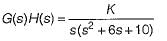
Given, s2 + 2s + 10 + K(s2 + 6s + 10) = 0
or,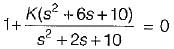
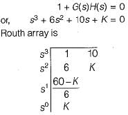
or, 1 + G(s)H(s) = 0
Thus, G(s)H(s) =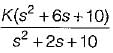
Here, number of open loop poles, P = 2. Number of open loop zero, Z = 2
∴ P - Z = 0.
Angle of asymptotes are given by:
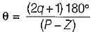
Sines P - Z= 0, therefore there are no angle of asymptotes for the root locus of the given system.
or,
or, 1 + G(s)H(s) = 0
Thus, G(s)H(s) =
Here, number of open loop poles, P = 2. Number of open loop zero, Z = 2
∴ P - Z = 0.
Angle of asymptotes are given by:
Sines P - Z= 0, therefore there are no angle of asymptotes for the root locus of the given system.

Assertion (A): From the root sensitivity standpoint, a system should not be operated at the breakaway points.
Reason (R): The root sensitivity at the breakaway points is zero.- a)Both A and R are true and R is a correct explanation of A.
- b)Both A and R are true but R is not a correct explanation of A.
- c)A is true but R is false.
- d)A is false but R is true.
Correct answer is option 'C'. Can you explain this answer?
Assertion (A): From the root sensitivity standpoint, a system should not be operated at the breakaway points.
Reason (R): The root sensitivity at the breakaway points is zero.
Reason (R): The root sensitivity at the breakaway points is zero.
a)
Both A and R are true and R is a correct explanation of A.
b)
Both A and R are true but R is not a correct explanation of A.
c)
A is true but R is false.
d)
A is false but R is true.
| | Sakshi Roy answered |
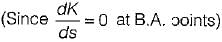
From the root sensitivity, standpoint, a system should not be operated at1the breakaway points because root sensitivity at breakaway point is infinite.
i.e.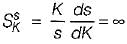
at breakaway points
Here, α = closed loop poles(s)
and β = system gain (K)
Thus,
or,
i.e.
at breakaway points
Here, α = closed loop poles(s)
and β = system gain (K)
Thus,
or,
Which of the following option is correct?
The root locus is the path of the roots of the characteristic equation traced out in the s-plane- a)as the output of the system is changed
- b)as the sensitivity is changed.
- c)as the system parameter is changed
- d)as the input of the system is changed
Correct answer is option 'C'. Can you explain this answer?
Which of the following option is correct?
The root locus is the path of the roots of the characteristic equation traced out in the s-plane
The root locus is the path of the roots of the characteristic equation traced out in the s-plane
a)
as the output of the system is changed
b)
as the sensitivity is changed.
c)
as the system parameter is changed
d)
as the input of the system is changed
| | Kiran Datta answered |
The root locus is defined as location of closed loop poles when system gain k is varied from zero to infinity.
Which of the following is not true regarding the existence of breakaway point in root locus technique?- a)A breakaway point exists between two zeros if the region between them is a part of root locus.
- b)If we see the root locus between two poles on real axis, then there is a breakaway point between these two poles.
- c)A break away point exists to the left of a zero on real axis if the region to the left of it is a part of root locus.
- d)A breakaway point exists to the left of a pole if the region to the left of it on real axis is a part of root locus.
Correct answer is option 'C'. Can you explain this answer?
Which of the following is not true regarding the existence of breakaway point in root locus technique?
a)
A breakaway point exists between two zeros if the region between them is a part of root locus.
b)
If we see the root locus between two poles on real axis, then there is a breakaway point between these two poles.
c)
A break away point exists to the left of a zero on real axis if the region to the left of it is a part of root locus.
d)
A breakaway point exists to the left of a pole if the region to the left of it on real axis is a part of root locus.
 | Starcoders answered |
- Root Locus Concept: The root locus is a graphical representation that shows how the roots of a system change with variations in a system parameter, typically the gain.
- Breakaway Point: This is a point on the real axis between two poles of the system where root locus branches diverge or converge.
- Statement C Analysis: A breakaway point cannot exist to the left of a zero on the real axis, because that portion is not influenced by the zero for root locus. Therefore, statement C is incorrect.
Number of intersection of the asymptotes of the complete root loci is- a)three
- b)unknown
- c)two
- d)one
Correct answer is option 'D'. Can you explain this answer?
Number of intersection of the asymptotes of the complete root loci is
a)
three
b)
unknown
c)
two
d)
one
| | Pranavi Tiwari answered |
Centroid is the intersection point of asymptotes of the complete root loci which lie on the real axis.
Consider the loop transfer function K(s + 6) / (s + 3)(s +5 ) In the root locus diagram the centroid will be located at: - a)-2
- b)-4
- c)-1
- d)-3
Correct answer is option 'A'. Can you explain this answer?
Consider the loop transfer function K(s + 6) / (s + 3)(s +5 ) In the root locus diagram the centroid will be located at:
a)
-2
b)
-4
c)
-1
d)
-3
| | Saikat Chakraborty answered |
Explanation:
Centroid Calculation:
- The centroid of the root locus can be calculated using the formula: Σ(p) - Σ(z) / N, where Σ(p) is the sum of poles, Σ(z) is the sum of zeros, and N is the number of poles and zeros to the right of the centroid.
- In this case, the sum of poles (Σ(p)) is 3 + 5 = 8 and the sum of zeros (Σ(z)) is 6.
- There are no poles or zeros to the right of the centroid, so N = 0.
- Therefore, the centroid of the root locus is given by (8 - 6) / 0 = 2 / 0, which tends to infinity.
- Since the centroid tends to infinity, it implies that the centroid is located at -2 on the real axis.
Therefore, the centroid will be located at -2 in the root locus diagram for the given loop transfer function.
Assertion ( A ) : An addition of real pole at s = - p0 in the transfer function G(s)H(s) of a control system results in the increase of stability margin.
Reason ( R ) : An addition of real pole at s = - p0 in the transfer function G(s)H(s) will make the resultant root loci bend towards the right.- a)Both A and R are true and R is a correct explanation of A.
- b)Both A and R are true but R is not a correct explanation of A.
- c)A is true but R is false.
- d)A is false but R is true.
Correct answer is option 'D'. Can you explain this answer?
Assertion ( A ) : An addition of real pole at s = - p0 in the transfer function G(s)H(s) of a control system results in the increase of stability margin.
Reason ( R ) : An addition of real pole at s = - p0 in the transfer function G(s)H(s) will make the resultant root loci bend towards the right.
Reason ( R ) : An addition of real pole at s = - p0 in the transfer function G(s)H(s) will make the resultant root loci bend towards the right.
a)
Both A and R are true and R is a correct explanation of A.
b)
Both A and R are true but R is not a correct explanation of A.
c)
A is true but R is false.
d)
A is false but R is true.
| | Upasana Pillai answered |
Assertion (A): Stability Margin and Real Pole Addition
- The assertion states that adding a real pole at s = -p0 in the transfer function G(s)H(s) increases the stability margin.
- This assertion is false. Adding a real pole typically decreases the stability margin because it can lead to a slower response and may cause the system to become less stable.
Reason (R): Effect on Root Loci
- The reason given is that adding a real pole at s = -p0 causes the resultant root loci to bend towards the right.
- This statement is true. Adding a pole can indeed cause the root loci to shift. However, the bending of the root loci towards the right typically implies a decrease in stability, not an increase.
Conclusion: Evaluating A and R
- Since A is false and R is true, the correct option is D: A is false but R is true.
- This means that while the reason correctly describes the behavior of root loci, it does not justify the assertion about the stability margin.
Key Takeaways
- Adding a pole generally reduces stability margin.
- Root loci bending behavior helps understand system dynamics but does not support the assertion regarding stability improvement.
This evaluation highlights the importance of understanding system dynamics in control theory, especially when analyzing how modifications to the transfer function affect system behavior.
Consider the following statements:
1. All the rules and properties for the construction of root loci in the s-plane can be applied to the construction of root loci of discrete data system in the z-plane without any modification.
2. The breakaway points of the root loci must always be on the real axis.
3. There is only, one intersection of the asymptotes of the complex root loci.
4. Adding a pole to Q(s)/P(s) has the general effect of pushing the root loci to the left, whereas adding a zero pushes the loci to the right.
Which of the above statements is/are not correct related to root locus technique in control system?- a)2 and 4
- b)1,2, 3 and 4
- c)3 and 4
- d)2, 3 and 4
Correct answer is option 'A'. Can you explain this answer?
Consider the following statements:
1. All the rules and properties for the construction of root loci in the s-plane can be applied to the construction of root loci of discrete data system in the z-plane without any modification.
2. The breakaway points of the root loci must always be on the real axis.
3. There is only, one intersection of the asymptotes of the complex root loci.
4. Adding a pole to Q(s)/P(s) has the general effect of pushing the root loci to the left, whereas adding a zero pushes the loci to the right.
Which of the above statements is/are not correct related to root locus technique in control system?
a)
2 and 4
b)
1,2, 3 and 4
c)
3 and 4
d)
2, 3 and 4
| | Ankita Das answered |
There is possibility of complex B.A. point. Also when a pole is added to OLTF, root locus pushes to right and reverse happens when a zero is added.
Consider the following statements pertaining to root locus techniques:
1. Routh-Hurwitz criterion may be used to find the intersections of the root loci on the imaginary axis.
2. Breakaway points on the root loci of an equation corresponds to multiple-order roots of the equation.
3. The breakaway points on the root loci of 1 + KG(s) H(s) = 0 must satisfy
4. n root loci arrive or depart a breakaway point at 180/n degrees.
Which of these statements are correct?- a)1, 2 and 3
- b)2, 3 and 4.
- c)1, 2, 3 and 4
- d)1, 2 and 4
Correct answer is option 'C'. Can you explain this answer?
Consider the following statements pertaining to root locus techniques:
1. Routh-Hurwitz criterion may be used to find the intersections of the root loci on the imaginary axis.
2. Breakaway points on the root loci of an equation corresponds to multiple-order roots of the equation.
3. The breakaway points on the root loci of 1 + KG(s) H(s) = 0 must satisfy
4. n root loci arrive or depart a breakaway point at 180/n degrees.
Which of these statements are correct?
a)
1, 2 and 3
b)
2, 3 and 4.
c)
1, 2, 3 and 4
d)
1, 2 and 4
 | Imtiaz Ahmad answered |
Statement 1 is true. The Routh-Hurwitz criterion is used to detect when closed-loop characteristic polynomial roots lie on the imaginary axis by forming the Routh array; setting an entire row to zero (or examining sign changes) yields the frequencies and gain values at which imaginary-axis crossings occur.
Statement 2 is true. A breakaway or break-in point on the real axis corresponds to a point where two or more root-locus branches meet or separate. At that point the characteristic equation has a repeated (multiple-order) root, e.g., a double root for two branches meeting.
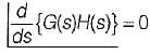
Statement 3 is true. Let L(s)=G(s)H(s). From 1+K L(s)=0 we get K = -1/L(s). A breakaway/break-in on the real axis occurs where dK/ds = 0 (extremum of K versus s). Differentiating gives:
K = -1/L(s)
dK/ds = 0 ⇒ (1/L(s)^2)·dL/ds = 0 ⇒ dL/ds = 0.
Thus the breakaway points satisfy d/ds [G(s)H(s)] = 0.
Statement 4 is false. For a root of multiplicity n the angles of arrival/departure are given by θ = (2q+1)π/n (i.e. θ = (2q+1)×180°/n) for q = 0,1,...,n-1. Adjacent branches are separated by 360°/n. The single value "180°/n" alone is not the general correct statement; it is incomplete and therefore the given statement is incorrect.
Conclusion: Statements 1, 2 and 3 are correct and statement 4 is incorrect; hence Option A is the correct choice.
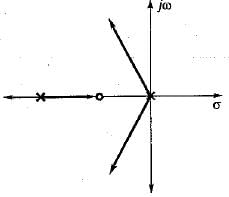
A unity feedback system has open-loop transfer function,
The valid root-loci for this system is- a)
- b)
- c)
- d)
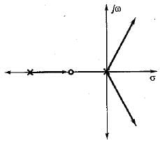
Correct answer is option 'A'. Can you explain this answer?
A unity feedback system has open-loop transfer function,
The valid root-loci for this system is
The valid root-loci for this system is
a)
b)
c)
d)
| | Vaishnavi Singh answered |
To find whether root locus intersects the imaginary axis or not, we construct Routh’s array. Characteristic equation is
s3 + βs2 + Ks + Kα = 0
Routh's array is:
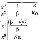
For β > α > 0, root-loci doesn't intersect the yico-axis and is stable for all positive values of K (no sign change in first column for β > α > 0 and K> 0).
Also, P= 3, Z = 1, P- Z = 2
Thus, two branches of RL will terminate at infinity while one branch will terminate at a zero. Therefore, possible root locus diagram will be represented by option (a).
s3 + βs2 + Ks + Kα = 0
Routh's array is:
For β > α > 0, root-loci doesn't intersect the yico-axis and is stable for all positive values of K (no sign change in first column for β > α > 0 and K> 0).
Also, P= 3, Z = 1, P- Z = 2
Thus, two branches of RL will terminate at infinity while one branch will terminate at a zero. Therefore, possible root locus diagram will be represented by option (a).
The open-loop transfer function of a unity feedback control system is given by:
The centroid and the angle of root locus asymptotes are respectively- a)
- b)zero and + 90°, -90
- c)zero and+120°,-120°
- d)
Correct answer is option 'B'. Can you explain this answer?
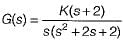
The open-loop transfer function of a unity feedback control system is given by:
The centroid and the angle of root locus asymptotes are respectively
The centroid and the angle of root locus asymptotes are respectively
a)
b)
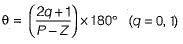
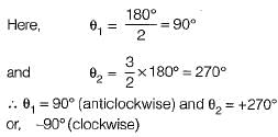
zero and + 90°, -90
c)
zero and+120°,-120°
d)
| | Sanjana Chakraborty answered |
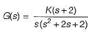
Number of open loop poies = P = 3
and number of open loop zeros = Z = 1
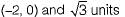
Poles are at: s = -1 ± j, 0 and zero is at s = -2
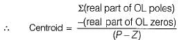
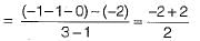
= 0
Here, P - Z = 2
So, angle of asymptotes are given by
The open loop transfer function of a system is given by
The number of loci terminating at infinity is- a)3
- b)2
- c)1
- d)0
Correct answer is option 'C'. Can you explain this answer?
The open loop transfer function of a system is given by
The number of loci terminating at infinity is
The number of loci terminating at infinity is
a)
3
b)
2
c)
1
d)
0
| | Isha Singh answered |
Here,
P = 2, Z = 3 and Z > P
∴ No. of branches of RL terminating at infinity
= Z - P = 3 - 2 - 1
P = 2, Z = 3 and Z > P
∴ No. of branches of RL terminating at infinity
= Z - P = 3 - 2 - 1
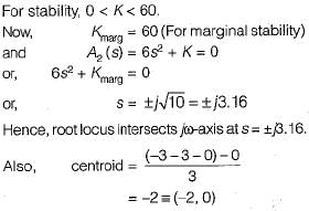
The open-loop transfer function of a closed loop control system is given as:
Which of the following statements is correct about the root locus of the above system?- a)Two number of branches of root locus will terminate at infinity. -
- b)For K = 40, the system is marginally stable.
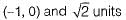
- c)The centroid of the given system is located at (-1,0).
- d)The root locus intersects the jω-axis at

Correct answer is option 'D'. Can you explain this answer?
The open-loop transfer function of a closed loop control system is given as:
Which of the following statements is correct about the root locus of the above system?
Which of the following statements is correct about the root locus of the above system?
a)
Two number of branches of root locus will terminate at infinity. -
b)
For K = 40, the system is marginally stable.
c)
The centroid of the given system is located at (-1,0).
d)
The root locus intersects the jω-axis at
| | Rishika Choudhury answered |
Number of branches terminating at infinity = 3 = P - Z.
Number of branches terminating at zero = Z= 0.
Poles are at s = 0 and s = -3 ± j1.

Since, three number of poles have to terminate at infinity, therefore the two complex poles will terminate at infinity due to which there will be intersection of root locus branches with jω-axis. Now, characteristic equation is
For the loop transfer function:

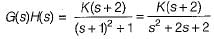
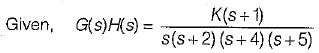
the angle of departure at s = j for K > 0 is- a)90°
- b)75°
- c)155°
- d)135°
Correct answer is option 'D'. Can you explain this answer?
For the loop transfer function:
the angle of departure at s = j for K > 0 is
the angle of departure at s = j for K > 0 is
a)
90°
b)
75°
c)
155°
d)
135°
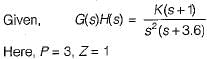
| | Mayank Sengupta answered |
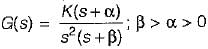
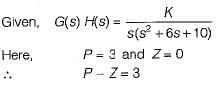
Given, G(s)H(s) = 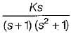
Here, P = 3, Z = 1, P - Z = 2
No. of branches of RL terminating at zero = 1.
No. of branches of RL termination at infinity = 2
Here, two branches of RL has to terminate at infinity.
Thus, the two imaginary poles will terminate at infinity.
Hence, we need to find angle of departure for which we join all poles and zeros with the imaainarv Dole at s = j1.
Now,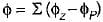
Here,
and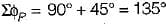
Thus, φ = (90° -135°) = - 45°
∴ Angle of departure is,
φD = 180° + φ
= 180° - 45° = 135°
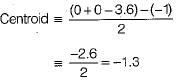
Considering the root locus diagram for a system with 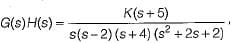 the meeting point of the asymptotes on the real axis occurs at
- a)-0.75
- b)-1.25
- c)-1.2
- d)-0.65
Correct answer is option 'A'. Can you explain this answer?
Considering the root locus diagram for a system with the meeting point of the asymptotes on the real axis occurs at
the meeting point of the asymptotes on the real axis occurs ata)
-0.75
b)
-1.25
c)
-1.2
d)
-0.65
 | Harpreet Singh answered |
Answer is +0.25 because one pole in RHS as given
s-2 so answer not in options
s-2 so answer not in options
Assertion (A): Root locus is a graphical method in which roots of the characteristic equation are plotted in s-plane for the different value of parameter.
Reason (R): The locus of the roots of the characteristic equation when gain is varied from zero to infinity is called root locus.- a)Both A and R are true and R is a correct explanation of A.
- b)Both A and R are true but R is not a correct explanation of A.
- c)A is true but R is false.
- d)A is false but R is true.
Correct answer is option 'A'. Can you explain this answer?
Assertion (A): Root locus is a graphical method in which roots of the characteristic equation are plotted in s-plane for the different value of parameter.
Reason (R): The locus of the roots of the characteristic equation when gain is varied from zero to infinity is called root locus.
Reason (R): The locus of the roots of the characteristic equation when gain is varied from zero to infinity is called root locus.
a)
Both A and R are true and R is a correct explanation of A.
b)
Both A and R are true but R is not a correct explanation of A.
c)
A is true but R is false.
d)
A is false but R is true.
| | Shivam Das answered |
Root Locus
Root locus is a graphical method used in control system analysis and design to determine the behavior of the roots of a characteristic equation as a parameter, typically the gain, is varied. It provides insights into the stability and transient response of a system.
Assertion (A): Root locus is a graphical method in which roots of the characteristic equation are plotted in s-plane for different values of the parameter.
Reason (R): The locus of the roots of the characteristic equation when gain is varied from zero to infinity is called root locus.
Explanation:
Root Locus Method
The root locus method is based on the principle of the characteristic equation. The characteristic equation is obtained by equating the denominator of the transfer function to zero. The roots of this equation determine the poles of the system.
The transfer function of a system is represented as:
G(s)H(s) = K(s + z1)(s + z2)...(s + zn) / (s + p1)(s + p2)...(s + pm)
Where G(s) is the open-loop transfer function, H(s) is the feedback transfer function, and K is the gain.
Plotting the Root Locus
To plot the root locus, the following steps are followed:
1. Determine the characteristic equation by equating the denominator of the transfer function to zero.
2. Identify the open-loop poles and zeros.
3. Draw the real axis and mark the poles and zeros on it.
4. Determine the angles of departure and arrival for each pole and zero.
5. Draw the root locus branches by following the rules:
- The root locus starts from the open-loop poles.
- The root locus moves towards the zeros.
- The root locus asymptotes and intersects the real axis at angles that sum up to 180 degrees.
- The root locus branches do not cross each other.
Explanation of Assertion (A)
The assertion states that the root locus is a graphical method in which the roots of the characteristic equation are plotted in the s-plane for different values of the parameter. This is true because the root locus provides a visual representation of the behavior of the roots as the parameter, typically the gain, is varied.
Explanation of Reason (R)
The reason states that the locus of the roots of the characteristic equation when the gain is varied from zero to infinity is called the root locus. This is true because the root locus represents the path traced by the roots of the characteristic equation as the gain is varied. It shows how the system's poles move in the s-plane as the gain changes.
Conclusion
Both Assertion (A) and Reason (R) are true, and Reason (R) is a correct explanation of Assertion (A). The root locus is indeed a graphical method in which the roots of the characteristic equation are plotted in the s-plane for different values of the parameter, and the locus of the roots when the gain is varied is known as the root locus.

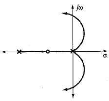
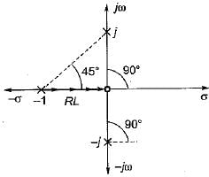
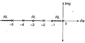
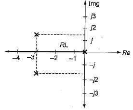
What is the open-loop transfer function of a unity feedback control system having root locus shown in the following figure?
- a)

- b)
- c)

- d)

Correct answer is option 'C'. Can you explain this answer?
What is the open-loop transfer function of a unity feedback control system having root locus shown in the following figure?
a)
b)
c)
d)
| | Anushka Sengupta answered |
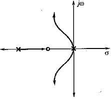
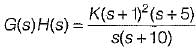
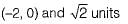
Branches of root locus either terminate at infinity or zero. Here, one branch is terminating at s = -2, therefore there is a zero at s -2. Since two branches are meeting between s = -3 and s = -4, therefore there is a breakaway point between s = -3 and -4, Hence, there must be poles at s = (-1 ± j).
Therefore, open loop T.F. is
Here, P = 2 and Z = 1.
Thus, one branch terminates at s = -2 (zero) and one branch terminate sat infinity ( P - Z = 1).
Therefore, open loop T.F. is
Here, P = 2 and Z = 1.
Thus, one branch terminates at s = -2 (zero) and one branch terminate sat infinity ( P - Z = 1).
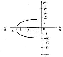
A control system has G(s)H(s)  (0 < K < ∞). The number of breakaway point in the root locus diagram is/are
- a)one
- b)two
- c)three
- d)none of these
Correct answer is option 'A'. Can you explain this answer?
A control system has G(s)H(s) (0 < K < ∞). The number of breakaway point in the root locus diagram is/are
(0 < K < ∞). The number of breakaway point in the root locus diagram is/area)
one
b)
two
c)
three
d)
none of these
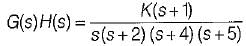
| | Sagarika Singh answered |
∴ Number of branches terminating at infinity = P - Z = 2.
Number of branches terminating at zero = Z = 1.
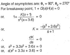
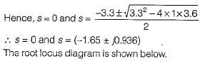
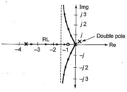
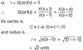
Here, (-1.65 ± j0.936) is not a part of root locus. Thus, it has only one breakaway point s = 0.
The open loop transfer function of a unity feedback control system is given by
The breakaway point in its root locus will lie between- a)0 and -1
- b)beyond - 5
- c)-4 and -5
- d)-2 and -4
Correct answer is option 'D'. Can you explain this answer?
The open loop transfer function of a unity feedback control system is given by
The breakaway point in its root locus will lie between
The breakaway point in its root locus will lie between
a)
0 and -1
b)
beyond - 5
c)
-4 and -5
d)
-2 and -4
| | Gargi Mishra answered |
Here, P=4,Z= 1, P-Z= 3
No. of branches of RL terminating at zero = 1.
No. of branches of RL terminatina at infinity = 3
Since out of the given option, real axis between s = -2 and s = -4 is only a part of root locus, therefore breakaway point will lie between -2 and -4.
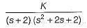
The breakaway point in the root loci plot for the loop transfer function G(s) = 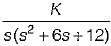 is
is- a)-1.5
- b)-2
- c)-1
- d)-2.2
Correct answer is option 'B'. Can you explain this answer?
The breakaway point in the root loci plot for the loop transfer function G(s) = is
isa)
-1.5
b)
-2
c)
-1
d)
-2.2
| | Charvi Reddy answered |
Given, 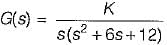
1+ G(s) = 0
or, s (s2+ 6 s + 12) + K = 0
or, K = - ( s3 + 6 s2 + 12s)
For B.A. points,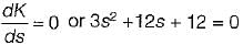
or, s2 + 4s + 4 = 0
or, (s + 2)2 = 0
or, s = - 2 , - 2
For given O.L.T.F., P = 3, Z - 0, P - Z = 3
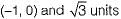
Poles are at s = 0 and s = -3 ± ;V3 =-3 ± j1.732
Since entire -ve real axis is a part of root locus, therefore s = -2 is a valid breakaway point.
1+ G(s) = 0
or, s (s2+ 6 s + 12) + K = 0
or, K = - ( s3 + 6 s2 + 12s)
For B.A. points,
or, s2 + 4s + 4 = 0
or, (s + 2)2 = 0
or, s = - 2 , - 2
For given O.L.T.F., P = 3, Z - 0, P - Z = 3
Poles are at s = 0 and s = -3 ± ;V3 =-3 ± j1.732
Since entire -ve real axis is a part of root locus, therefore s = -2 is a valid breakaway point.
Chapter doubts & questions for The Root Locus Technique - 3 Months Preparation for GATE Electrical 2026 is part of Electrical Engineering (EE) exam preparation. The chapters have been prepared according to the Electrical Engineering (EE) exam syllabus. The Chapter doubts & questions, notes, tests & MCQs are made for Electrical Engineering (EE) 2026 Exam. Find important definitions, questions, notes, meanings, examples, exercises, MCQs and online tests here.
Chapter doubts & questions of The Root Locus Technique - 3 Months Preparation for GATE Electrical in English & Hindi are available as part of Electrical Engineering (EE) exam. Download more important topics, notes, lectures and mock test series for Electrical Engineering (EE) Exam by signing up for free.
3 Months Preparation for GATE Electrical676 videos|1399 docs|882 tests |