


All Exams > Electrical Engineering (EE) > 3 Months Preparation for GATE Electrical > All Questions
All questions of Design of sampled data control systems for Electrical Engineering (EE) Exam
For minimum phase systems:- a)Pole must lie on left plane
- b)Zeroes must lie on left plane
- c)Poles and zeroes must lie on left plane
- d)Both must lie on right plane
Correct answer is option 'C'. Can you explain this answer?
For minimum phase systems:
a)
Pole must lie on left plane
b)
Zeroes must lie on left plane
c)
Poles and zeroes must lie on left plane
d)
Both must lie on right plane
| | Rajat Kumar answered |
Answer: c
Explanation: For minimum phase systems poles and zeroes must lie on the right s-plane.
Explanation: For minimum phase systems poles and zeroes must lie on the right s-plane.

The phase margin (in degrees) of a system having the loop transfer function G(s) H(s)=2√3/s(s+1) is: - a)45°
- b)-30°
- c)60°
- d)30°
Correct answer is option 'D'. Can you explain this answer?
The phase margin (in degrees) of a system having the loop transfer function G(s) H(s)=2√3/s(s+1) is:
a)
45°
b)
-30°
c)
60°
d)
30°
| | Sharmila Bajaj answered |
Answer: d
Explanation: Phase margin is calculated at gain cross over frequency where magnitude of the transfer function is 1.
Explanation: Phase margin is calculated at gain cross over frequency where magnitude of the transfer function is 1.
The loop transfer function of a system is given by G(s) H(s) =10e-Ls/s. The phase crossover frequency is 5rad/s. The value of the dead time L is- a)π/20
- b)π/10
- c)-π/20
- d)Zero
Correct answer is option 'B'. Can you explain this answer?
The loop transfer function of a system is given by G(s) H(s) =10e-Ls/s. The phase crossover frequency is 5rad/s. The value of the dead time L is
a)
π/20
b)
π/10
c)
-π/20
d)
Zero
| | Sravya Khanna answered |
Answer: b
Explanation: – π/2-180/π*L*5 = -π
5L =π/2
L =π/10.
Explanation: – π/2-180/π*L*5 = -π
5L =π/2
L =π/10.
The important figures of merit to the system in frequency domain are :- a)Maximum value of resonant peak
- b)Value of resonance frequency
- c)Maximum value of resonant peak and Value of resonance frequency
- d)Minimum value of resonance frequency
Correct answer is option 'C'. Can you explain this answer?
The important figures of merit to the system in frequency domain are :
a)
Maximum value of resonant peak
b)
Value of resonance frequency
c)
Maximum value of resonant peak and Value of resonance frequency
d)
Minimum value of resonance frequency
| | Isha Singh answered |
Answer: c
Explanation: The important figures of merit to the system in frequency domain are maximum value of resonance peak and frequency at which it occurs.
Explanation: The important figures of merit to the system in frequency domain are maximum value of resonance peak and frequency at which it occurs.
Consider the system represented by the equation given below. What would be the total phase value at ω = 0?
200/[s3 (s + 3) (s + 6) (s + 10)]. - a)-90°
- b)-180°
- c)-270°
- d)-360°
Correct answer is option 'C'. Can you explain this answer?
Consider the system represented by the equation given below. What would be the total phase value at ω = 0?
200/[s3 (s + 3) (s + 6) (s + 10)].
200/[s3 (s + 3) (s + 6) (s + 10)].
a)
-90°
b)
-180°
c)
-270°
d)
-360°
| | Mayank Sengupta answered |
Answer: c
Explanation: The phase can be calculated by the basic formula for calculating phase angle
Explanation: The phase can be calculated by the basic formula for calculating phase angle
Consider the function F (s) =5/s (s2+s+2) , where F (s) is the Laplace transform f (t). Then the final value theorem is equal to - a)5
- b)5/2
- c)Zero
- d)Infinity
Correct answer is option 'B'. Can you explain this answer?
Consider the function F (s) =5/s (s2+s+2) , where F (s) is the Laplace transform f (t). Then the final value theorem is equal to
a)
5
b)
5/2
c)
Zero
d)
Infinity
| | Sanvi Kapoor answered |
Answer: b
Explanation: Final value theorem is given for the stable system only and this is a type 1 system and for step input the final value can be calculated as 5/2.
Explanation: Final value theorem is given for the stable system only and this is a type 1 system and for step input the final value can be calculated as 5/2.
The angles of asymptotes of the root loci of the equation s3+5s2+(K+2)s+K=0 are: - a)0° and 270°
- b)0° and 180°
- c)90° and 270°
- d)90° and 180°
Correct answer is option 'C'. Can you explain this answer?
The angles of asymptotes of the root loci of the equation s3+5s2+(K+2)s+K=0 are:
a)
0° and 270°
b)
0° and 180°
c)
90° and 270°
d)
90° and 180°
| | Ravi Singh answered |
Answer: c
Explanation: P-Z =2
Angle of asymptote = (2q+1)180°/P-Z
Angle are 90° and 270°.
Explanation: P-Z =2
Angle of asymptote = (2q+1)180°/P-Z
Angle are 90° and 270°.
In a feedback control system, phase margin(PM) is
1. Directly proportional to G
2. Inversely proportional to G
3. Independent of G
4. Zero when G =0
Which of the above statements are correct?- a)1 and 2
- b)2 and 3
- c)3 and 4
- d)1 and 4
Correct answer is option 'D'. Can you explain this answer?
In a feedback control system, phase margin(PM) is
1. Directly proportional to G
2. Inversely proportional to G
3. Independent of G
4. Zero when G =0
Which of the above statements are correct?
1. Directly proportional to G
2. Inversely proportional to G
3. Independent of G
4. Zero when G =0
Which of the above statements are correct?
a)
1 and 2
b)
2 and 3
c)
3 and 4
d)
1 and 4
 | Harshad Iyer answered |
Understanding Phase Margin in Control Systems
Phase margin (PM) is a crucial parameter in feedback control systems that measures the stability of the system. Let's analyze the statements provided and explain why option 'D' is correct.
1. PM is directly proportional to G2
- This statement is incorrect. Phase margin is not directly proportional to the gain of the system components. Instead, it is influenced by the overall loop gain and the system's frequency response.
2. PM is inversely proportional to G3
- This statement is also incorrect. While gain affects the stability of the system, it's not a straightforward inverse relationship. PM can be affected by the gain but does not follow an inverse proportionality.
3. PM is independent of G4
- This statement is correct. Phase margin can be independent of certain gain elements in the system. For instance, if G4 pertains to a part of the system that does not contribute to the overall stability at the crossover frequency, it doesn’t influence the PM.
4. PM is zero when G = 0
- This statement is correct. If the gain G of the system is zero, the system cannot have any phase margin, as it implies that there is no feedback or control being applied, resulting in no stability.
Conclusion
Given the analysis, the correct statements are 3 and 4. Hence, the correct answer is option 'D'. These insights highlight the nuanced relationships between gain elements and phase margin in feedback control systems.
The roots of the characteristic equation of the second order system in which real and imaginary part represents the :- a)Damped frequency and damping
- b)Damping and damped frequency
- c)Natural frequency and damping ratio
- d)Damping ratio and natural frequency
Correct answer is option 'B'. Can you explain this answer?
The roots of the characteristic equation of the second order system in which real and imaginary part represents the :
a)
Damped frequency and damping
b)
Damping and damped frequency
c)
Natural frequency and damping ratio
d)
Damping ratio and natural frequency
| | Srishti Choudhary answered |
Answer: b
Explanation: Real part represents the damping and imaginary part damped frequency.
Explanation: Real part represents the damping and imaginary part damped frequency.
Laplace transform is used for the systems with:- a)Initial conditions infinite
- b)Initial conditions zero
- c)Initial conditions finite
- d)Initial conditions equal to the initial input
Correct answer is option 'B'. Can you explain this answer?
Laplace transform is used for the systems with:
a)
Initial conditions infinite
b)
Initial conditions zero
c)
Initial conditions finite
d)
Initial conditions equal to the initial input
| | Aniket Shah answered |
Answer: b
Explanation: By definition of the transfer function by Laplace transform the initial conditions of the systems are considered to be zero.
Explanation: By definition of the transfer function by Laplace transform the initial conditions of the systems are considered to be zero.
Scientist Bode have contribution in :- a)Asymptotic plots
- b)Polar plots
- c)Root locus technique
- d)Constant M and n circle
Correct answer is option 'A'. Can you explain this answer?
Scientist Bode have contribution in :
a)
Asymptotic plots
b)
Polar plots
c)
Root locus technique
d)
Constant M and n circle
| | Aashna Dey answered |
Answer: a
Explanation: Asymptotic plots are the bode plots that are drawn to find the relative stability of the system by finding the phase and gain margin and this was invented by Scientist Bode.
Explanation: Asymptotic plots are the bode plots that are drawn to find the relative stability of the system by finding the phase and gain margin and this was invented by Scientist Bode.
Which of the following is an electromechanical device?- a)Induction relay
- b)Thermocouple
- c)LVDT
- d)All of the mentioned
Correct answer is option 'C'. Can you explain this answer?
Which of the following is an electromechanical device?
a)
Induction relay
b)
Thermocouple
c)
LVDT
d)
All of the mentioned
| | Jatin Mukherjee answered |
Answer: c
Explanation: LVDT is the electromechanical device which converts the displacement of the core to the electrical energy by the action of the transformer.
Explanation: LVDT is the electromechanical device which converts the displacement of the core to the electrical energy by the action of the transformer.
Cut-off rate is the ability of the system to distinguish the signal from _____________- a)Bandwidth
- b)Noise
- c)Resonance peak
- d)Magnitude
Correct answer is option 'B'. Can you explain this answer?
Cut-off rate is the ability of the system to distinguish the signal from _____________
a)
Bandwidth
b)
Noise
c)
Resonance peak
d)
Magnitude
| | Neha Nambiar answered |
Answer: b
Explanation: Cut-off rate is the ability of the system to distinguish the signal from noise.
Explanation: Cut-off rate is the ability of the system to distinguish the signal from noise.
Frequency range of bode magnitude and phases are decided by :- a)The lowest and higher important frequencies of dominant factors of the OLTF
- b)The lowest and highest important frequencies of all the factors of the open loop transfer function
- c)Resonant frequencies of the second factors
- d)None of the above
Correct answer is option 'D'. Can you explain this answer?
Frequency range of bode magnitude and phases are decided by :
a)
The lowest and higher important frequencies of dominant factors of the OLTF
b)
The lowest and highest important frequencies of all the factors of the open loop transfer function
c)
Resonant frequencies of the second factors
d)
None of the above
| | Kalyan Patel answered |
Answer: d
Explanation: T. F. = Kp (1+Tds)
There is only one zero which will give slope of +20dB/decade.
Explanation: T. F. = Kp (1+Tds)
There is only one zero which will give slope of +20dB/decade.
The transfer function of a system is given by Y(s)/X(s) = e−0.1s/1+s. If x(t) is 0.5sint, then the phase angle between the output and the input will be: - a)-39.27°
- b)-45°
- c)-50.73°
- d)-90°
Correct answer is option 'C'. Can you explain this answer?
The transfer function of a system is given by Y(s)/X(s) = e−0.1s/1+s. If x(t) is 0.5sint, then the phase angle between the output and the input will be:
a)
-39.27°
b)
-45°
c)
-50.73°
d)
-90°
| | Dishani Bose answered |
Answer: c
Explanation: Phase angle = -tan−1-0.1*180°/π
w =1 rad/sec
Phase angle =-50.73°.
Explanation: Phase angle = -tan−1-0.1*180°/π
w =1 rad/sec
Phase angle =-50.73°.
______________technique gives quick transient and stability response- a)Root locus
- b)Bode
- c)Nyquist
- d)Nichols
Correct answer is option 'A'. Can you explain this answer?
______________technique gives quick transient and stability response
a)
Root locus
b)
Bode
c)
Nyquist
d)
Nichols
| | Nitin Chawla answered |
Answer: a
Explanation: Root locus is the right technique for the quick transient and stability response and gives the final response and quickly.
Explanation: Root locus is the right technique for the quick transient and stability response and gives the final response and quickly.
The critical value of gain for a system is 40 and gain margin is 6dB. The system is operating at a gain of:- a)20
- b)40
- c)80
- d)120
Correct answer is option 'A'. Can you explain this answer?
The critical value of gain for a system is 40 and gain margin is 6dB. The system is operating at a gain of:
a)
20
b)
40
c)
80
d)
120
| | Dipanjan Nambiar answered |
The solution to your question is:
Gm (dB) = 20logGM
GM =2
As we know, GM =K (marginal)/K (desired)
K desired =40/2 =20.
Hence, the Correct Answer is Option A
You can attempt more such questions by going through the link:
Gm (dB) = 20logGM
GM =2
As we know, GM =K (marginal)/K (desired)
K desired =40/2 =20.
Hence, the Correct Answer is Option A
You can attempt more such questions by going through the link:

If the gain of the system is reduced to a zero value, the roots of the system in the s-plane,- a)Coincide with zero
- b)Move away from zero
- c)Move away from poles
- d)Coincide with the poles
Correct answer is option 'D'. Can you explain this answer?
If the gain of the system is reduced to a zero value, the roots of the system in the s-plane,
a)
Coincide with zero
b)
Move away from zero
c)
Move away from poles
d)
Coincide with the poles
| | Divya Singh answered |
Answer: d
Explanation: The roots of the system in s plane coincides with the poles if the gain of the system is reduced to a value zero.
Explanation: The roots of the system in s plane coincides with the poles if the gain of the system is reduced to a value zero.
The open loop transfer function of a system is :G(s) H(s) =K/ (1+s) (1+2s) (1+3s)The phase crossover frequency wpc is:- a)√2
- b)1
- c)Zero
- d)√3
Correct answer is option 'B'. Can you explain this answer?
The open loop transfer function of a system is :G(s) H(s) =K/ (1+s) (1+2s) (1+3s)
The phase crossover frequency wpc is:
a)
√2
b)
1
c)
Zero
d)
√3
| | Jaya Dasgupta answered |
Answer: b
Explanation: angle =-180°
3wpc/1-2wpc2 =-3wpc
wpc = 1 rad/sec.
Explanation: angle =-180°
3wpc/1-2wpc2 =-3wpc
wpc = 1 rad/sec.
Given a unity feedback control system with G (s) = K/s(s+4), the value of K for which the damping ratio is 0.5.- a)1
- b)16
- c)64
- d)32
Correct answer is option 'B'. Can you explain this answer?
Given a unity feedback control system with G (s) = K/s(s+4), the value of K for which the damping ratio is 0.5.
a)
1
b)
16
c)
64
d)
32
| | Anoushka Choudhury answered |
Answer: b
Explanation: The value is found by using the Routh- Hurwitz criteria and equating one of the row of the Routh-Hurwitz criteria equal to zero and hence finding the value of K.
Explanation: The value is found by using the Routh- Hurwitz criteria and equating one of the row of the Routh-Hurwitz criteria equal to zero and hence finding the value of K.
Determine the centroid of the root locus for the system having G(s)H(s) = K/(s+1)(s2+4s+5) - a)-2.1
- b)-1.78
- c)-1.66
- d)-1.06
Correct answer is option 'C'. Can you explain this answer?
Determine the centroid of the root locus for the system having G(s)H(s) = K/(s+1)(s2+4s+5)
a)
-2.1
b)
-1.78
c)
-1.66
d)
-1.06
| | Divya Nair answered |
Answer: Roots of the open loop transfer function are -1,-2+j, -2-j then centroid =Σreal part of open loop pole-Σreal part of open loop zeroes/P-Z
Centroid =(-1-2-2)-0/3 =-5/3 =-1.66.
Centroid =(-1-2-2)-0/3 =-5/3 =-1.66.
If a Nyquist plot of G (jω) H (jω) for a closed loop system passes through (-2, j0) point in GH plane, what would be the value of gain margin of the system in dB?- a)0 dB
- b)2.0201 dB
- c)4 dB
- d)6.0205 dB
Correct answer is option 'D'. Can you explain this answer?
If a Nyquist plot of G (jω) H (jω) for a closed loop system passes through (-2, j0) point in GH plane, what would be the value of gain margin of the system in dB?
a)
0 dB
b)
2.0201 dB
c)
4 dB
d)
6.0205 dB
| | Ashwin Kapoor answered |
Answer: d
Explanation: Gain Margin is calculated by taking inverse of the gain where the Nyquist plot cuts the real axis.
Explanation: Gain Margin is calculated by taking inverse of the gain where the Nyquist plot cuts the real axis.
If a system has an open loop transfer function1-s / 1+s, then the gain of the system at frequency of 1 rad/s will be- a)1
- b)1/2
- c)Zero
- d)-1
Correct answer is option 'D'. Can you explain this answer?
If a system has an open loop transfer function1-s / 1+s, then the gain of the system at frequency of 1 rad/s will be
a)
1
b)
1/2
c)
Zero
d)
-1
| | Anoushka Kumar answered |
Answer: d
Explanation: The system is all pass system and the gain of the system at frequency of 1 rad/sec.
Explanation: The system is all pass system and the gain of the system at frequency of 1 rad/sec.
When the number of poles is equal to the number of zeroes, how many branches of root locus tends towards infinity?- a)1
- b)2
- c)0
- d)Equal to number of zeroes
Correct answer is option 'C'. Can you explain this answer?
When the number of poles is equal to the number of zeroes, how many branches of root locus tends towards infinity?
a)
1
b)
2
c)
0
d)
Equal to number of zeroes
| | Sharmila Kulkarni answered |
Answer: c
Explanation: Branches of the root locus is equal to the number of poles or zeroes which ever is greater and tends toward infinity when poles or zeroes are unequal.
Explanation: Branches of the root locus is equal to the number of poles or zeroes which ever is greater and tends toward infinity when poles or zeroes are unequal.
Which one of the following statements is correct for gain margin and phase margin of two closed-loop systems having loop functions G(s) H(s) and exp(-s) G(s) H(s)?- a)Both gain and phase margins of the two systems will be identical
- b)Both gain and phase margins of G(s) H(s) will be more
- c)Gain margins of the two systems are the same but phase margins of G(s) H(s) will be more
- d)Phase margins of the two systems are the same but gain margin of G(s) H(s) will be less
Correct answer is option 'C'. Can you explain this answer?
Which one of the following statements is correct for gain margin and phase margin of two closed-loop systems having loop functions G(s) H(s) and exp(-s) G(s) H(s)?
a)
Both gain and phase margins of the two systems will be identical
b)
Both gain and phase margins of G(s) H(s) will be more
c)
Gain margins of the two systems are the same but phase margins of G(s) H(s) will be more
d)
Phase margins of the two systems are the same but gain margin of G(s) H(s) will be less
| | Raj Desai answered |
Answer: c
Explanation: The factor exp (-st) is the cause of the term transportation lag (time delay). The effect of e-st term is simply to rotate each point of the G(s) H(s) plot by an angle wT rad in the clockwise direction. So the phase margin of the system reduces as T increases. But since |e-s| =1, therefore the gain margins of both the systems are the same.
Explanation: The factor exp (-st) is the cause of the term transportation lag (time delay). The effect of e-st term is simply to rotate each point of the G(s) H(s) plot by an angle wT rad in the clockwise direction. So the phase margin of the system reduces as T increases. But since |e-s| =1, therefore the gain margins of both the systems are the same.
How can the steady state error can be reduced?- a)By decreasing the type of the system
- b)By increasing the input
- c)By decreasing the static error constant
- d)By increasing system gain
Correct answer is option 'D'. Can you explain this answer?
How can the steady state error can be reduced?
a)
By decreasing the type of the system
b)
By increasing the input
c)
By decreasing the static error constant
d)
By increasing system gain
| | Prisha Sengupta answered |
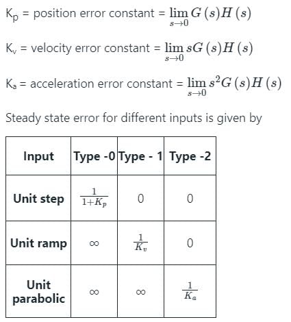
From the above table, it is clear that for type – 1 system, a system shows zero steady-state error for step-input, finite steady-state error for Ramp-input and ∞ steady-state error for parabolic-input.
As the type of the system increases, the steady-state error decreases.
The steady-state error is inversely proportional to the gain. Therefore, it can be reduced by increasing the system gain.
The forward path transfer function of a unity feedback system is given by G(s) = 1/(1+s)^2.
What is the phase margin of the system? - a)–π rad
- b)0 rad
- c)π/2 rad
- d)π rad
Correct answer is option 'D'. Can you explain this answer?
The forward path transfer function of a unity feedback system is given by G(s) = 1/(1+s)^2.
What is the phase margin of the system?
What is the phase margin of the system?
a)
–π rad
b)
0 rad
c)
π/2 rad
d)
π rad
| | Rahul Chakraborty answered |
Answer: d
Explanation: Magnitude at gain cross over frequency is 1 and PM is π rad.
Explanation: Magnitude at gain cross over frequency is 1 and PM is π rad.
For a stable closed loop system, the gain at phase crossover frequency should always be:- a)< 20 dB
- b)< 6 dB
- c)> 6 dB
- d)> 0 dB
Correct answer is option 'D'. Can you explain this answer?
For a stable closed loop system, the gain at phase crossover frequency should always be:
a)
< 20 dB
b)
< 6 dB
c)
> 6 dB
d)
> 0 dB
| | Bhavana Reddy answered |
Answer: d
Explanation: Phase crossover frequency is the frequency at which the gain of the system must be 1 and for a stable system the gain is decibels must be 0 db.
Explanation: Phase crossover frequency is the frequency at which the gain of the system must be 1 and for a stable system the gain is decibels must be 0 db.
The constant M-circle represented by the equation x^2+2.25x+y^2=-1.25 has the value of M equal to: - a)1
- b)2
- c)3
- d)4
Correct answer is option 'C'. Can you explain this answer?
The constant M-circle represented by the equation x^2+2.25x+y^2=-1.25 has the value of M equal to:
a)
1
b)
2
c)
3
d)
4
| | Avik Iyer answered |
Answer: c
Explanation: Comparing with the M circle equation we have the value of M =3.
Explanation: Comparing with the M circle equation we have the value of M =3.
Constant M- loci:- a)Constant gain and constant phase shift loci of the closed-loop system.
- b)Plot of loop gain with the variation in frequency
- c)Circles of constant gain for the closed loop transfer function
- d)Circles of constant phase shift for the closed loop transfer function
Correct answer is option 'D'. Can you explain this answer?
Constant M- loci:
a)
Constant gain and constant phase shift loci of the closed-loop system.
b)
Plot of loop gain with the variation in frequency
c)
Circles of constant gain for the closed loop transfer function
d)
Circles of constant phase shift for the closed loop transfer function
| | Sravya Khanna answered |
Answer: d
Explanation: By definition, Constant M loci are Circles of constant phase shift for the closed loop transfer function.
Explanation: By definition, Constant M loci are Circles of constant phase shift for the closed loop transfer function.
The impulse response of a LTI system is a unit step function, then the corresponding transfer function is- a)1/s
- b)1/s2
- c)1
- d)s
Correct answer is option 'A'. Can you explain this answer?
The impulse response of a LTI system is a unit step function, then the corresponding transfer function is
a)
1/s
b)
1/s2
c)
1
d)
s
| | Avantika Kaur answered |
Answer: a
Explanation: The impulse response of a LTI system is the transfer function itself and hence for the unit step function . As input then the transfer function will be 1/s.
Explanation: The impulse response of a LTI system is the transfer function itself and hence for the unit step function . As input then the transfer function will be 1/s.
When the period of the observation is large, the type of the error will be:- a)Transient error
- b)Steady state error
- c)Half-power error
- d)Position error constant
Correct answer is option 'B'. Can you explain this answer?
When the period of the observation is large, the type of the error will be:
a)
Transient error
b)
Steady state error
c)
Half-power error
d)
Position error constant
| | Maulik Chatterjee answered |
Answer: b
Explanation: The error will be the steady state error if the period of observation is large as the time if large then the final value theorem can be directly applied.
Explanation: The error will be the steady state error if the period of observation is large as the time if large then the final value theorem can be directly applied.
The gain margin in dBs of a unity feedback control system whose open loop transfer function, G(s) H(s) =1/s(s+1) is - a)0
- b)1
- c)-1
- d)∞
Correct answer is option 'D'. Can you explain this answer?
The gain margin in dBs of a unity feedback control system whose open loop transfer function, G(s) H(s) =1/s(s+1) is
a)
0
b)
1
c)
-1
d)
∞
| | Nandita Kulkarni answered |
Answer: d
Explanation: wpc = ∞
Magnitude of the transfer function =0
Gain Margin =∞ dB.
Explanation: wpc = ∞
Magnitude of the transfer function =0
Gain Margin =∞ dB.
Constant N-loci:- a)Constant gain and constant phase shift loci of the closed-loop system.
- b)Plot of loop gain with the variation in frequency
- c)Circles of constant gain for the closed loop transfer function
- d)Circles of constant phase shift for the closed loop transfer function
Correct answer is option 'C'. Can you explain this answer?
Constant N-loci:
a)
Constant gain and constant phase shift loci of the closed-loop system.
b)
Plot of loop gain with the variation in frequency
c)
Circles of constant gain for the closed loop transfer function
d)
Circles of constant phase shift for the closed loop transfer function
| | Gaurav Chauhan answered |
Answer: c
Explanation: Constant N loci are the circles of constant gain for the closed loop transfer function and the intersection point of the M and N is always the point (-1,0).
Explanation: Constant N loci are the circles of constant gain for the closed loop transfer function and the intersection point of the M and N is always the point (-1,0).
A polar plot intersects the unit circle at a point making -45° to the negative real axis then the phase margin of the system is : - a)-45°
- b)45°
- c)180°-45°
- d)180°+45°
Correct answer is option 'B'. Can you explain this answer?
A polar plot intersects the unit circle at a point making -45° to the negative real axis then the phase margin of the system is :
a)
-45°
b)
45°
c)
180°-45°
d)
180°+45°
| | Hiral Kulkarni answered |
Answer: b
Explanation: As the angle is with the negative real axis hence the Phase margin will be 45°.
Explanation: As the angle is with the negative real axis hence the Phase margin will be 45°.
The frequency at which the Nyquist diagram cuts the unit circle is known as:- a)Gain crossover frequency
- b)Phase crossover frequency
- c)Damping frequency
- d)Corner frequency
Correct answer is option 'A'. Can you explain this answer?
The frequency at which the Nyquist diagram cuts the unit circle is known as:
a)
Gain crossover frequency
b)
Phase crossover frequency
c)
Damping frequency
d)
Corner frequency
| | Mayank Sengupta answered |
Answer: a
Explanation: The frequency at which the Nyquist diagram cuts the unit circle is known as gain cross over frequency.
Explanation: The frequency at which the Nyquist diagram cuts the unit circle is known as gain cross over frequency.
The addition of open loop poles pulls the root locus towards:- a)The right and system becomes unstable
- b)Imaginary axis and system becomes marginally stable
- c)The left and system becomes unstable
- d)The right and system becomes unstable
Correct answer is option 'D'. Can you explain this answer?
The addition of open loop poles pulls the root locus towards:
a)
The right and system becomes unstable
b)
Imaginary axis and system becomes marginally stable
c)
The left and system becomes unstable
d)
The right and system becomes unstable
| | Sahil Datta answered |
Answer: d
Explanation: The addition of open loop poles pulls the root locus towards the right and system becomes unstable.
Explanation: The addition of open loop poles pulls the root locus towards the right and system becomes unstable.
In second order system gain margin is :- a)Zero value
- b)Finite value
- c)Infinite value
- d)None of the mentioned
Correct answer is option 'C'. Can you explain this answer?
In second order system gain margin is :
a)
Zero value
b)
Finite value
c)
Infinite value
d)
None of the mentioned
| | Arpita Banerjee answered |
Answer: c
Explanation: Gain margin is defined generally for systems with order greater than 3.
Explanation: Gain margin is defined generally for systems with order greater than 3.
A minimum phase unity feedback system has a bode plot with a constant slope of -20dB/decade for all frequencies. What is the value of the maximum phase margins of the system? - a)0°
- b)90°
- c)-90°
- d)180°
Correct answer is option 'B'. Can you explain this answer?
A minimum phase unity feedback system has a bode plot with a constant slope of -20dB/decade for all frequencies. What is the value of the maximum phase margins of the system?
a)
0°
b)
90°
c)
-90°
d)
180°
| | Athul Banerjee answered |
Answer: b
Explanation: For given Bode plot, G(s) H(s) =K/jw
As H(s) =1
PM (maximum) =90°.
Explanation: For given Bode plot, G(s) H(s) =K/jw
As H(s) =1
PM (maximum) =90°.
For the transfer functionG(s) H(s) = 1 / s(s+1) (s+0.5), the phase cross-over frequency is- a)0.5 rad/sec
- b)0.707 rad/sec
- c)1.732 rad/sec
- d)2 rad/sec
Correct answer is option 'B'. Can you explain this answer?
For the transfer function
G(s) H(s) = 1 / s(s+1) (s+0.5), the phase cross-over frequency is
a)
0.5 rad/sec
b)
0.707 rad/sec
c)
1.732 rad/sec
d)
2 rad/sec
| | Shivam Ghosh answered |
Answer: b
Explanation: Phase cross over frequency is calculated at the point where magnitude of the polar plot is 1.
Explanation: Phase cross over frequency is calculated at the point where magnitude of the polar plot is 1.
Root locus is used to calculate:- a)Marginal stability
- b)Absolute stability
- c)Conditional stability
- d)Relative stability
Correct answer is option 'D'. Can you explain this answer?
Root locus is used to calculate:
a)
Marginal stability
b)
Absolute stability
c)
Conditional stability
d)
Relative stability
| | Prasenjit Yadav answered |
Answer: d
Explanation: Root locus is used to calculate relative stability.
Explanation: Root locus is used to calculate relative stability.
Which one of the following are correct?The root locus is the path of the roots of the characteristic equation traced out in the s-plane?- a)As the input of the system is changed
- b)As the output of the system is changed
- c)As a system parameter is changed
- d)As the sensitivity is changed
Correct answer is option 'C'. Can you explain this answer?
Which one of the following are correct?The root locus is the path of the roots of the characteristic equation traced out in the s-plane?
a)
As the input of the system is changed
b)
As the output of the system is changed
c)
As a system parameter is changed
d)
As the sensitivity is changed
| | Pranjal Datta answered |
Answer: c
Explanation: The root locus is the locus of the change of the system parameters of the characteristic equation traced out in the s-plane.
Explanation: The root locus is the locus of the change of the system parameters of the characteristic equation traced out in the s-plane.
With negative feedback in a closed loop control system, the system sensitivity to parameter variation:- a)Increases
- b)Decreases
- c)Becomes zero
- d)Becomes infinite
Correct answer is option 'B'. Can you explain this answer?
With negative feedback in a closed loop control system, the system sensitivity to parameter variation:
a)
Increases
b)
Decreases
c)
Becomes zero
d)
Becomes infinite
| | Mahi Bose answered |
Answer: b
Explanation: Sensitivity is defined as the change in the output with respect to the change in the input and due to negative feedback reduces by a factor of 1/ (1+GH).
Explanation: Sensitivity is defined as the change in the output with respect to the change in the input and due to negative feedback reduces by a factor of 1/ (1+GH).
A third order system is approximated to an equivalent second order system. The rise time of this approximated lower order system will be:- a)Same as the original system for any input
- b)Smaller than the original system for any input
- c)Larger than the original system for any input
- d)Larger or smaller depending on the input
Correct answer is option 'B'. Can you explain this answer?
A third order system is approximated to an equivalent second order system. The rise time of this approximated lower order system will be:
a)
Same as the original system for any input
b)
Smaller than the original system for any input
c)
Larger than the original system for any input
d)
Larger or smaller depending on the input
| | Mansi Choudhury answered |
Answer: b
Explanation: As order of the system increases the system approaches more towards the ideal characteristics and if the third order system is approximated to an equivalent second order system then the rise time of this will be smaller than the original system for any input.
Explanation: As order of the system increases the system approaches more towards the ideal characteristics and if the third order system is approximated to an equivalent second order system then the rise time of this will be smaller than the original system for any input.
For Nyquist contour, the size of radius is _______- a)25
- b)0
- c)1
- d)∞
Correct answer is option 'D'. Can you explain this answer?
For Nyquist contour, the size of radius is _______
a)
25
b)
0
c)
1
d)
∞
| | Anjali Choudhury answered |
Answer: d
Explanation: For Nyquist contour, the size of radius is ∞.
Explanation: For Nyquist contour, the size of radius is ∞.
Which one of the following methods can determine the closed loop system resonance frequency operation?- a)Root locus method
- b)Nyquist method
- c)Bode plot
- d)M and N circle
Correct answer is option 'D'. Can you explain this answer?
Which one of the following methods can determine the closed loop system resonance frequency operation?
a)
Root locus method
b)
Nyquist method
c)
Bode plot
d)
M and N circle
| | Nilanjan Saini answered |
Answer: d
Explanation: Closed loop system resonance frequency is the frequency at which maximum peak occurs and this frequency of operation can best be determined with the help of M and N circle.
Explanation: Closed loop system resonance frequency is the frequency at which maximum peak occurs and this frequency of operation can best be determined with the help of M and N circle.
If a feedback control system has its open loop transfer function G(s)H(s) = K/(s-2)(s2+3s+5) has the root locus plot which intersects the imaginary axis at s =0, then the value of K at this point will be - a)-5
- b)10
- c)5
- d)-10
Correct answer is option 'B'. Can you explain this answer?
If a feedback control system has its open loop transfer function G(s)H(s) = K/(s-2)(s2+3s+5) has the root locus plot which intersects the imaginary axis at s =0, then the value of K at this point will be
a)
-5
b)
10
c)
5
d)
-10
| | Sandeep Saha answered |
Answer: b
Explanation: The intersection point on the imaginary axis at s =0 is obtained by Routh Hurwitz criteria making s^0 row zero and getting the value K = 10.
Explanation: The intersection point on the imaginary axis at s =0 is obtained by Routh Hurwitz criteria making s^0 row zero and getting the value K = 10.
The corner frequencies are- a)0 and 1
- b)0 and 2
- c)0 and 1
- d)1 and 2
Correct answer is option 'D'. Can you explain this answer?
The corner frequencies are
a)
0 and 1
b)
0 and 2
c)
0 and 1
d)
1 and 2
| | Pranjal Datta answered |
Answer: d
Explanation: Corner frequency can be calculated by time constant form of the transfer function and here the corner frequencies are 1 and 2.
Explanation: Corner frequency can be calculated by time constant form of the transfer function and here the corner frequencies are 1 and 2.
If the gain of the critical damped system is increased it will behave as- a)Oscillatory
- b)Critically damped
- c)Overdamped
- d)Underdamped
Correct answer is option 'A'. Can you explain this answer?
If the gain of the critical damped system is increased it will behave as
a)
Oscillatory
b)
Critically damped
c)
Overdamped
d)
Underdamped
| | Harshad Singh answered |
Answer: a
Explanation: On increasing the gain damping will automatically get reduced and hence the oscillations in the system increases.
Explanation: On increasing the gain damping will automatically get reduced and hence the oscillations in the system increases.
The polar plot of the open loop transfer function of a feedback control system intersects the real axis at -2. The gain margin of the system is- a)-5dB
- b)0dB
- c)-6dB
- d)40dB
Correct answer is option 'C'. Can you explain this answer?
The polar plot of the open loop transfer function of a feedback control system intersects the real axis at -2. The gain margin of the system is
a)
-5dB
b)
0dB
c)
-6dB
d)
40dB
| | Saumya Sen answered |
Answer: c
Explanation: Gain margin of the system is inverse of the intersect on the real axis and calculated in decibels.
G(s) = 1+s / s(1+0.5s).
Explanation: Gain margin of the system is inverse of the intersect on the real axis and calculated in decibels.
G(s) = 1+s / s(1+0.5s).
Chapter doubts & questions for Design of sampled data control systems - 3 Months Preparation for GATE Electrical 2026 is part of Electrical Engineering (EE) exam preparation. The chapters have been prepared according to the Electrical Engineering (EE) exam syllabus. The Chapter doubts & questions, notes, tests & MCQs are made for Electrical Engineering (EE) 2026 Exam. Find important definitions, questions, notes, meanings, examples, exercises, MCQs and online tests here.
Chapter doubts & questions of Design of sampled data control systems - 3 Months Preparation for GATE Electrical in English & Hindi are available as part of Electrical Engineering (EE) exam. Download more important topics, notes, lectures and mock test series for Electrical Engineering (EE) Exam by signing up for free.
3 Months Preparation for GATE Electrical676 videos|1399 docs|882 tests |