


All Exams > Electrical Engineering (EE) > 3 Months Preparation for GATE Electrical > All Questions
All questions of Instrument Transformers for Electrical Engineering (EE) Exam
Turns ration for a C.T. is _________- a)n = Np ⁄ Ns
- b)n = Ns ⁄ Np
- c)n = 1 ⁄ Np
- d)n = Ns
Correct answer is option 'B'. Can you explain this answer?
Turns ration for a C.T. is _________
a)
n = Np ⁄ Ns
b)
n = Ns ⁄ Np
c)
n = 1 ⁄ Np
d)
n = Ns
 | Pioneer Academy answered |
The turns ratio for a C.T. is defined as the ratio of the number of turns in the secondary to the number of turns in the primary. It is given by the relation


The below symbol which is used in single line diagrams represents ________
- a)current transformer
- b)circuit breaker
- c)potential transformer
- d)power transformer
Correct answer is option 'C'. Can you explain this answer?
The below symbol which is used in single line diagrams represents ________
a)
current transformer
b)
circuit breaker
c)
potential transformer
d)
power transformer
 | Naroj Boda answered |
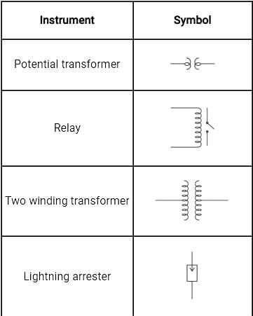
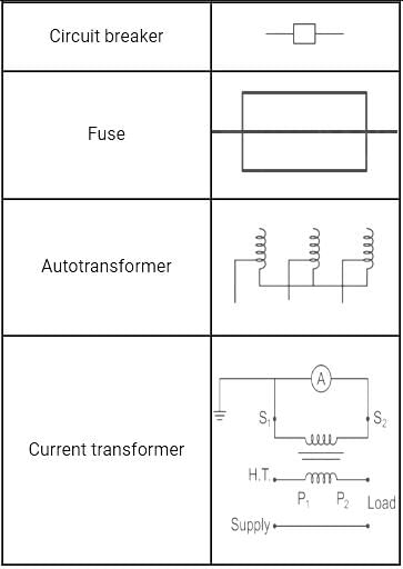
The symbols of different equipment used in single line diagram are shown below.
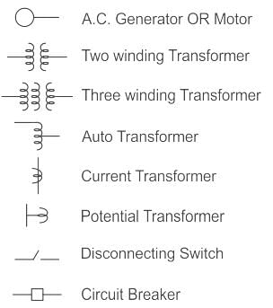
Hence, the given symbol is for the potential transformer.
Under operating conditions, the secondary of a current transformer is always short-circuited because of ________.- a)It protects the primary circuits
- b)It is safe to human beings
- c)It avoids core saturation and high voltage induction
- d)None of these
Correct answer is option 'C'. Can you explain this answer?
Under operating conditions, the secondary of a current transformer is always short-circuited because of ________.
a)
It protects the primary circuits
b)
It is safe to human beings
c)
It avoids core saturation and high voltage induction
d)
None of these
| | Pooja Patel answered |
The secondary side of the current transformer is always kept short-circuited in order to avoid core saturation and high voltage induction so that the current transformer can be used to measure high values of currents.
- Current transformer works on the principle of shorted secondary
- It means that the burden on the system Zb is equal to 0
- Thus, the current transformer produces a current in its secondary which is proportional to the current in its primary
A 5A ammeter can measure a current of upto 1000 A using a _________- a)5/1000A C.T.
- b)1000A C.T.
- c)5A C.T.
- d)1000/5A C.T.
Correct answer is option 'D'. Can you explain this answer?
A 5A ammeter can measure a current of upto 1000 A using a _________
a)
5/1000A C.T.
b)
1000A C.T.
c)
5A C.T.
d)
1000/5A C.T.
| | Sanskriti Desai answered |
Answer:
Explanation:
In order to measure a high current of 1000 A using a 5A ammeter, a current transformer (C.T.) is required. A current transformer is a device that steps down the high current to a lower value that can be measured by the ammeter.
The correct option is D, which states a 1000/5A C.T. This means that the current transformer steps down the primary current of 1000 A to a secondary current of 5 A.
Here's a detailed explanation of each option:
a) 5/1000A C.T.: This option suggests a current transformer that steps down the primary current of 5 A to a secondary current of 1000 A. However, we need to measure a high current of 1000 A, so this option is incorrect.
b) 1000A C.T.: This option suggests a current transformer that does not step down the primary current. It means that the primary current is equal to the secondary current. However, our ammeter can only measure up to 5A, so this option is incorrect.
c) 5A C.T.: This option suggests a current transformer that steps down the primary current of 5 A to a secondary current of 5 A. However, we need to measure a high current of 1000 A, so this option is incorrect.
d) 1000/5A C.T.: This option suggests a current transformer that steps down the primary current of 1000 A to a secondary current of 5 A. This is the correct option because it allows us to measure the high current of 1000 A using the 5A ammeter.
To summarize, in order to measure a high current of 1000 A using a 5A ammeter, a 1000/5A current transformer is required. This current transformer steps down the primary current of 1000 A to a secondary current of 5 A, which can be measured by the ammeter.
C.T. and P.T. are standardized at _________- a)50 A and 220 V
- b)25 mA and 2.2 kV
- c)5 A and 110 V
- d)75 nA and 1.1 MV
Correct answer is option 'C'. Can you explain this answer?
C.T. and P.T. are standardized at _________
a)
50 A and 220 V
b)
25 mA and 2.2 kV
c)
5 A and 110 V
d)
75 nA and 1.1 MV
| | Palak Verma answered |
The correct answer for the standardized values of C.T. (Current Transformer) and P.T. (Potential Transformer) is option 'C', which is 5 A and 110 V.
**Explanation:**
**Current Transformer (C.T.):**
- A Current Transformer is a type of instrument transformer used to measure alternating current (AC) in high voltage power systems.
- It steps down the high current flowing through the primary winding to a lower value suitable for measurement by instruments or protection relays.
- The secondary current of a C.T. is standardized at a particular value to ensure accuracy and compatibility with other devices in the power system.
- The standardized current rating for C.T. is typically 5 A for most applications.
- This means that when 5 A flows through the primary winding of the C.T., a proportional current of 5 A is obtained at the secondary winding.
**Potential Transformer (P.T.):**
- A Potential Transformer is another type of instrument transformer used to measure voltage in high voltage power systems.
- It steps down the high voltage to a lower value suitable for measurement by instruments or protection relays.
- The secondary voltage of a P.T. is standardized at a particular value to ensure accuracy and compatibility with other devices in the power system.
- The standardized voltage rating for P.T. is typically 110 V for most applications.
- This means that when 110 V is applied to the primary winding of the P.T., a proportional voltage of 110 V is obtained at the secondary winding.
**Why option 'C' is the correct answer:**
- Option 'C' states that C.T. and P.T. are standardized at 5 A and 110 V, respectively.
- This matches the standardized values commonly used for C.T.s and P.T.s in electrical power systems.
- The other options do not match the commonly standardized values and hence are incorrect.
- For example, option 'A' suggests that C.T. is standardized at 50 A, which is not a commonly used value.
- Similarly, option 'B' suggests that P.T. is standardized at 2.2 kV, which is also not a commonly used value.
- Option 'D' suggests extremely low current and extremely high voltage values, which are not practical for C.T.s and P.T.s in power systems.
Therefore, the correct answer is option 'C', which states that C.T. and P.T. are standardized at 5 A and 110 V, respectively.
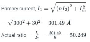
A current transformer has double turn primary and a 100 turn secondary winding. The secondary draws current of 6 A and magnetising ampere-turns is 60 A. What is actual transformation ratio?- a)100.5
- b)101
- c)50.24
- d)25.12
Correct answer is option 'C'. Can you explain this answer?
A current transformer has double turn primary and a 100 turn secondary winding. The secondary draws current of 6 A and magnetising ampere-turns is 60 A. What is actual transformation ratio?
a)
100.5
b)
101
c)
50.24
d)
25.12
| | Pooja Patel answered |
Magnetizing ampere-turns = 60 A = NI
Magnetizing current (Im) = 30 A
Number of primary turns (N1) = 2
Number of secondary turns (N2) = 100

Magnetizing current (Im) = 30 A
Number of primary turns (N1) = 2
Number of secondary turns (N2) = 100
Exciting current (I0) = Im = 30 A
The rated secondary current (I2) = 6 A
Reflected secondary current = nI2 = 50 x 6 = 300 A
The primary winding of a P.T. has _________- a)intermediate number of turns
- b)no turns at all
- c)a larger number of turns
- d)a few turns
Correct answer is option 'C'. Can you explain this answer?
The primary winding of a P.T. has _________
a)
intermediate number of turns
b)
no turns at all
c)
a larger number of turns
d)
a few turns
| | Pooja Patel answered |
The primary winding of a P.T. has a very large number of turns. It is connected in parallel with the load whose voltage is to be measured.
Instrument transformers provide _________- a)electrical isolation from low rated winding
- b)electrical isolation from high rated winding
- c)electrical isolation from medium rated winding
- d)no electrical isolation at all
Correct answer is option 'B'. Can you explain this answer?
Instrument transformers provide _________
a)
electrical isolation from low rated winding
b)
electrical isolation from high rated winding
c)
electrical isolation from medium rated winding
d)
no electrical isolation at all
| | Pooja Patel answered |
In an instrument transformer, the low rated secondary windings provide electrical isolation from the high rated primary windings.
A current carrying conductor is wrapped eight times around the jaw of a clamp-on meter that reads 50 A. What will be the actual value of the conductor current?- a)400 A
- b)6.25 A
- c)50 A
- d)12.5 A
Correct answer is option 'B'. Can you explain this answer?
A current carrying conductor is wrapped eight times around the jaw of a clamp-on meter that reads 50 A. What will be the actual value of the conductor current?
a)
400 A
b)
6.25 A
c)
50 A
d)
12.5 A
| | Prisha Sengupta answered |
To determine the actual value of the conductor current, we need to consider the ratio of the reading on the clamp-on meter to the number of turns of the conductor around the meter. In this case, the meter reading is 50 A and the conductor is wrapped eight times around the meter.
Let's break down the solution:
1. Understand the problem:
- A conductor is wrapped multiple times around a clamp-on meter.
- The meter reading is given as 50 A.
2. Determine the number of turns:
- The conductor is wrapped eight times around the meter.
3. Calculate the actual value of the conductor current:
- The actual value of the conductor current can be found by dividing the meter reading by the number of turns.
- In this case, 50 A divided by eight turns gives us 6.25 A.
4. Choose the correct answer:
- The correct answer is option 'B' which is 6.25 A.
In summary, the actual value of the conductor current is 6.25 A.
The secondary winding of a C.T. has _________- a)a large number of turns
- b)a few turns
- c)no turns at all
- d)intermediate number of turns
Correct answer is option 'A'. Can you explain this answer?
The secondary winding of a C.T. has _________
a)
a large number of turns
b)
a few turns
c)
no turns at all
d)
intermediate number of turns
| | Pooja Patel answered |
Secondary winding of a C.T. has a large number of turns. It is connected in series to an ammeter through which a small portion of the current flows through.
The secondary winding of a P.T. has _________- a)a large number of turns
- b)intermediate number of turns
- c)no turns at all
- d)a few turns
Correct answer is option 'D'. Can you explain this answer?
The secondary winding of a P.T. has _________
a)
a large number of turns
b)
intermediate number of turns
c)
no turns at all
d)
a few turns
| | Swati Tiwari answered |
The correct answer to the question is option 'D' - a few turns.
A Potential Transformer (P.T.) is a type of instrument transformer that is used to step down high voltage to a lower voltage suitable for measurement or control purposes. It consists of a primary winding, which is connected to the high voltage circuit, and a secondary winding, which is connected to the measuring or control equipment.
Here's an explanation of why the secondary winding of a P.T. has a few turns:
1. Function of a P.T.:
- The primary winding of a P.T. is designed to be connected to the high voltage circuit that needs to be measured or controlled.
- The primary winding is typically connected in parallel to the circuit, which means that the primary voltage is the same as the voltage across the circuit.
- The primary winding is designed to have a relatively low impedance to minimize the burden on the circuit being measured or controlled.
2. Step-down ratio:
- The secondary winding of a P.T. is designed to provide a reduced voltage output that is proportional to the primary voltage.
- The step-down ratio of a P.T. is determined by the number of turns in the primary and secondary windings.
- The primary winding usually has a large number of turns to provide a low impedance connection to the high voltage circuit.
- The secondary winding, on the other hand, has a smaller number of turns to achieve the desired step-down ratio.
3. Voltage transformation:
- The primary winding of a P.T. is connected to the high voltage circuit, which typically operates at thousands of volts.
- The secondary winding is connected to the measuring or control equipment, which usually operates at lower voltages, such as 110V or 220V.
- By having a few turns in the secondary winding, the P.T. can step down the high voltage to a lower voltage suitable for the measuring or control equipment.
In conclusion, the secondary winding of a P.T. has a few turns to achieve the desired step-down ratio and provide a reduced voltage output that is suitable for the measuring or control equipment.
How are instrument transformers different from shunts and multipliers?- a)they are all the same
- b)they have transformers
- c)readings are independent of component values
- d)they can be used for high voltages and currents
Correct answer is option 'C'. Can you explain this answer?
How are instrument transformers different from shunts and multipliers?
a)
they are all the same
b)
they have transformers
c)
readings are independent of component values
d)
they can be used for high voltages and currents
| | Saumya Sen answered |
Instrument transformers, shunts, and multipliers are all used in electrical systems for measurement and protection purposes. However, they have different characteristics and applications. The correct answer is option 'C' - readings are independent of component values. Let's explore the differences between these devices:
Instrument Transformers:
- Instrument transformers are used to measure high voltages and currents accurately. They are commonly used in power systems for measurement, control, and protection purposes.
- These transformers step down high currents or voltages to a level that can be safely measured by instruments like ammeters, voltmeters, wattmeters, etc.
- Instrument transformers include current transformers (CTs) and potential transformers (PTs). CTs are used to measure high currents, while PTs are used to measure high voltages.
- The primary winding of an instrument transformer is connected in series with the circuit carrying the high current or voltage, while the secondary winding is connected to the measuring instrument.
- The turns ratio of the transformer allows for accurate measurement and scaling of the current or voltage.
Shunts:
- Shunts are low resistance devices used in parallel with a load to measure the current flowing through it.
- They are commonly used in ammeters to measure high currents directly.
- Shunts have a known resistance value, and the current passing through the shunt can be calculated using Ohm's Law.
- The voltage drop across the shunt is proportional to the current flowing through it, allowing for accurate current measurement.
Multipliers:
- Multipliers, also known as voltage multipliers or potential dividers, are used to increase or decrease the voltage level in a circuit.
- They consist of resistors connected in series or parallel to achieve the desired voltage scaling.
- Multipliers are commonly used in voltage measurement circuits to scale down high voltages to a level that can be safely measured by instruments.
- They can also be used to increase the voltage level in certain applications.
Readings are independent of component values:
- Unlike shunts and multipliers, instrument transformers provide accurate measurements independent of the component values.
- The turns ratio of an instrument transformer is carefully designed and calibrated to ensure accurate measurement.
- The primary and secondary windings of instrument transformers are carefully constructed to minimize losses and maintain a high degree of accuracy.
- Instrument transformers are calibrated and tested to meet specific accuracy standards, ensuring reliable and consistent readings.
In conclusion, instrument transformers, shunts, and multipliers have different functions and applications. While instrument transformers provide accurate measurements independent of component values, shunts are used for direct current measurement, and multipliers are used for voltage scaling.
What is the potential transformer?- a)transformer used with an D.C. ammeter
- b)transformer used with an A.C. voltmeter
- c)transformer used with an D.C. voltmeter
- d)transformer used with an A.C. ammeter
Correct answer is option 'B'. Can you explain this answer?
What is the potential transformer?
a)
transformer used with an D.C. ammeter
b)
transformer used with an A.C. voltmeter
c)
transformer used with an D.C. voltmeter
d)
transformer used with an A.C. ammeter
| | Alok Khanna answered |
What is a Potential Transformer?
A potential transformer (PT) is a specific type of transformer designed to convert high voltage levels to a lower voltage level that can be easily measured. It plays a crucial role in electrical engineering, especially in the measurement and protection of electrical networks.
Functionality
- Voltage Reduction: A potential transformer reduces high voltages to a standardized lower voltage, typically 120V or 100V, making it safe for measurement instruments.
- AC Voltage Measurement: It is specifically used with AC voltmeters, as these instruments require sinusoidal input for accurate readings.
Why Option B is Correct
- Use with AC Voltmeters: The correct answer is option 'B' because potential transformers are designed to work with AC systems. They provide a scaled-down version of the high voltage for accurate voltage measurement.
- Safety: By stepping down high voltages, potential transformers ensure that measurement devices and personnel are protected from high voltage hazards.
Comparison with Other Options
- Option A & C: Potential transformers are not used with DC ammeters or voltmeters because they are designed for alternating current (AC) applications. DC systems have different characteristics that do not suit potential transformers.
- Option D: They are also not used with AC ammeters, as current transformers (CTs) serve that purpose instead.
Conclusion
In summary, potential transformers are essential in electrical systems for measuring high voltages safely by stepping them down to manageable levels, specifically for use with AC voltmeters, making option 'B' the correct choice.
Instrument transformers are- a)Used to extend the range of the AC measuring instruments only
- b)Used to isolate the measuring instruments from the high voltage only
- c)Used to extend the range and isolate the measuring instruments
- d)Not used at generating stations and transformer stations
Correct answer is option 'C'. Can you explain this answer?
Instrument transformers are
a)
Used to extend the range of the AC measuring instruments only
b)
Used to isolate the measuring instruments from the high voltage only
c)
Used to extend the range and isolate the measuring instruments
d)
Not used at generating stations and transformer stations
| | Pooja Patel answered |
In high voltage A.C. circuits, the measurement cannot be done by using the method of extension of ranges of low range meters by providing suitable shunts.
In such conditions, specially constructed accurate ratio transformers are used. These transformers are used to isolate the instruments from high current and high voltage A.C. circuits.
These are generally classified as
(i) Current transformer - large alternating currents can be measured
(ii) Potential transformer - High voltages can be measured
The total impedance of the secondary winding, leads, and burden of a 5 A CT is 0.01 Ω. If the fault current is 20 times the rated primary current of the CT, the VA output of the CT is ________.
Correct answer is '100'. Can you explain this answer?
The total impedance of the secondary winding, leads, and burden of a 5 A CT is 0.01 Ω. If the fault current is 20 times the rated primary current of the CT, the VA output of the CT is ________.
| | Janhavi Roy answered |
In order to calculate the total impedance, we need to know the resistance and reactance of the secondary winding, leads, and burden. Without this information, it is not possible to determine the total impedance.
The primary winding of a current transformer is connected in _________ with the line carrying the main current and the secondary winding is directly connected across ___________.- a)series, ammeter
- b)parallel, voltmeter
- c)parallel, ammeter
- d)series, voltmeter
Correct answer is option 'A'. Can you explain this answer?
The primary winding of a current transformer is connected in _________ with the line carrying the main current and the secondary winding is directly connected across ___________.
a)
series, ammeter
b)
parallel, voltmeter
c)
parallel, ammeter
d)
series, voltmeter
| | Pooja Patel answered |
Current Transformer:
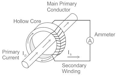
- The Current Transformer ( C.T. ), is a type of “instrument transformer” that is designed to produce an alternating current in its secondary winding which is proportional to the current being measured in its primary.
- The transformer's primary winding is physically connected in series with the conductor that carries the measured current flowing in the circuit.
- Generally, current transformers and ammeters are used together as a matched pair in which the design of the current transformer is such as to provide a maximum secondary current corresponding to a full-scale deflection on the ammeter.
- Current transformers “step-down” current levels from thousands of amperes down to standard output of a known ratio to either 5 Amps or 1 Amp for normal operation.
The ratio error in current transformer is attributed to:- a)Leakage flux
- b)magnetising component of no-load current
- c)power factor of the primary
- d)energy component of excitation current
Correct answer is option 'B'. Can you explain this answer?
The ratio error in current transformer is attributed to:
a)
Leakage flux
b)
magnetising component of no-load current
c)
power factor of the primary
d)
energy component of excitation current
| | Nishtha Chauhan answered |
The ratio error in a current transformer is primarily attributed to the magnetizing component of the no-load current. Let's understand the concept in detail:
1. Introduction:
A current transformer (CT) is an instrument transformer used to step down high currents to a safe and measurable level. It is widely employed in power systems for protection, metering, and control purposes. The accuracy of a current transformer is vital to ensure the reliability and safety of the electrical system.
2. Ratio Error:
Ratio error is the difference between the actual turns ratio of the current transformer and its rated turns ratio. It is expressed as a percentage and can be positive or negative. A perfect current transformer would have zero ratio error, meaning the secondary current would be an exact scaled-down replica of the primary current.
3. Magnetizing Component of No-Load Current:
When a current transformer is excited with a primary current, it draws a small amount of current from the supply, even when there is no secondary load connected. This is known as the no-load current. The no-load current consists of two components: the magnetizing component and the core loss component.
4. Magnetizing Component:
The magnetizing component of the no-load current is responsible for creating the magnetic flux required to transfer the primary current to the secondary winding. It is influenced by the magnetizing impedance of the current transformer.
5. Effect on Ratio Error:
The magnetizing component of the no-load current can cause a deviation in the turns ratio, resulting in a ratio error. This error occurs because the magnetizing impedance is not purely resistive but contains an inductive component. As a result, the voltage drop across the magnetizing impedance lags behind the applied voltage, leading to a phase shift.
6. Calculation of Ratio Error:
The ratio error can be calculated using the formula:
Ratio Error = (Measured Turns Ratio - Rated Turns Ratio) / Rated Turns Ratio * 100%
7. Minimizing Ratio Error:
To minimize the ratio error, current transformers are designed with low magnetizing impedance and high permeability cores. Additionally, the primary winding is usually wound with a large number of turns to reduce the effect of the magnetizing component.
In conclusion, the ratio error in a current transformer is primarily attributed to the magnetizing component of the no-load current. This component creates a phase shift and affects the turns ratio, leading to a deviation from the rated ratio. Minimizing the magnetizing impedance and optimizing the core design helps to reduce the ratio error and improve the accuracy of the current transformer.
The primary winding of a C.T. has _________- a)a larger number of turns
- b)no turns at all
- c)intermediate number of turns
- d)a few turns
Correct answer is option 'D'. Can you explain this answer?
The primary winding of a C.T. has _________
a)
a larger number of turns
b)
no turns at all
c)
intermediate number of turns
d)
a few turns
| | Pooja Patel answered |
The primary winding of a C.T. has a very few number of turns. It is connected in series with the load circuit through which the primary current flows.
What is the current transformer?- a)transformer used with an A.C. ammeter
- b)transformer used with an D.C. ammeter
- c)transformer used with an A.C. voltmeter
- d)transformer used with an D.C. voltmeter
Correct answer is option 'A'. Can you explain this answer?
What is the current transformer?
a)
transformer used with an A.C. ammeter
b)
transformer used with an D.C. ammeter
c)
transformer used with an A.C. voltmeter
d)
transformer used with an D.C. voltmeter
| | Pooja Patel answered |
A transformer used to extend the range of an A.C. ammeter is known as a current transformer. A current transformer is also abbreviated as C.T.
C.T. and P.T. are used for _________- a)measuring low current and voltages
- b)measuring very low current and voltages
- c)measuring high currentsand voltages
- d)measuring intermediate currents and voltages
Correct answer is option 'C'. Can you explain this answer?
C.T. and P.T. are used for _________
a)
measuring low current and voltages
b)
measuring very low current and voltages
c)
measuring high currentsand voltages
d)
measuring intermediate currents and voltages
| | Pooja Patel answered |
C.T. is basically used for the measurement of high currents. A P.T. is usually used for the measurement of high voltages. They are used with A.C. ammeters and voltmeters in order to extend their range.
A 110V voltmeter can measure a voltage of upto 110kV using a _________- a)110000/110V P.T.
- b)110000V P.T.
- c)110V P.T.
- d)110/110000V P.T.
Correct answer is option 'A'. Can you explain this answer?
A 110V voltmeter can measure a voltage of upto 110kV using a _________
a)
110000/110V P.T.
b)
110000V P.T.
c)
110V P.T.
d)
110/110000V P.T.
| | Pooja Patel answered |
An 110000/110V potential transformer can be used for measuring a voltage of upto 110000V by making use of a voltmeter with 110V voltage reading.
Up to a voltage of __________, Potential Transformers (PTs) are usually of dry type.- a)15000 V
- b)5000 V
- c)1000 V
- d)2000 V
Correct answer is option 'B'. Can you explain this answer?
Up to a voltage of __________, Potential Transformers (PTs) are usually of dry type.
a)
15000 V
b)
5000 V
c)
1000 V
d)
2000 V
| | Pooja Patel answered |
Potential transformer:
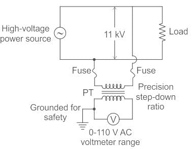
- The potential transformer is a voltage step-down transformer that reduces the voltage of a high voltage circuit to a lower level for the purpose of measurement.
- The primary winding consists of a large number of turns which is connected across the high voltage side or the line in which measurements have to be taken or to be protected.
- The secondary winding has a lesser number of turns which is connected to the voltmeters.
- The primaries of PT are rated from 400 V to several thousand volts and secondaries are always for 110 V.
- Up to voltages of 5,000, potential transformers are usually of the dry type.
- If the voltage is between 5,000 and 13,800 volts, then the transformer may be either dry type or oil-immersed type.
- For the voltages above 13,800 volts, they are always an oil-immersed type of transformer.
The primary of a _______ should never be energised when its secondary is open circuited.- a)Potential transformer
- b)Current transformer
- c)Autotransformer
- d)Power transformer
Correct answer is option 'B'. Can you explain this answer?
The primary of a _______ should never be energised when its secondary is open circuited.
a)
Potential transformer
b)
Current transformer
c)
Autotransformer
d)
Power transformer
| | Pooja Patel answered |
Current Transformer:
The secondary side of the current transformer is always kept short-circuited in order to avoid core saturation and high voltage induction so that the current transformer can be used to measure high values of currents.
The secondary side of the current transformer is always kept short-circuited in order to avoid core saturation and high voltage induction so that the current transformer can be used to measure high values of currents.
- The current transformer works on the principle of shorted secondary.
- It means that the burden on the system Zb is equal to 0.
- Thus, the current transformer produces a current in its secondary which is proportional to the current in its primary..
How can the meter circuit be isolated from the power circuit?- a)by grounding
- b)through electrical isolation
- c)by physical separation
- d)through mechanical isolation
Correct answer is option 'B'. Can you explain this answer?
How can the meter circuit be isolated from the power circuit?
a)
by grounding
b)
through electrical isolation
c)
by physical separation
d)
through mechanical isolation
| | Pooja Patel answered |
Leads of the secondary winding transformer are brought to the switch board thus separating them from high voltage windings. In this way, the meter circuit is isolated from the high voltage power circuit.
Chapter doubts & questions for Instrument Transformers - 3 Months Preparation for GATE Electrical 2026 is part of Electrical Engineering (EE) exam preparation. The chapters have been prepared according to the Electrical Engineering (EE) exam syllabus. The Chapter doubts & questions, notes, tests & MCQs are made for Electrical Engineering (EE) 2026 Exam. Find important definitions, questions, notes, meanings, examples, exercises, MCQs and online tests here.
Chapter doubts & questions of Instrument Transformers - 3 Months Preparation for GATE Electrical in English & Hindi are available as part of Electrical Engineering (EE) exam. Download more important topics, notes, lectures and mock test series for Electrical Engineering (EE) Exam by signing up for free.
3 Months Preparation for GATE Electrical676 videos|1399 docs|882 tests |