


All Exams > Electrical Engineering (EE) > 3 Months Preparation for GATE Electrical > All Questions
All questions of Electrical & Electronic Measurements for Electrical Engineering (EE) Exam
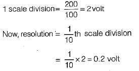
A moving coil voltmeter has a uniform scale with 100 divisions, the full scale reading is 200 V and 1/10 of a scale division can be estimated with a fair degree of certainty.The resolution of the instrument in volt is- a)2
- b)0.01
- c)0.2
- d)1
Correct answer is option 'C'. Can you explain this answer?
A moving coil voltmeter has a uniform scale with 100 divisions, the full scale reading is 200 V and 1/10 of a scale division can be estimated with a fair degree of certainty.The resolution of the instrument in volt is
a)
2
b)
0.01
c)
0.2
d)
1
| | Abhishek Chauhan answered |

A CRO can display:- a)D.C. signals only
- b)A.C. signals only
- c)Both D.C. and A.C. signals
- d)Time-invariant signals
Correct answer is option 'C'. Can you explain this answer?
A CRO can display:
a)
D.C. signals only
b)
A.C. signals only
c)
Both D.C. and A.C. signals
d)
Time-invariant signals
| | Pooja Patel answered |
- A Cathode Ray Oscilloscope is used for the measurement of AC as well as DC quantities
- It is used for the calculation of peak to peak voltage, RMS value, duty cycle etc
- CRO is a very useful and versatile laboratory instrument used for display, measurement and analysis of waveforms

Turns ration for a C.T. is _________- a)n = Np ⁄ Ns
- b)n = Ns ⁄ Np
- c)n = 1 ⁄ Np
- d)n = Ns
Correct answer is option 'B'. Can you explain this answer?
Turns ration for a C.T. is _________
a)
n = Np ⁄ Ns
b)
n = Ns ⁄ Np
c)
n = 1 ⁄ Np
d)
n = Ns
 | Pioneer Academy answered |
The turns ratio for a C.T. is defined as the ratio of the number of turns in the secondary to the number of turns in the primary. It is given by the relation

Loading effect in a voltmeter can be avoided by- a)using high voltage range
- b)using a high sensitive voltmeter
- c)using an accurate and precise instrument
- d)using a low sensitive voltmeter
Correct answer is option 'C'. Can you explain this answer?
Loading effect in a voltmeter can be avoided by
a)
using high voltage range
b)
using a high sensitive voltmeter
c)
using an accurate and precise instrument
d)
using a low sensitive voltmeter
| | Rhea Reddy answered |
Higher the sensitivity of the voltmeter, lower the loading effect and vice-versa.
An oscilloscope works similar to _______.- a)an ohmmeter
- b)a voltmeter
- c)an ammeter
- d)a multimeter
Correct answer is option 'B'. Can you explain this answer?
An oscilloscope works similar to _______.
a)
an ohmmeter
b)
a voltmeter
c)
an ammeter
d)
a multimeter
| | Gitanjali Deshpande answered |
An oscilloscope works similar to a voltmeter.
Explanation:
An oscilloscope is an electronic test instrument that is used to visualize and analyze the waveform of electrical signals. It displays the signal amplitude (voltage) on the vertical axis and the time on the horizontal axis. On the other hand, a voltmeter is a measuring instrument used to measure the voltage or potential difference between two points in an electrical circuit.
How does an oscilloscope work?
An oscilloscope works by capturing and displaying the voltage waveform of an electrical signal. It does this by using a cathode-ray tube (CRT) or a digital display. The oscilloscope's input is connected to the circuit under test, and it converts the electrical signal into a graphical representation on the display.
Similarities between an oscilloscope and a voltmeter:
1. Measure voltage: Both an oscilloscope and a voltmeter are used to measure voltage. While a voltmeter provides a numerical reading of the voltage, an oscilloscope visually displays the voltage waveform.
2. Accuracy: Both instruments can provide accurate voltage measurements. However, the accuracy of an oscilloscope may depend on factors such as the bandwidth and calibration.
3. Range: Both instruments have a range of voltage measurements. A voltmeter typically has multiple voltage ranges, allowing it to measure a wide variety of voltages. Similarly, an oscilloscope can be adjusted to display different voltage ranges.
4. Input impedance: Both instruments have a high input impedance, which means that they draw minimal current from the circuit under test. This allows them to measure voltage without significantly affecting the circuit's behavior.
5. Probing: Both instruments require a probe to connect to the circuit under test. The probe is connected to the instrument's input and allows for safe and accurate voltage measurements.
Differences between an oscilloscope and a voltmeter:
1. Function: While a voltmeter is primarily used to measure voltage, an oscilloscope can also display other characteristics of a signal, such as frequency, phase, and waveform distortion.
2. Visualization: An oscilloscope provides a visual representation of the voltage waveform, allowing for detailed analysis. In contrast, a voltmeter only provides a numerical reading of the voltage.
3. Time-domain analysis: An oscilloscope can capture and display the voltage waveform in the time domain, showing how the voltage changes over time. This is particularly useful for analyzing dynamic signals, such as audio or video signals. In contrast, a voltmeter typically provides a static voltage reading at a specific moment in time.
In conclusion, while a voltmeter provides a numerical measurement of voltage, an oscilloscope visually displays the voltage waveform. Both instruments are used to measure voltage, but an oscilloscope offers additional features for signal analysis and visualization.
Telephone companies make use of the Wheatstone bridge for _________.- a)measuring the telephone resistance
- b)computing the line strength
- c)maintaining Dialtone
- d)locating the cable faults
Correct answer is option 'D'. Can you explain this answer?
Telephone companies make use of the Wheatstone bridge for _________.
a)
measuring the telephone resistance
b)
computing the line strength
c)
maintaining Dialtone
d)
locating the cable faults
| | Sinjini Reddy answered |
Explanation:
Wheatstone Bridge:
- The Wheatstone bridge is a circuit used to measure an unknown electrical resistance by balancing two legs of a bridge circuit.
- It consists of four resistors, a voltage source, and a galvanometer.
Locating Cable Faults:
- Telephone companies use the Wheatstone bridge to locate faults in cables.
- When a fault occurs in a cable, it creates an imbalance in the resistance values in the circuit.
- By using the Wheatstone bridge, technicians can determine the exact location of the fault by measuring the resistance values on either side of the fault.
Working Principle:
- The Wheatstone bridge works on the principle of null detection, where the galvanometer reads zero when the bridge is balanced.
- If there is a fault in the cable, the resistance values change, causing the galvanometer to deflect from zero.
- By adjusting the known resistances in the bridge circuit, technicians can bring the bridge back into balance, indicating the location of the fault.
Benefits:
- Using the Wheatstone bridge for locating cable faults is a precise and efficient method.
- It helps in quickly identifying the exact location of the fault without the need for extensive manual testing.
- This method saves time and resources for telephone companies in maintaining and repairing their communication networks.
A voltmeter connected across 15 kΩ resistor reads 10 V in the circuit given. Voltmeter is rated at 500 Ω / volt and has a full- scale reading of 20 V. The supply voltage is:
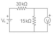
- a)60 V
- b)45 V
- c)30 V
- d)90 V
Correct answer is option 'A'. Can you explain this answer?
A voltmeter connected across 15 kΩ resistor reads 10 V in the circuit given. Voltmeter is rated at 500 Ω / volt and has a full- scale reading of 20 V. The supply voltage is:
a)
60 V
b)
45 V
c)
30 V
d)
90 V
 | Cstoppers Instructors answered |
Concept:
The voltmeter sensitivity (Sv) is determined by dividing the sum of the resistance of the meter (Rm)
Mathematically, sensitivity is expressed as:

E = Rated Voltage or Full scale Reading
Voltmeter sensitivity is expressed in Ohm/Volt
Rm = Sv × E
E = Rated Voltage or Full scale Reading
Voltmeter sensitivity is expressed in Ohm/Volt
Rm = Sv × E
Calculation:
Sensitivity of voltmeter = 500 Ω/V
Internal resistance of voltmeter = 500 ×
20 = 10 kΩ
Effective resistance across A – B is
= 10 || 15 = 6 kΩ
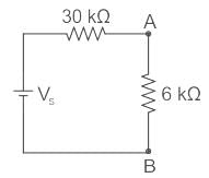
The voltmeter reading is 10 V
⇒ VAB = 10 V
By voltage division,
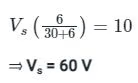
Sensitivity of voltmeter = 500 Ω/V
Internal resistance of voltmeter = 500 ×
20 = 10 kΩ
Effective resistance across A – B is
= 10 || 15 = 6 kΩ
The voltmeter reading is 10 V
⇒ VAB = 10 V
By voltage division,
Phantom leading for testing of energy meter is used- a)for meters having fow current ratings.
- b)to reduce power loss during testing.
- c)to isolate the current and potential circuits.
- d)to test meters having a large current ratings for which loads may not be available in the laboratory. This also reduce power losses during testing.
Correct answer is option 'D'. Can you explain this answer?
Phantom leading for testing of energy meter is used
a)
for meters having fow current ratings.
b)
to reduce power loss during testing.
c)
to isolate the current and potential circuits.
d)
to test meters having a large current ratings for which loads may not be available in the laboratory. This also reduce power losses during testing.
| | Sharmila Kulkarni answered |
When the energy meter is tested under high current rating, there is lot of waste of power. To reduce this unwanted power loss, Phantom or Fictitious loading is done.
Two resistors R1, and R2 are connected in series with R1 = 28.7 Ω and R2 = 3.624 Ω. The total resistance to the appropriate number of significant figures can be written as- a)32.324Ω
- b)32.4Ω
- c)32.32 Ω
- d)32.3Ω
Correct answer is option 'D'. Can you explain this answer?
Two resistors R1, and R2 are connected in series with R1 = 28.7 Ω and R2 = 3.624 Ω. The total resistance to the appropriate number of significant figures can be written as
a)
32.324Ω
b)
32.4Ω
c)
32.32 Ω
d)
32.3Ω
| | Anuj Rane answered |
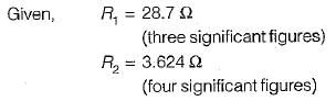
For series connection,
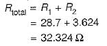
Since one of the resistance (i.e. R1) is accurate only to three significant figures, therefore the result of R total has to be reduced to three significant figures. Hence, total resistance
By using the variations on a Wheatstone bridge we can _________.- a)measure quantities such as voltage, current, and power
- b)measure high resistance values
- c)measure quantities such as complex power
- d)measure quantities such as capacitance, inductance, and impedance
Correct answer is option 'D'. Can you explain this answer?
By using the variations on a Wheatstone bridge we can _________.
a)
measure quantities such as voltage, current, and power
b)
measure high resistance values
c)
measure quantities such as complex power
d)
measure quantities such as capacitance, inductance, and impedance
| | Sarita Yadav answered |
In its simplest form, a Whetstone bridge consists of resistive arms. A Wheatstone bridge is used to measure quantities such as capacitance, inductance, and impedance by using the variations.
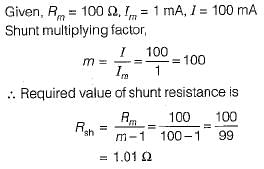
Which of the following is not a desired characteristic of shunts used in PMMC instruments?- a)The resistance of the shunt should not vary with time.
- b)It must be manufactured using manganin or copper.
- c)It should have a low thermal emf.
- d)It should carry the current without excessive temperature rise.
Correct answer is option 'B'. Can you explain this answer?
Which of the following is not a desired characteristic of shunts used in PMMC instruments?
a)
The resistance of the shunt should not vary with time.
b)
It must be manufactured using manganin or copper.
c)
It should have a low thermal emf.
d)
It should carry the current without excessive temperature rise.
| | Sakshi Roy answered |
Shunts used in PMMC instruments are made up of manganin or constantan since they have very low temperature coefficient of resistance.
The declared constant of a 5 A, 220 V d.c. watthour meter is 3275 revolutions per kWh. The speed of the disc at full load is- a)8 rps
- b)3 rps
- c)1 rps
- d)2 rps
Correct answer is option 'C'. Can you explain this answer?
The declared constant of a 5 A, 220 V d.c. watthour meter is 3275 revolutions per kWh. The speed of the disc at full load is
a)
8 rps
b)
3 rps
c)
1 rps
d)
2 rps
| | Preethi Banerjee answered |
Here, cos φ = 1 (for d.c. watthour meter) Energy supplied to the energy meter in kWh
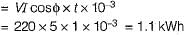
∴ Energy supplied to the energy meter per minute =
Given, energy meter constant, K = 3275 revolutions/kWh
∴ Disc speed in rpm = Energy supplied per minute x Energy meter constant

∴ Energy supplied to the energy meter per minute =
Given, energy meter constant, K = 3275 revolutions/kWh
∴ Disc speed in rpm = Energy supplied per minute x Energy meter constant
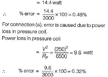
A wattmeter has a current coil of 0.1 Ω resistance and a pressure coil of 6500 Ω respectively. The wattmeter shows a reading of 12 A at 250 V with unity power factor. The percentage errors, due to resistance only with each of the two methods of connections shown below will be respectively- a)0.26% in connection (i) and 0.16% in connection (ii)
- b)0.32% in connection (i) and 0.48% in connection (ii)
- c)0.16% in connection (i) and 0.26% in connection (ii)
- d)0.48% in connection (i) and 0.32% in connection (a)
Correct answer is option 'D'. Can you explain this answer?
A wattmeter has a current coil of 0.1 Ω resistance and a pressure coil of 6500 Ω respectively. The wattmeter shows a reading of 12 A at 250 V with unity power factor. The percentage errors, due to resistance only with each of the two methods of connections shown below will be respectively
a)
0.26% in connection (i) and 0.16% in connection (ii)
b)
0.32% in connection (i) and 0.48% in connection (ii)
c)
0.16% in connection (i) and 0.26% in connection (ii)
d)
0.48% in connection (i) and 0.32% in connection (a)
| | Dipika Basak answered |

A bridge circuit works at a frequency of 3 kHz. Which detector can be used for detecting the null conditions in the bridge?- a)Vibration galvanometer and tunable amplifiers.
- b)Vibration galvanometer and head phones.
- c)Headphones and tunable amplifiers.
- d)Vibration galvanometer, headphones and tunable amplifiers.
Correct answer is option 'C'. Can you explain this answer?
A bridge circuit works at a frequency of 3 kHz. Which detector can be used for detecting the null conditions in the bridge?
a)
Vibration galvanometer and tunable amplifiers.
b)
Vibration galvanometer and head phones.
c)
Headphones and tunable amplifiers.
d)
Vibration galvanometer, headphones and tunable amplifiers.
| | Nikhil Iyer answered |
For 3 kHz frequency headphone (Range - 250 Hz to 4 kHz) and tuned amplifier detector (Range - 10 Hz to 100 kHz) will be used.
In measurement of resistance by “Carey Foster bridge” no error is introduced due to- a)connecting leads
- b)thermoelectric emfs
- c)contact resistance
- d)ail of the above
Correct answer is option 'D'. Can you explain this answer?
In measurement of resistance by “Carey Foster bridge” no error is introduced due to
a)
connecting leads
b)
thermoelectric emfs
c)
contact resistance
d)
ail of the above
| | Raj Choudhary answered |
“Carey Foster slide wire bridge” is a special type of bridge circuit which is used for the measurement of medium resistance by comparing with a standard known resistance. This bridge circuit will give no error due to connecting lead resistances, thermoelectric emfs and contact resistances.
A PMMC uses a :- a)taut bond
- b)moving coil
- c)electrodynamometer
- d)moving iron type
Correct answer is option 'B'. Can you explain this answer?
A PMMC uses a :
a)
taut bond
b)
moving coil
c)
electrodynamometer
d)
moving iron type
| | Siddharth Khanna answered |
A PMMC uses a moving coil and the magnet is permanent.
The arm consisting of the standard known resistance R3 is known as __________.- a)standard arm
- b)resistance arm
- c)accurate arm
- d)known arm
Correct answer is option 'A'. Can you explain this answer?
The arm consisting of the standard known resistance R3 is known as __________.
a)
standard arm
b)
resistance arm
c)
accurate arm
d)
known arm
| | Sanvi Kapoor answered |
The arm consisting of the standard known resistance R3 is known as the legal arm. Using this resistance value, the unknown resistance can be determined using the balance condition.
The braking torque provided by a permanent magnet in a single phase meter is proportional to the- a)square of the flux of the permanent magnet
- b)speed of the meter
- c)both (a) and (b)
- d)neither (a) nor (b)
Correct answer is option 'C'. Can you explain this answer?
The braking torque provided by a permanent magnet in a single phase meter is proportional to the
a)
square of the flux of the permanent magnet
b)
speed of the meter
c)
both (a) and (b)
d)
neither (a) nor (b)
| | Gargi Basak answered |
Braking torque provided by the permanent magnet is given by

Where,
N = speed of the disc in rpm
φm = maximum value of flux of the permanent magnet
d = distance of the permanent magnet from the centre of the revolving disc
Where,
N = speed of the disc in rpm
φm = maximum value of flux of the permanent magnet
d = distance of the permanent magnet from the centre of the revolving disc
The condition for a resistor to have the same value of resistance at medium frequencies as with d.c. is- a)CR2 = ωL
- b)CR2 = 2L
- c)CR2 = L
- d)CR2 = 2 ωL
Correct answer is option 'B'. Can you explain this answer?
The condition for a resistor to have the same value of resistance at medium frequencies as with d.c. is
a)
CR2 = ωL
b)
CR2 = 2L
c)
CR2 = L
d)
CR2 = 2 ωL
| | Rahul Banerjee answered |
At high and medium frequencies, a resistor can be represented as shown in figure below.
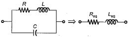
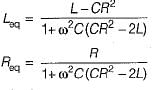
The equivalent impedance of the above shown resistor at an angular frequency ω rad/s is
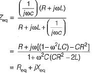
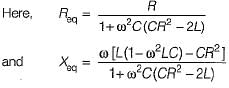
If the resistance is to remain independent of frequency i.e. to have the same value of resistance at medium frequencies as with d.c, we have:
CR2 = 2 L
so that, Req = R
The equivalent impedance of the above shown resistor at an angular frequency ω rad/s is
If the resistance is to remain independent of frequency i.e. to have the same value of resistance at medium frequencies as with d.c, we have:
CR2 = 2 L
so that, Req = R
The below symbol which is used in single line diagrams represents ________
- a)current transformer
- b)circuit breaker
- c)potential transformer
- d)power transformer
Correct answer is option 'C'. Can you explain this answer?
The below symbol which is used in single line diagrams represents ________
a)
current transformer
b)
circuit breaker
c)
potential transformer
d)
power transformer
| | Pooja Patel answered |
The symbols of different equipment used in single line diagram are shown below.
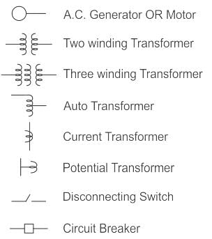
Hence, the given symbol is for the potential transformer.
Under operating conditions, the secondary of a current transformer is always short-circuited because of ________.- a)It protects the primary circuits
- b)It is safe to human beings
- c)It avoids core saturation and high voltage induction
- d)None of these
Correct answer is option 'C'. Can you explain this answer?
Under operating conditions, the secondary of a current transformer is always short-circuited because of ________.
a)
It protects the primary circuits
b)
It is safe to human beings
c)
It avoids core saturation and high voltage induction
d)
None of these
| | Prasad Verma answered |
Understanding Current Transformers
Current transformers (CTs) are essential components in electrical engineering, used to measure alternating current (AC). They work by producing a reduced current that is proportional to the current flowing in the primary circuit.
Importance of Short-Circuiting the Secondary
When operating a current transformer, the secondary side is always short-circuited for several critical reasons:
Core Saturation Prevention
- Avoiding Core Saturation: If the secondary winding is open-circuited, the current transformer will not have a proper path for the current to flow. This can lead to excessive magnetic flux in the core, causing it to saturate. A saturated core cannot accurately transform the primary current, leading to measurement errors.
High Voltage Induction Prevention
- High Voltage Risks: An open secondary can result in very high voltages being induced in the secondary winding due to the lack of load. This high voltage can be dangerous, potentially damaging the CT and creating safety hazards.
Protection of Primary Circuits
- Protection Mechanism: Short-circuiting the secondary ensures that the primary circuit remains protected from high voltage, which could occur if the secondary is left open.
Safety Considerations
- Safety for Human Beings: While short-circuiting the secondary does enhance safety by preventing high voltage, it primarily serves to protect the CT and maintain accurate measurements.
In summary, short-circuiting the secondary of a current transformer is crucial to avoid core saturation and high voltage induction, ensuring accurate current measurement and protecting both the device and the electrical system.
In order to reduce skin effect in resistance standards when they are used on high frequency a.c.- a)adjacent turns of the resistance coil should carry current in the opposite direction
- b)they should be provided with four terminals
- c)the diameter of the resistance wire should be small
- d)none of the above
Correct answer is option 'C'. Can you explain this answer?
In order to reduce skin effect in resistance standards when they are used on high frequency a.c.
a)
adjacent turns of the resistance coil should carry current in the opposite direction
b)
they should be provided with four terminals
c)
the diameter of the resistance wire should be small
d)
none of the above
| | Saumya Basak answered |
- To reduce the error in standard resistance due to stray inductance, the adjacent wires should carry current in opposite direction so as to reduce the resultant magnetic field.
- To reduce the error due to contact (lead) resistance, a four terminal construction is used.
- To reduce the skin effect when used at high frequency a.c., small diameter wires are used.
D.C. bridges are used for _________.- a)measurement of resistance
- b)measurement of capacitance
- c)measurement of current
- d)measurement of inductance
Correct answer is option 'A'. Can you explain this answer?
D.C. bridges are used for _________.
a)
measurement of resistance
b)
measurement of capacitance
c)
measurement of current
d)
measurement of inductance
| | Sarita Yadav answered |
Resistance measurements are done using a suitable D.C. bridge.
The arms consisting of the resistances R1 and R2 are called _________.- a)resistance arms
- b)impedance arms
- c)source arms
- d)ratio arms
Correct answer is option 'D'. Can you explain this answer?
The arms consisting of the resistances R1 and R2 are called _________.
a)
resistance arms
b)
impedance arms
c)
source arms
d)
ratio arms
| | Kabir Verma answered |
The arms consisting of the two resistances R1 and R2, are known as the resistance arms. Sources do not appear on the arms of the bridge, and they are connected across opposite ends. Wheatstone bridge is purely resistive.
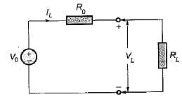
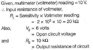
A multimeter having a sensitivity of 2 kΩ/V is used for the measurement of voltage across a circuit having an output resistance of 10 kΩ. The open circuit voltage of the circuit is 6 volts. The percentage error in multimeter reading when it is set to 10 volt is given by- a)33% low
- b)22% high
- c)33% high
- d)22% low
Correct answer is option 'A'. Can you explain this answer?
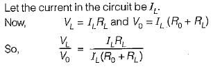
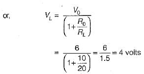
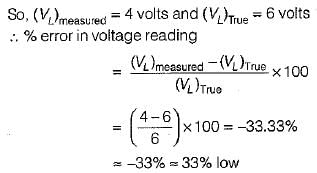
A multimeter having a sensitivity of 2 kΩ/V is used for the measurement of voltage across a circuit having an output resistance of 10 kΩ. The open circuit voltage of the circuit is 6 volts. The percentage error in multimeter reading when it is set to 10 volt is given by
a)
33% low
b)
22% high
c)
33% high
d)
22% low
| | Bijoy Mehta answered |
The circuit diagram for the measurement of voltage using multimeter is shown below:
A 5A ammeter can measure a current of upto 1000 A using a _________- a)5/1000A C.T.
- b)1000A C.T.
- c)5A C.T.
- d)1000/5A C.T.
Correct answer is option 'D'. Can you explain this answer?
A 5A ammeter can measure a current of upto 1000 A using a _________
a)
5/1000A C.T.
b)
1000A C.T.
c)
5A C.T.
d)
1000/5A C.T.
| | Pooja Patel answered |
A 1000/5A current transformer can be used for measuring a current of upto 1000A by making use of an ammeter with 5A current reading.
C.T. and P.T. are standardized at _________- a)50 A and 220 V
- b)25 mA and 2.2 kV
- c)5 A and 110 V
- d)75 nA and 1.1 MV
Correct answer is option 'C'. Can you explain this answer?
C.T. and P.T. are standardized at _________
a)
50 A and 220 V
b)
25 mA and 2.2 kV
c)
5 A and 110 V
d)
75 nA and 1.1 MV
| | Palak Verma answered |
The correct answer for the standardized values of C.T. (Current Transformer) and P.T. (Potential Transformer) is option 'C', which is 5 A and 110 V.
**Explanation:**
**Current Transformer (C.T.):**
- A Current Transformer is a type of instrument transformer used to measure alternating current (AC) in high voltage power systems.
- It steps down the high current flowing through the primary winding to a lower value suitable for measurement by instruments or protection relays.
- The secondary current of a C.T. is standardized at a particular value to ensure accuracy and compatibility with other devices in the power system.
- The standardized current rating for C.T. is typically 5 A for most applications.
- This means that when 5 A flows through the primary winding of the C.T., a proportional current of 5 A is obtained at the secondary winding.
**Potential Transformer (P.T.):**
- A Potential Transformer is another type of instrument transformer used to measure voltage in high voltage power systems.
- It steps down the high voltage to a lower value suitable for measurement by instruments or protection relays.
- The secondary voltage of a P.T. is standardized at a particular value to ensure accuracy and compatibility with other devices in the power system.
- The standardized voltage rating for P.T. is typically 110 V for most applications.
- This means that when 110 V is applied to the primary winding of the P.T., a proportional voltage of 110 V is obtained at the secondary winding.
**Why option 'C' is the correct answer:**
- Option 'C' states that C.T. and P.T. are standardized at 5 A and 110 V, respectively.
- This matches the standardized values commonly used for C.T.s and P.T.s in electrical power systems.
- The other options do not match the commonly standardized values and hence are incorrect.
- For example, option 'A' suggests that C.T. is standardized at 50 A, which is not a commonly used value.
- Similarly, option 'B' suggests that P.T. is standardized at 2.2 kV, which is also not a commonly used value.
- Option 'D' suggests extremely low current and extremely high voltage values, which are not practical for C.T.s and P.T.s in power systems.
Therefore, the correct answer is option 'C', which states that C.T. and P.T. are standardized at 5 A and 110 V, respectively.
A current transformer has double turn primary and a 100 turn secondary winding. The secondary draws current of 6 A and magnetising ampere-turns is 60 A. What is actual transformation ratio?- a)100.5
- b)101
- c)50.24
- d)25.12
Correct answer is option 'C'. Can you explain this answer?
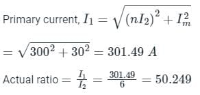
A current transformer has double turn primary and a 100 turn secondary winding. The secondary draws current of 6 A and magnetising ampere-turns is 60 A. What is actual transformation ratio?
a)
100.5
b)
101
c)
50.24
d)
25.12
| | Pooja Patel answered |
Magnetizing ampere-turns = 60 A = NI
Magnetizing current (Im) = 30 A
Number of primary turns (N1) = 2
Number of secondary turns (N2) = 100

Magnetizing current (Im) = 30 A
Number of primary turns (N1) = 2
Number of secondary turns (N2) = 100
Exciting current (I0) = Im = 30 A
The rated secondary current (I2) = 6 A
Reflected secondary current = nI2 = 50 x 6 = 300 A
Resistance R4 is known as ________.- a)standard resistance
- b)unknown resistance to be measured
- c)resistance arm
- d)input resistance
Correct answer is option 'B'. Can you explain this answer?
Resistance R4 is known as ________.
a)
standard resistance
b)
unknown resistance to be measured
c)
resistance arm
d)
input resistance
| | Kabir Verma answered |
R4 is the unknown resistance whose value has to be found by comparison with a standard. R3 is known as the standard resistance. The resistance arm comprises four resistances, including R1, R2, R3, and R4.
Which one of the following meters is an induction type instrument?- a)Ammeter
- b)Voltmeter
- c)Energymeter
- d)Multimeter
Correct answer is option 'C'. Can you explain this answer?
Which one of the following meters is an induction type instrument?
a)
Ammeter
b)
Voltmeter
c)
Energymeter
d)
Multimeter
| | Saumya Basak answered |
An energymeter is an induction and an integrating type instrument.
The primary winding of a P.T. has _________- a)intermediate number of turns
- b)no turns at all
- c)a larger number of turns
- d)a few turns
Correct answer is option 'C'. Can you explain this answer?
The primary winding of a P.T. has _________
a)
intermediate number of turns
b)
no turns at all
c)
a larger number of turns
d)
a few turns
| | Pooja Patel answered |
The primary winding of a P.T. has a very large number of turns. It is connected in parallel with the load whose voltage is to be measured.
In a dual slope integrating type DVM, the accuracy of measured voltage ________ on the integrating time constant and ______ of frequency of oscillation.- a)depends, independent
- b)doesn't depend, function
- c)doesn't depend, independent
- d)depends, function
Correct answer is option 'C'. Can you explain this answer?
In a dual slope integrating type DVM, the accuracy of measured voltage ________ on the integrating time constant and ______ of frequency of oscillation.
a)
depends, independent
b)
doesn't depend, function
c)
doesn't depend, independent
d)
depends, function
| | Pooja Patel answered |
Dual slope integrating type is the popular method of Analog to Digital conversion. In dual slope method, the noise is averaged out by the positive and negative ramps using the process of integration.
The basic principle of this method is that the input signal is integrated for a fixed interval of time and then same integrator is used to integrate the reference voltage with reverse slope.
Hence the name is given to the technique is dual slope integration technique.
Dual slope integrating type ADC is the most accurate type of ADC because of non-dependency on variation in components values caused by noise.
These reduce design complexity and improves measurement quality.
The accuracy of the measured voltage is independent of the integrator time constant and the accuracy of the method is also independent of the oscillator frequency.
Instrument transformers provide _________- a)electrical isolation from low rated winding
- b)electrical isolation from high rated winding
- c)electrical isolation from medium rated winding
- d)no electrical isolation at all
Correct answer is option 'B'. Can you explain this answer?
Instrument transformers provide _________
a)
electrical isolation from low rated winding
b)
electrical isolation from high rated winding
c)
electrical isolation from medium rated winding
d)
no electrical isolation at all
| | Niharika Basu answered |
Electrical Isolation from High Rated Winding:
Instrument transformers provide electrical isolation from high rated winding. This means that the primary winding (high voltage side) is physically separated from the secondary winding (low voltage side) in the instrument transformer. This isolation helps prevent any potential electrical hazards and ensures the safety of the equipment and personnel.
Importance of Electrical Isolation:
- Protects equipment: By isolating the high voltage side from the low voltage side, instrument transformers help prevent damage to sensitive equipment that may not be designed to handle high voltages.
- Prevents electrical shock: Electrical isolation reduces the risk of electric shock to personnel working with the equipment, as it creates a physical barrier between high and low voltage components.
- Ensures accuracy: Isolating the windings helps maintain the accuracy of the measurements taken by the instrument transformer, as there is no interference from the high voltage side.
- Compliance with regulations: Electrical isolation is often a requirement in electrical systems to comply with safety standards and regulations.
Types of Instrument Transformers:
- Current transformers (CTs): Used to measure alternating current (AC) on high voltage circuits. They provide a scaled-down current in the secondary winding for measurement and protection purposes.
- Voltage transformers (VTs) or potential transformers (PTs): Used to step down high voltage for measurement and protection. They provide a scaled-down voltage in the secondary winding.
Conclusion:
Instrument transformers play a crucial role in electrical systems by providing electrical isolation from high rated windings. This isolation ensures safety, accuracy, and compliance with regulations in various applications, making instrument transformers essential components in power systems.
In an induction type energy meter, an increase in temperature results in- a)a decrease in torque produced by all shading bands.
- b)a decrease in the resistance of the eddy current paths,
- c)an increase in the angle of lag ‘α’ of the eddy currents,
- d)an increase in angle of lag between V and potential coil flux φp.
Correct answer is option 'A'. Can you explain this answer?
In an induction type energy meter, an increase in temperature results in
a)
a decrease in torque produced by all shading bands.
b)
a decrease in the resistance of the eddy current paths,
c)
an increase in the angle of lag ‘α’ of the eddy currents,
d)
an increase in angle of lag between V and potential coil flux φp.
| | Janhavi Roy answered |
An increase in temperature is accompanied by a rise in resistance of ail copper and aluminium parts.
A current carrying conductor is wrapped eight times around the jaw of a clamp-on meter that reads 50 A. What will be the actual value of the conductor current?- a)400 A
- b)6.25 A
- c)50 A
- d)12.5 A
Correct answer is option 'B'. Can you explain this answer?
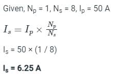
A current carrying conductor is wrapped eight times around the jaw of a clamp-on meter that reads 50 A. What will be the actual value of the conductor current?
a)
400 A
b)
6.25 A
c)
50 A
d)
12.5 A
| | Pooja Patel answered |
Concept:
Current transformer:
- A current transformer is a device that is used to measure high alternating current in a conductor.
- In the figure shown below the conductor act as the primary winding of a single turn that passed through the circular laminated iron core.
- The secondary winding consists of a large number of turns of fine wire wrapped around the core.
- Due to transformer action, the secondary current transforms into a lower value.
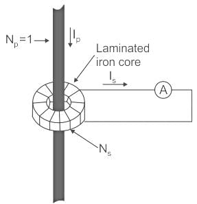
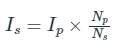
Let, Np is a number of turn in the primary winding
Ns is the number of turns in the secondary winding.
Ip and Is are primary and secondary turns respectively.
Therefore, the secondary current is given by,
Ns is the number of turns in the secondary winding.
Ip and Is are primary and secondary turns respectively.
Therefore, the secondary current is given by,
- Therefore, the current transformer changes the current into a lower value that can easily be measured by the measuring instrument.
- Along with a Potential transformer (PT), a current transformer (CT) can measure Power and energy also.
- Hence, CT used with Ammeter, Wattmeter, and Watt-hour meter.
Calculation:
Assertion (A): An electrodynamometer type wattmeter reads low when the load power factor is leading.
Reason (R): The effect of pressure coil inductance is to increase the phase angle between load current and pressure coil current when the load power factor is leading.- a)Both A and R are true and R is a correct explanation of A.
- b)Both A and R are true but R is not a correct explanation of A.
- c)A is true but R is false.
- d)A is false but R is true.
Correct answer is option 'A'. Can you explain this answer?
Assertion (A): An electrodynamometer type wattmeter reads low when the load power factor is leading.
Reason (R): The effect of pressure coil inductance is to increase the phase angle between load current and pressure coil current when the load power factor is leading.
Reason (R): The effect of pressure coil inductance is to increase the phase angle between load current and pressure coil current when the load power factor is leading.
a)
Both A and R are true and R is a correct explanation of A.
b)
Both A and R are true but R is not a correct explanation of A.
c)
A is true but R is false.
d)
A is false but R is true.
| | Anirban Gupta answered |
Assertion (A): An electrodynamometer type wattmeter reads low when the load power factor is leading.
Reason (R): The effect of pressure coil inductance is to increase the phase angle between load current and pressure coil current when the load power factor is leading.
Explanation:
A is true because an electrodynamometer type wattmeter is designed to measure the real power in a circuit. In a circuit with a leading power factor, the wattmeter will read low due to the effect of inductive reactance in the pressure coil.
R is a correct explanation of A because when the load power factor is leading, there is a phase difference between the current flowing through the load and the current flowing through the pressure coil of the wattmeter. The inductance of the pressure coil causes a lagging current, which increases the phase angle between the load current and the pressure coil current. This leads to an error in the measurement of real power by the wattmeter.
To understand this concept more clearly, let's break down the explanation into key points:
1. Electrodynamometer Type Wattmeter:
- An electrodynamometer type wattmeter is a type of instrument used to measure the real power in a circuit.
- It works on the principle of the interaction between the magnetic field produced by the current in the pressure coil and the magnetic field produced by the current in the current coil.
2. Leading Power Factor:
- In a circuit with a leading power factor, the current leads the voltage waveform.
- This means that the current waveform reaches its peak before the voltage waveform.
3. Effect of Pressure Coil Inductance:
- The pressure coil of the electrodynamometer type wattmeter has inductance due to the presence of a coil.
- Inductance causes a phase lag between the current and voltage waveforms.
- When the load power factor is leading, the phase angle between the load current and the pressure coil current increases.
- This increased phase angle causes the wattmeter to read low.
Conclusion:
Both Assertion (A) and Reason (R) are true, and Reason (R) is a correct explanation of Assertion (A). The effect of pressure coil inductance is to increase the phase angle between load current and pressure coil current when the load power factor is leading, leading to a low reading on the electrodynamometer type wattmeter.
Multiplication features are incorporated in an ohmmeter to enable the meter to ________.- a)measure very high resistance values
- b)measure values with the least error
- c)be multipurpose in its application
- d)has less power consumption
Correct answer is option 'B'. Can you explain this answer?
Multiplication features are incorporated in an ohmmeter to enable the meter to ________.
a)
measure very high resistance values
b)
measure values with the least error
c)
be multipurpose in its application
d)
has less power consumption
| | Pooja Patel answered |
To enable the ohmmeter to indicate any value being measured, with the least error, scale multiplication features are used in most ohmmeters.
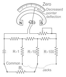
- A typical meter will have four test lead jacks: COMMON, R X 1, R X 10, and R X 100
- The jack marked COMMON is connected internally through the battery to one side of the moving coil of the ohmmeter
- The jacks marked R X 1, R X 10, and R X 100 are connected to three different size resistors located within the ohmmeter
What is the value of multiplier resistance on the 50 V range of a dc voltmeter that uses a 500 μA meter movement with an internal resistance of 1 kΩ?- a)109 kΩ
- b)199 kΩ
- c)99 kΩ
- d)119 kΩ
Correct answer is option 'C'. Can you explain this answer?
What is the value of multiplier resistance on the 50 V range of a dc voltmeter that uses a 500 μA meter movement with an internal resistance of 1 kΩ?
a)
109 kΩ
b)
199 kΩ
c)
99 kΩ
d)
119 kΩ
| | Lakshmi Desai answered |
The sensitivity of 500 μA meter movement is given by,
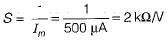
The value of the multiplier resistance can be obtained as
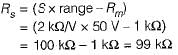
The value of the multiplier resistance can be obtained as
A dynamometer wattmeter with its voltage coil connected across the load side of the instrument reads 250 W, If the load voltage be 200 V, what power is being taken by the load?
(The voltage coil has a resistance of 2000 Ω)- a)250 W
- b)270 W
- c)230 W
- d)can’t be determined
Correct answer is option 'C'. Can you explain this answer?
A dynamometer wattmeter with its voltage coil connected across the load side of the instrument reads 250 W, If the load voltage be 200 V, what power is being taken by the load?
(The voltage coil has a resistance of 2000 Ω)
(The voltage coil has a resistance of 2000 Ω)
a)
250 W
b)
270 W
c)
230 W
d)
can’t be determined
| | Prisha Kulkarni answered |
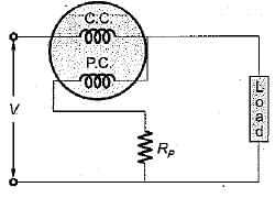
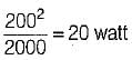
Power loss in the voltage coil =
instrument reading = 250 watt
∴ Actual load = 250 - 20
= 230 watt
A resistor R has an effective inductance of L and a distributed capacitance of C. its time constant at medium frequencies is- a)L/R - CR
- b)L/R
- c)CR
- d)CR - L/R
Correct answer is option 'A'. Can you explain this answer?
A resistor R has an effective inductance of L and a distributed capacitance of C. its time constant at medium frequencies is
a)
L/R - CR
b)
L/R
c)
CR
d)
CR - L/R
| | Debanshi Nair answered |
At medium frequencies, we have:
∴ Time constant,
∴ Time constant,
Wheatstone bridge is used to measure the d.c. resistance of various types of wires for _________.- a)determining their effective resistance
- b)computing the power dissipation
- c)quality control of wire
- d)maintaining a source of constant e.m.f
Correct answer is option 'C'. Can you explain this answer?
Wheatstone bridge is used to measure the d.c. resistance of various types of wires for _________.
a)
determining their effective resistance
b)
computing the power dissipation
c)
quality control of wire
d)
maintaining a source of constant e.m.f
| | Avinash Sharma answered |
Wheatstone bridge is used to measure the d.c. resistance of various types of wires for controlling the quality of the cables. The voltage source maintains a constant e.m.f in the bridge circuit.
A dynamometer wattmeter measures power in a 50 Hz, single phase circuit without error, at all power factors. The resistance of the voltage coil and its series resistance are 400 Ω and 10,000 Ω, respectively. The series resistance has a distributed self-capacitance equivalent to a shunt capacity of 20 pF.What is the self inductance of the pressure coil?- a)5 mH
- b)4 mH
- c)3 mH
- d)2 mH
Correct answer is option 'D'. Can you explain this answer?
A dynamometer wattmeter measures power in a 50 Hz, single phase circuit without error, at all power factors. The resistance of the voltage coil and its series resistance are 400 Ω and 10,000 Ω, respectively. The series resistance has a distributed self-capacitance equivalent to a shunt capacity of 20 pF.What is the self inductance of the pressure coil?
a)
5 mH
b)
4 mH
c)
3 mH
d)
2 mH
| | Swati Tiwari answered |
Given, Rp = 400Ω,
RS = 10,000 Ω
CC = 20 pF
Self inductance of the pressure coil is given by
Lp = CC x RS2
= 20 x 10-12 x (104)2
= 20 x 10-4 = 2 mH
RS = 10,000 Ω
CC = 20 pF
Self inductance of the pressure coil is given by
Lp = CC x RS2
= 20 x 10-12 x (104)2
= 20 x 10-4 = 2 mH
The secondary winding of a C.T. has _________- a)a large number of turns
- b)a few turns
- c)no turns at all
- d)intermediate number of turns
Correct answer is option 'A'. Can you explain this answer?
The secondary winding of a C.T. has _________
a)
a large number of turns
b)
a few turns
c)
no turns at all
d)
intermediate number of turns
| | Pooja Patel answered |
Secondary winding of a C.T. has a large number of turns. It is connected in series to an ammeter through which a small portion of the current flows through.
Which of the following is an advantage of the analog multimeter over the digital multimeter?- a)No loading effect
- b)High accuracy
- c)Smaller size
- d)Less electric noise
Correct answer is option 'D'. Can you explain this answer?
Which of the following is an advantage of the analog multimeter over the digital multimeter?
a)
No loading effect
b)
High accuracy
c)
Smaller size
d)
Less electric noise
| | Pooja Patel answered |
Digital multimeters have the following advantages over analog multimeters:
- More accurate
- Reduced reading and interpolation errors
- Parallax error is eliminated
- Faster and do not require zero adjustment
- Smaller size therefore portable
However, analog meters have some advantages over digital multimeters, cheaper and less electric noise.
The secondary winding of a P.T. has _________- a)a large number of turns
- b)intermediate number of turns
- c)no turns at all
- d)a few turns
Correct answer is option 'D'. Can you explain this answer?
The secondary winding of a P.T. has _________
a)
a large number of turns
b)
intermediate number of turns
c)
no turns at all
d)
a few turns
| | Pooja Patel answered |
Secondary winding of a P.T. has a few number of turns. A low range voltmeter is connected in parallel with the secondary winding.
Assertion (A): Gravity control is not suited for indicating instruments in general and portable instruments in particular.
Reason (R): Gravity control is used in only vertically mounted instruments.- a)Both A and R are true and R is a correct explanation of A.
- b)Both A and R are true but R is not a correct explanation of A.
- c)A is true but R is false.
- d)A is false but R is true.
Correct answer is option 'B'. Can you explain this answer?
Assertion (A): Gravity control is not suited for indicating instruments in general and portable instruments in particular.
Reason (R): Gravity control is used in only vertically mounted instruments.
Reason (R): Gravity control is used in only vertically mounted instruments.
a)
Both A and R are true and R is a correct explanation of A.
b)
Both A and R are true but R is not a correct explanation of A.
c)
A is true but R is false.
d)
A is false but R is true.
| | Tanishq Majumdar answered |
Gravity control is not suited for indicating instruments in general and portable instruments in particular because for using this type of control, the instruments must be mounted in level position otherwise there will be a very serious zero error. Gravity control is used in only vertically mounted instruments. Hence, reason is also a true statement but, not a correct explanation of assertion.
Two-wattmeter method is employed to measure power in a 3-phase balanced system with the current coils connected in the A and C lines. The phase sequence is ABC. If the wattmeter with its current coil in A-phase line reads zero, then the power factor of the 3-phase load will be- a)zero lagging
- b)zero leading
- c)0.5 lagging
- d)0.5 leading
Correct answer is option 'C'. Can you explain this answer?
Two-wattmeter method is employed to measure power in a 3-phase balanced system with the current coils connected in the A and C lines. The phase sequence is ABC. If the wattmeter with its current coil in A-phase line reads zero, then the power factor of the 3-phase load will be
a)
zero lagging
b)
zero leading
c)
0.5 lagging
d)
0.5 leading
| | Sparsh Saini answered |
Explanation:
Two-wattmeter method:
- The two-wattmeter method is commonly used to measure power in a 3-phase balanced system.
- Two wattmeters are connected in the system, typically with their current coils in two of the three phase lines.
Given scenario:
- In this case, the current coils of the wattmeters are connected in the A and C lines.
- The wattmeter with its current coil in the A-phase line reads zero.
Interpretation:
- When one of the wattmeters reads zero in a 3-phase balanced system, it indicates that the power in that particular phase is zero.
- This implies that the power is being consumed by the load is coming from the other two phases.
Power factor calculation:
- In a 3-phase system with balanced loads, the power factor is typically calculated as the cosine of the phase angle between the voltage and current waveforms.
- Since the power in the A-phase line is zero, it means that the current in that phase is also zero.
- The power factor can be calculated as the power consumed in the C-phase line divided by the total power consumed by the load.
Conclusion:
- Therefore, in this scenario, the power factor of the 3-phase load will be 0.5 lagging, as the power is being supplied primarily by the C-phase line.
Chapter doubts & questions for Electrical & Electronic Measurements - 3 Months Preparation for GATE Electrical 2026 is part of Electrical Engineering (EE) exam preparation. The chapters have been prepared according to the Electrical Engineering (EE) exam syllabus. The Chapter doubts & questions, notes, tests & MCQs are made for Electrical Engineering (EE) 2026 Exam. Find important definitions, questions, notes, meanings, examples, exercises, MCQs and online tests here.
Chapter doubts & questions of Electrical & Electronic Measurements - 3 Months Preparation for GATE Electrical in English & Hindi are available as part of Electrical Engineering (EE) exam. Download more important topics, notes, lectures and mock test series for Electrical Engineering (EE) Exam by signing up for free.
3 Months Preparation for GATE Electrical676 videos|1399 docs|882 tests |