


All Exams > Electrical Engineering (EE) > SSC JE Electrical Mock Test Series 2026 > All Questions
All questions of Electrical Machines for Electrical Engineering (EE) Exam
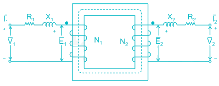
A transformer is equivalent to an ideal transformer- a)With inductive coil connected in the secondary circuit
- b)When no coils are connected to primary and secondary
- c)With inductive coil connected in only the primary circuit
- d)With inductive coils connected in both the primary and secondary circuits
Correct answer is option 'D'. Can you explain this answer?
A transformer is equivalent to an ideal transformer
a)
With inductive coil connected in the secondary circuit
b)
When no coils are connected to primary and secondary
c)
With inductive coil connected in only the primary circuit
d)
With inductive coils connected in both the primary and secondary circuits
| | Hrishikesh Yadav answered |
A transformer is equivalent to an ideal transformer with inductive coils connected in both the primary and secondary circuits.
We can represent the equivalent circuit as shown below.

In a DC machine, which of the following statement is true?- a)Compensating winding is used for neutralizing armature reaction while interpose winding is used for producing residual flux
- b)Compensating winding is used for neutralizing armature reaction while interpole winding is used for improving commutation.
- c)Compensating winding is used for improving commutation while interpole winding is used for neutralizing armature reaction
- d)Compensating winding is used for improving commutation while interpole winding is used for producing residual flux.
Correct answer is option 'B'. Can you explain this answer?
In a DC machine, which of the following statement is true?
a)
Compensating winding is used for neutralizing armature reaction while interpose winding is used for producing residual flux
b)
Compensating winding is used for neutralizing armature reaction while interpole winding is used for improving commutation.
c)
Compensating winding is used for improving commutation while interpole winding is used for neutralizing armature reaction
d)
Compensating winding is used for improving commutation while interpole winding is used for producing residual flux.
 | Constructing Careers answered |
The compensating windings consist of a series of coils embedded in slots in the pole faces. These coils are connected in series with the armature. The series-connected compensating windings produce a magnetic field, which varies directly with armature current. Because the compensating windings are wound to produce a field that opposes the magnetic field of the armature, they tend to cancel the cross magnetizing effect of the armature magnetic field.
Interpoles are similar to the main field poles and located on the yoke between the main field poles. They have windings in series with the armature winding. Interpoles have the function of reducing the armature reaction effect in the commutating zone. They eliminate the need to shift the brush assembly.
In a loaded dc motor, if the brushes are given a shift from the inter-pole axis in the direction of rotation, then the commutation will- a)Improve and the speed falls
- b)Deteriorate and the speed rises
- c)Deteriorate and the speed falls
- d)Improve and the speed rises
Correct answer is option 'C'. Can you explain this answer?
In a loaded dc motor, if the brushes are given a shift from the inter-pole axis in the direction of rotation, then the commutation will
a)
Improve and the speed falls
b)
Deteriorate and the speed rises
c)
Deteriorate and the speed falls
d)
Improve and the speed rises
 | Snehal Tiwari answered |
In a loaded dc motor, if the brushes are given a shift from the inter-pole axis in the direction of rotation, then the commutation will deteriorate
The armature reaction is partially magnetizing due to horizontal component and partially cross magnetizing due to vertical component. The flux will increase and hence there will be reduction in speed
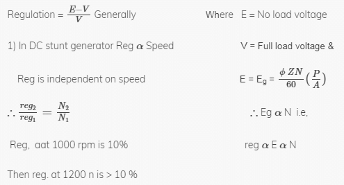
A dc shunt generator has full-load voltage regulation of 10% at rated speed of 1000 rpm. If it is now driven at 1250 rpm, then its voltage regulation at full load would
a) Be less than 10%b) Be more than 10%c) Remain unchangedd) Be 12.5%Correct answer is option 'B'. Can you explain this answer?
 | Mrinalini Sen answered |
Which of the following is an unexcited single phase synchronous motor?- a)A.C. Series motor
- b)Reluctance motor
- c)Universal motor
- d)Repulsion motor
Correct answer is option 'B'. Can you explain this answer?
Which of the following is an unexcited single phase synchronous motor?
a)
A.C. Series motor
b)
Reluctance motor
c)
Universal motor
d)
Repulsion motor
| | Mihir Chawla answered |
Unexcited single phase synchronous motor runs at constant speed equal to synchronous speed of revolving flux. They do not need a dc excitation for their rotors.
Reluctance motor and Hysteresis motors are unexcited single phase synchronous motors.
In a synchronous generator operating at zero power factor lagging. The effect of armature reaction is- a)Magnetizing
- b)Demagnetizing
- c)Cross-magnetizing
- d)Both magnetizing and cross-magnetizing
Correct answer is option 'B'. Can you explain this answer?
In a synchronous generator operating at zero power factor lagging. The effect of armature reaction is
a)
Magnetizing
b)
Demagnetizing
c)
Cross-magnetizing
d)
Both magnetizing and cross-magnetizing
 | Rahul Chauhan answered |
At lagging zero electrical power factor, the armature current lags by 90° to induced emf in the armature. As the emf induced in the armature coil due to main field flux thus the emf leads the main field flux by 90°.
Armature flux and field flux act directly opposite to each other. Hence armature reaction of the alternator at lagging zero power factor is a purely demagnetising type. That means, armature flux directly weakens main field flux.
The squirrel cage winding of a single phase motor is placed in the - a)Armature
- b)Stator
- c)Rotor
- d)Field
Correct answer is option 'C'. Can you explain this answer?
The squirrel cage winding of a single phase motor is placed in the
a)
Armature
b)
Stator
c)
Rotor
d)
Field
| | Sanya Agarwal answered |
Correct Answer :- C
Explanation : A synchronous motor may have a squirrel-cage winding embedded in its rotor, used to increase the motor starting torque and so decrease the time to accelerate to synchronous speed. The squirrel cage winding of a synchronous machine will generally be smaller than for an induction machine of similar rating. When the rotor is turning at the same speed as the stator's revolving magnetic field, no current is induced into the squirrel-cage windings and the windings will have no further effect on the operation of the synchronous motor at steady-state.
The Statement “Generators are Coherent”, implies that:- a)All of them oscillate at same frequency
- b)Each of them oscillates at different
- c)They rotate at same frequency
- d)Each generator rotates at different frequency
Correct answer is option 'A'. Can you explain this answer?
The Statement “Generators are Coherent”, implies that:
a)
All of them oscillate at same frequency
b)
Each of them oscillates at different
c)
They rotate at same frequency
d)
Each generator rotates at different frequency
| | Ravi Singh answered |
‘’Generators are Coherent’’ implies that all the generators connected in parallel to a common bus are oscillating at same frequency.
When two alternators are connected in parallel, their frequency, terminal voltage and phase angle should be equal to busbar’s frequency, terminal voltage and phase angle.
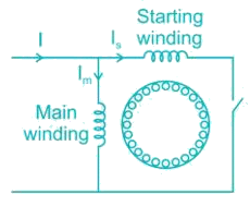
In a split phase motor, the ratio of number of turns for starting winding to that for running winding is- a)2.0
- b)>1
- c)1.0
- d)<1
Correct answer is option 'D'. Can you explain this answer?
In a split phase motor, the ratio of number of turns for starting winding to that for running winding is
a)
2.0
b)
>1
c)
1.0
d)
<1
| | Yash Patel answered |
A split-phase motor has a starting winding separate from the main winding. When the motor is starting, the starting winding is connected to the power source through a centrifugal switch which is closed at low speed. The starting winding is wound with fewer turns of smaller wire than the main winding, so it has a lower inductance (L) and higher resistance (R). The lower L/R ratio creates a small phase shift, not more than about 30 degrees between the flux due to the main winding and the flux of the starting winding.
Hence the ratio of number of turns for starting winding to that for running winding is less than 1.
The pitch factor, in rotating electrical machinery, is defined as the ratio of resultant emf of a- a)Full-pitched coil to that of a chorded coil
- b)Full-pitched coil to the phase emf
- c)Chorded coil to the phase emf
- d)Chorded coil to that of full-pitched coil
Correct answer is option 'D'. Can you explain this answer?
The pitch factor, in rotating electrical machinery, is defined as the ratio of resultant emf of a
a)
Full-pitched coil to that of a chorded coil
b)
Full-pitched coil to the phase emf
c)
Chorded coil to the phase emf
d)
Chorded coil to that of full-pitched coil
| | Ayush Kumar answered |
Pitch Factor in Rotating Electrical Machinery
The pitch factor is an important parameter in rotating electrical machinery which determines the magnitude of the induced emf in the machine. It is defined as the ratio of the emf induced in a chorded coil to the emf induced in a full-pitched coil.
Explanation
A full-pitched coil is a coil that spans the full pitch of the pole pitch of the machine. Its emf is induced by the flux linkage of the entire pole pitch. On the other hand, a chorded coil is a coil that spans only a fraction of the pole pitch. Its emf is induced by the flux linkage of only a part of the pole pitch.
The emf induced in a full-pitched coil is always greater than the emf induced in a chorded coil. This is because the full-pitched coil spans the entire pole pitch and thus experiences the maximum flux linkage. The chorded coil, on the other hand, experiences only a fraction of the total flux linkage and hence its induced emf is smaller.
The pitch factor is defined as the ratio of the emf induced in a chorded coil to the emf induced in a full-pitched coil. It is denoted by the symbol Kp and is given by the equation:
Kp = Echorded / Efull-pitched
where Echorded is the emf induced in the chorded coil and Efull-pitched is the emf induced in the full-pitched coil.
The pitch factor is an important parameter in determining the performance of rotating electrical machinery. It is used to calculate the voltage regulation, efficiency, and power factor of the machine.
Conclusion
In conclusion, the pitch factor is an important parameter in rotating electrical machinery that determines the magnitude of the induced emf in the machine. It is defined as the ratio of the emf induced in a chorded coil to the emf induced in a full-pitched coil. The pitch factor is used to calculate the performance of the machine and is an important parameter in the design and analysis of electrical machines.
A fluctuating voltage supply is detrimental to a refrigerator motor, but not a ceiling fan motor, although both are single-phase induction motors because, the refrigerator motor- a)Is made more robust than the fan motor
- b)Is subjected to short duty cycle but the fan motor is subjected to continuous duty
- c)Is enclosed in a sealed unit while the fan motor is open to the environment
- d)Load is constant, but the fan motor load is voltage dependent.
Correct answer is option 'C'. Can you explain this answer?
A fluctuating voltage supply is detrimental to a refrigerator motor, but not a ceiling fan motor, although both are single-phase induction motors because, the refrigerator motor
a)
Is made more robust than the fan motor
b)
Is subjected to short duty cycle but the fan motor is subjected to continuous duty
c)
Is enclosed in a sealed unit while the fan motor is open to the environment
d)
Load is constant, but the fan motor load is voltage dependent.
| | Hiral Sharma answered |
A fluctuating voltage supply is detrimental to a refrigerator motor, but not a ceiling fan motor because the refrigerator motor is enclosed in a sealed unit while the fan motor is open to the environment.
Slip rings and brushes are found in:- a)Wound rotor
- b)Squirrel cage rotor
- c)Both of the above
- d)Neither wound nor squirrel cage rotor
Correct answer is option 'A'. Can you explain this answer?
Slip rings and brushes are found in:
a)
Wound rotor
b)
Squirrel cage rotor
c)
Both of the above
d)
Neither wound nor squirrel cage rotor
| | Yash Patel answered |
In squirrel cage type rotors, the rotor bar is permanently shorted at the end of the ring. Hence slip rings and brushes are not present in these type of rotors
Slip rings and brushes are present in wound type rotor
Iron losses of transformer are measured by- a)Low pf wattmeter
- b)Unity pf wattmeter
- c)Any type of wattmeter
- d)None of these
Correct answer is option 'A'. Can you explain this answer?
Iron losses of transformer are measured by
a)
Low pf wattmeter
b)
Unity pf wattmeter
c)
Any type of wattmeter
d)
None of these
| | Neha Choudhury answered |
Eddy current losses are caused by currents induced in the iron due to the alternating flux. In contrast to the parallel shunt component, the series component in the circuit diagram represents the winding losses due to the resistance of the coil windings of the transformer.is Low pf wattmeter.
What does happen if tripled harmonics given to induction motor?- a)Will results in short circuit
- b)Fail to start
- c)Nothing will happen
- d)None of the above
Correct answer is option 'B'. Can you explain this answer?
What does happen if tripled harmonics given to induction motor?
a)
Will results in short circuit
b)
Fail to start
c)
Nothing will happen
d)
None of the above
| | Saumya Basak answered |
When a sinusoidal input is applied to electronic circuit the output is distorted wave form. This distorted wave is because of nonlinear characteristics of electronic circuit. Those distorted wave is called harmonics. The component having triple times of the fundamental are known as third harmonics. Generally all third harmonics are equal in all phases.
When these harmonics is applied to induction motor, it will fail to start because rotating magnetic field won’t develop.
As compared to D.O.L. starter, star delta starter operates at:- a)Full voltage
- b)72% of full voltage
- c)58% of full voltage
- d)34% of full voltage
Correct answer is option 'C'. Can you explain this answer?
As compared to D.O.L. starter, star delta starter operates at:
a)
Full voltage
b)
72% of full voltage
c)
58% of full voltage
d)
34% of full voltage
| | Alok Khanna answered |
In case of star delta starter, the stator terminals are first connected in star. In star connection, phase voltage is 0.577 times the line voltage. If connected in delta, the line and phase voltage are same.
Now, current through each phase winding is equal to Phase Voltage/impedance of the winding. So, if phase Voltage is reduced, the starting current can be reduced because the impedance remains constant. That's why the motor is started in star connection where voltage reduces by √3 times or 0.577 times thus reducing the starting current.
Hence as compared to D.O.L. starter, star delta starter operates at 58% of full voltage.
Which test on transformer provides information about regulation efficiency and heating under load conditions?- a)Open circuit test
- b)Back to back test
- c)Hopkinson test
- d)Short circuit test
Correct answer is option 'B'. Can you explain this answer?
Which test on transformer provides information about regulation efficiency and heating under load conditions?
a)
Open circuit test
b)
Back to back test
c)
Hopkinson test
d)
Short circuit test
| | Nayanika Singh answered |
Back to back test on transformer is a method for determining transformer efficiency, voltage regulation and heating under loaded conditions. In this method, two identical transformers are connected back to back such that their primaries are in parallel across the same voltage source and the secondaries in series so that one transformer is loaded on the other.
Short circuit and open circuit tests on transformer can give us parameters of equivalent circuit of transformer but they cannot help us in finding the heating information.
A 3-phase induction motor is running on a constant load. If the fuse in one phase blows off the- a)Motor will stop
- b)Motor will run with reduced current
- c)Motor will run with increased current
- d)None of the other options
Correct answer is option 'C'. Can you explain this answer?
A 3-phase induction motor is running on a constant load. If the fuse in one phase blows off the
a)
Motor will stop
b)
Motor will run with reduced current
c)
Motor will run with increased current
d)
None of the other options
| | Krish Saini answered |
When a three-phase motor loses one of the phase supply voltage then it is called single phasing. Single phasing is a case when any one phase out of the three phases fails.
Since one of the phases is now disconnected, current through other two phases will increase to produce the desired torque. The motor will run but would not be able to drive rated load. The uneven torque results in abnormal noise and vibration in motor.
Why is the air gap between the yoke and armature of an electric motor kept smaller?- a)To achieve a stronger magnetic field
- b)To avoid overheating of the machine
- c)To make station easier
- d)None of these
Correct answer is option 'A'. Can you explain this answer?
Why is the air gap between the yoke and armature of an electric motor kept smaller?
a)
To achieve a stronger magnetic field
b)
To avoid overheating of the machine
c)
To make station easier
d)
None of these
| | Rajesh Saha answered |
The magnetic field always chooses the low reluctance path hence to achieve a strong magnetic field we need to maintain low reluctance path. It can be achieved by keeping smaller air gap between the yoke and armature of an electric motor.
For a particular kW rating of an induction motor, the kVAR rating of the shunt capacitor required is _______.- a)More for high rated speed motor
- b)More for lower rated speed motor
- c)Independent of speed
- d)None of these
Correct answer is option 'B'. Can you explain this answer?
For a particular kW rating of an induction motor, the kVAR rating of the shunt capacitor required is _______.
a)
More for high rated speed motor
b)
More for lower rated speed motor
c)
Independent of speed
d)
None of these
| | Saumya Sen answered |
At higher rated speeds, slip is low. At lower slip values, power factor is high. Hence the required kVAR rating of the shunt capacitor is less for high rated speed motor.
At lower rated speeds, slip is high. At higher slip values, power factor is low. Hence the required kVAR rating of the shunt capacitor is more for lower rated speed motor.
Which DC motor has got maximum self-loading property?- a)Series motor
- b)Shunt motor
- c)Cumulatively compounded motor
- d)Differentially compounded motor
Correct answer is option 'D'. Can you explain this answer?
Which DC motor has got maximum self-loading property?
a)
Series motor
b)
Shunt motor
c)
Cumulatively compounded motor
d)
Differentially compounded motor
| | Gayatri Menon answered |
In a differentially compound DC motor at higher values of load, the flux reduces so sharply at small increase in load. It is advisable that motor should not be used beyond some load value, as it may damage itself by self-loading.
Reluctance torque in rotating machines is present when_______- a)Airgap is not uniform
- b)Reluctance seen by rotor mmf is constant
- c)Reluctance seen by rotor mmf varies
- d)None of these
Correct answer is option 'A'. Can you explain this answer?
Reluctance torque in rotating machines is present when_______
a)
Airgap is not uniform
b)
Reluctance seen by rotor mmf is constant
c)
Reluctance seen by rotor mmf varies
d)
None of these
| | Sreemoyee Deshpande answered |
Metals like Iron provide a low reluctance path and the flux lines like to pass through the least reluctance path. The least reluctance path is along the pole axis where the air gap is minimum. So the flux lines will exert force on the rotor to align with the flux lines. This torque is created additional to the torque produced by the locking of excited poles with synchronously rotating magnetic field. This effect is absent in cylindrical rotor machine as the air gap is uniform.
Booster transformer are used to:- a)To change the voltage magnitude and phase angle
- b)Reduce the voltage magnitude
- c)Increase the voltage magnitude
- d)To change the voltage phase angle
Correct answer is option 'C'. Can you explain this answer?
Booster transformer are used to:
a)
To change the voltage magnitude and phase angle
b)
Reduce the voltage magnitude
c)
Increase the voltage magnitude
d)
To change the voltage phase angle
| | Bibek Saha answered |
Booster transformer is used towards the end of a power line to raise the voltage to the desired value. It is used for controlling the voltage of a feeder at a point far away from the main transformer.
The secondary of the booster transformer is connected in series with the line, and its primary is supplied from the secondary of the regulating transformer.
Booster transformer is used in railways for eliminating the flow of stray current. The stray current disturbs the communication system and also damage the electronic devices of the trains passing through them.
For an induction motor the torque is proportional to the product of:- a)Current and power factor of the motor
- b)Current and Impedance of the motor
- c)Flux and current
- d)Current and power factor of the motor and flux
Correct answer is option 'D'. Can you explain this answer?
For an induction motor the torque is proportional to the product of:
a)
Current and power factor of the motor
b)
Current and Impedance of the motor
c)
Flux and current
d)
Current and power factor of the motor and flux
| | Rajesh Kumar answered |
The torque of an induction motor is,
T∝ϕI2cosϕ2
Where, ϕ is the flux
I2 is rotor current at standstill condition
ϕ2 is the angle between rotor emf and rotor current
Consider the following statements regarding synchronous machines:1. In an alternator, armature mmf leads the field flux2. In an alternator, airgap flux lags the field flux3. In a synchronous motor, armature mmf leads the field flux4. In an alternator, field flux lags the armature currentFrom these, the correct answer is- a)2, 3
- b)1, 3, 4
- c)2, 3, 4
- d)1, 2, 3
Correct answer is option 'A'. Can you explain this answer?
Consider the following statements regarding synchronous machines:
1. In an alternator, armature mmf leads the field flux
2. In an alternator, airgap flux lags the field flux
3. In a synchronous motor, armature mmf leads the field flux
4. In an alternator, field flux lags the armature current
From these, the correct answer is
a)
2, 3
b)
1, 3, 4
c)
2, 3, 4
d)
1, 2, 3
| | Kunal Sharma answered |
1. In an alternator, armature mmf lags the field flux
2. In an alternator, airgap flux lags the field flux
3. In a synchronous motor, armature mmf leads the field flux
4. In an alternator, field flux leads the armature current
The injected emf in the rotor of induction motor must have- a)The same frequency as the slip frequency
- b)The same phase as the rotor emf
- c)A high value for satisfactory speed control
- d)The same phase as the rotor emf and a high value for satisfactory speed control
Correct answer is option 'A'. Can you explain this answer?
The injected emf in the rotor of induction motor must have
a)
The same frequency as the slip frequency
b)
The same phase as the rotor emf
c)
A high value for satisfactory speed control
d)
The same phase as the rotor emf and a high value for satisfactory speed control
| | Sravya Khanna answered |
When the speed control of three phase induction motor is done by adding resistance in rotor circuit, some part of power called, the slip power is lost. Therefore the efficiency of three phase induction motor is reduced by this method of speed control.
This slip power loss can be recovered and supplied back to improve the overall efficiency of the three-phase induction motor. This scheme of recovering the power is called slip power recovery scheme and this is done by connecting an external source of emf of slip frequency to the rotor circuit.
The injected emf can either oppose the rotor induced emf or aids the rotor induced emf. If it opposes the rotor induced emf, the total rotor resistance increases and hence the speed is decreased and if the injected emf aids the main rotor emf the total decreases and hence speed increases.
The no load primary input is approximately equal to the:- a)Iron loss of transformer
- b)Sum of Iron loss and copper loss of transformer
- c)Neither Iron loss of transformer nor copper
- d)Copper loss of transformer
Correct answer is option 'A'. Can you explain this answer?
The no load primary input is approximately equal to the:
a)
Iron loss of transformer
b)
Sum of Iron loss and copper loss of transformer
c)
Neither Iron loss of transformer nor copper
d)
Copper loss of transformer
| | Abhishek Chauhan answered |
When transformer is operated at no load, its secondary winding is open circuited or no load is connected to the secondary winding and hence no current flows through it.
When we apply a primary input voltage, the current produced in the primary winding will supply the core losses (ohmic loss are almost negligible) and would magnetize the core producing mutual flux. This current would be very small in magnitude as it induces a back emf in the primary winding.
Synchronous generator can _________ reactive power:- a)Neither generates nor absorbs
- b)Absorb
- c)Generate and absorb
- d)Generate
Correct answer is option 'C'. Can you explain this answer?
Synchronous generator can _________ reactive power:
a)
Neither generates nor absorbs
b)
Absorb
c)
Generate and absorb
d)
Generate
| | Dhruv Datta answered |
The reactive power of a synchronous generator is given by,
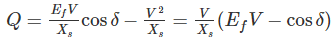
1) When EfV = cosδ then generator works under unity power factor condition
2) When EfV > cosδ then reactive power will be positive, i.e. generator supplies reactive power
3) When EfV < cosδ then reactive power will be negative, i.e. generator absorbs reactive power
In case of four pole, lap wound machine if the air gap under each pole is the same, then what will be the result?- a)There will be reduced eddy current
- b)There will be reduced hysteresis loss
- c)Current in each path will not be the same
- d)It will result in higher terminal voltage
Correct answer is option 'B'. Can you explain this answer?
In case of four pole, lap wound machine if the air gap under each pole is the same, then what will be the result?
a)
There will be reduced eddy current
b)
There will be reduced hysteresis loss
c)
Current in each path will not be the same
d)
It will result in higher terminal voltage
| | Sreemoyee Deshpande answered |
In case of lap wound, number of parallel paths (A) = number of poles (P)
The current in the each path will be same.
The terminal voltage will be higher in wave wound machine
In lap wound machine, the hysteresis losses will be reduced whereas eddy current losses will be reduced in wave wound machine
The given figure depicts the Torque-Current characteristics of: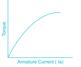
- a)Series motor
- b)Shunt motor
- c)Cumulative compound motor
- d)Differential compound motor
Correct answer is option 'D'. Can you explain this answer?
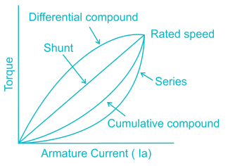
The given figure depicts the Torque-Current characteristics of:
a)
Series motor
b)
Shunt motor
c)
Cumulative compound motor
d)
Differential compound motor
| | Deepika Saha answered |
We can observe the torque current characteristics of different DC motors as shown below
The maximum efficiency of a 100 kVA transformer having iron loss of 900 kW and full load Cu loss of 1600 W occurs at________kVA.- a)56.3
- b)133.3
- c)75
- d)177.7
Correct answer is option 'C'. Can you explain this answer?
The maximum efficiency of a 100 kVA transformer having iron loss of 900 kW and full load Cu loss of 1600 W occurs at________kVA.
a)
56.3
b)
133.3
c)
75
d)
177.7
| | Neha Choudhury answered |
Maximum efficiency at = kVA X √( Wi / Wcu )
= kVA X √ ( 900 / 1600 ) = 75 % of full load.
Where Wi = iron loss, Wcu = copper loss.
In lap winding, the number of brushes is always- a)Double the number of pole
- b)Same as the number of poles
- c)Half the number of poles
- d)Triple the number of poles
Correct answer is option 'B'. Can you explain this answer?
In lap winding, the number of brushes is always
a)
Double the number of pole
b)
Same as the number of poles
c)
Half the number of poles
d)
Triple the number of poles
| | Manasa Bose answered |
In lap winding, the number of parallel paths = number of brushes = number of poles
In wave winding, the number of parallel paths = number of brushes = 2
Consider the following steps1) Reversing connections to the terminals of the capacitor2) Changing the position of the capacitor from auxiliary winding circuit to main winding circuit3) Reversing supply connection to the main winding4) Reversing supply connection to the auxiliary circuitWhile installing a new ceiling fan, if the fan motor is found to be rotating in the wrong directions then the direction of rotation of fan motor can be corrected by- a)1, 2 and 3
- b)1, 2 and 4
- c)1, 3 and 4
- d) 2, 3 and 4
Correct answer is option 'C'. Can you explain this answer?
Consider the following steps
1) Reversing connections to the terminals of the capacitor
2) Changing the position of the capacitor from auxiliary winding circuit to main winding circuit
3) Reversing supply connection to the main winding
4) Reversing supply connection to the auxiliary circuit
While installing a new ceiling fan, if the fan motor is found to be rotating in the wrong directions then the direction of rotation of fan motor can be corrected by
a)
1, 2 and 3
b)
1, 2 and 4
c)
1, 3 and 4
d)
2, 3 and 4
| | Samarth Khanna answered |
Explanation:
The direction of rotation of a ceiling fan motor depends on the phase relationship between the main winding and the auxiliary winding of the motor. If the fan motor is found to be rotating in the wrong direction, it can be corrected by following the given steps:
Step 1: Reversing connections to the terminals of the capacitor
The capacitor is connected in series with the auxiliary winding of the motor. By reversing the connections to the terminals of the capacitor, the phase relationship between the main winding and the auxiliary winding can be changed, which will result in a reversal of the direction of rotation of the motor.
Step 2: Changing the position of the capacitor from auxiliary winding circuit to main winding circuit
The position of the capacitor determines its effect on the phase relationship between the main winding and the auxiliary winding. By moving the capacitor from the auxiliary winding circuit to the main winding circuit, the phase relationship can be changed, leading to a reversal of the direction of rotation of the motor.
Step 3: Reversing supply connection to the main winding
The direction of rotation of the motor depends on the phase of the voltage applied to the main winding. By reversing the supply connection to the main winding, the phase of the voltage applied to the winding is changed, resulting in a reversal of the direction of rotation of the motor.
Step 4: Reversing supply connection to the auxiliary circuit
Similar to the main winding, the direction of rotation of the motor also depends on the phase of the voltage applied to the auxiliary winding. By reversing the supply connection to the auxiliary circuit, the phase of the voltage applied to the winding is changed, which will result in a reversal of the direction of rotation of the motor.
Therefore, to correct the direction of rotation of a ceiling fan motor, all four steps mentioned above need to be followed. Hence, the correct answer is option 'C' (2, 3, and 4).
The induction motors develop which of the following at low frequency of the order ½ Hz to 10 Hz?- a)High starting torque with excessive starting current
- b)High starting torque without excessive starting current
- c)Low starting torque with excessive starting current
- d)Low starting torque without excessive starting current
Correct answer is option 'B'. Can you explain this answer?
The induction motors develop which of the following at low frequency of the order ½ Hz to 10 Hz?
a)
High starting torque with excessive starting current
b)
High starting torque without excessive starting current
c)
Low starting torque with excessive starting current
d)
Low starting torque without excessive starting current
| | Shanaya Mehta answered |
The starting torque of an induction motor is given by,
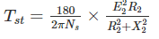
The starting torque is inversely proportional to frequency.
At low frequency operation of induction motors, the starting torque will become high without any excessive starting current
Alternators are classified into - a)Salient pole and non-salient pole
- b)Slip ring and squirrel cage
- c)Self-starting and separately excited
- d)None of these
Correct answer is option 'A'. Can you explain this answer?
Alternators are classified into
a)
Salient pole and non-salient pole
b)
Slip ring and squirrel cage
c)
Self-starting and separately excited
d)
None of these
| | Siddharth Datta answered |
Alternators are classified into salient pole and non-salient pole machines.
In salient pole type of rotor consist of large number of projected poles (salient poles) mounted on a magnetic wheel. Typically number of salient poles are 4 to 60. Salient pole rotors have large diameter and shorter axial length. Flux distribution is relatively poor than non-salient pole rotor, hence the generated emf waveform is not as good as cylindrical rotor.
Non-salient pole rotors are cylindrical in shape having parallel slots on it to place rotor windings. Number of poles is usually 2 or 4. They are smaller in diameter but having longer axial length. Flux distribution is sinusoidal and hence gives better emf waveform.
If a 3-phase alternator is short-circuited at its terminal, then the initial value of short-circuit current will be limited by ________.- a)Synchronous reactance
- b)Transient reactance
- c)Sub transient reactance
- d)None of these
Correct answer is option 'B'. Can you explain this answer?
If a 3-phase alternator is short-circuited at its terminal, then the initial value of short-circuit current will be limited by ________.
a)
Synchronous reactance
b)
Transient reactance
c)
Sub transient reactance
d)
None of these
| | Sreemoyee Deshpande answered |
If a 3-phase alternator is short-circuited at its terminal, then the current in all three phases will become very high (15 times of the full load current). The reactance will become least and this is called sub transient reactance.
In an induction motor, if the rotor resistance is equal to standstill reactance then the maximum torque is- a)Less than starting torque
- b)Equal to starting torque
- c)More than starting torque
- d)None of these
Correct answer is option 'B'. Can you explain this answer?
In an induction motor, if the rotor resistance is equal to standstill reactance then the maximum torque is
a)
Less than starting torque
b)
Equal to starting torque
c)
More than starting torque
d)
None of these
| | Tanishq Menon answered |
At maximum torque, rotor resistance is equal to slip times of reactance.

At starting condition (s = 1), rotor resistance is equal to standstill reactance.
The machine which is designed to run without an active load but with its excitation to produce reactive power is called- a)An induction motor
- b)A synchronous motor
- c)A synchronous generator
- d)A synchronous compensator
Correct answer is option 'D'. Can you explain this answer?
The machine which is designed to run without an active load but with its excitation to produce reactive power is called
a)
An induction motor
b)
A synchronous motor
c)
A synchronous generator
d)
A synchronous compensator
| | Preethi Datta answered |
Synchronous compensator is a DC-excited synchronous motor, whose shaft is not connected to anything but spin freely. Its purpose is not to convert electric power to mechanical power or vice versa, but to adjust conditions on the electric power transmission grid. Its field is controlled by a voltage regulator to either generate or absorb reactive power as needed to adjust the grid's voltage or to improve power factor.
The sheet steel material used in transformer core has:- a)High core loss and low permeability
- b)Low core loss and low permeability
- c)Low core loss and high permeability
- d)High core loss and high permeability
Correct answer is option 'C'. Can you explain this answer?
The sheet steel material used in transformer core has:
a)
High core loss and low permeability
b)
Low core loss and low permeability
c)
Low core loss and high permeability
d)
High core loss and high permeability
| | Athul Banerjee answered |
Low core loss and high permeability are the characteristics of the sheet steel material used in transformer cores. This choice, option C, is the correct answer.
Explanation:
Core loss refers to the energy lost in the form of heat when an alternating magnetic field is applied to a core material. It is an important consideration in transformer design because excessive core loss can result in reduced efficiency and increased operating temperatures. On the other hand, permeability is a measure of how easily a material can be magnetized or how well it can conduct magnetic flux.
The sheet steel material used in transformer cores is specifically chosen for its low core loss and high permeability properties due to the following reasons:
1. Low Core Loss:
Sheet steel materials used in transformer cores are designed to have low core loss characteristics. This means that they have a low hysteresis loss and eddy current loss when subjected to varying magnetic fields. Low hysteresis loss is achieved by using steel with low coercivity, which means it requires less energy to magnetize and demagnetize the material. Low eddy current loss is achieved by using materials with high resistivity or by laminating the steel sheets to minimize the flow of eddy currents.
2. High Permeability:
High permeability is desired in transformer cores as it allows for efficient magnetic flux conduction. A material with high permeability can easily magnetize and demagnetize, resulting in a more effective transfer of energy. Sheet steel materials for transformer cores are carefully processed to enhance their magnetic properties, such as grain orientation and controlled annealing, to achieve high permeability.
By selecting sheet steel materials with low core loss and high permeability, transformer designers can minimize energy losses and improve the efficiency of the transformer. This allows for the efficient transfer of electrical energy from one circuit to another with minimal losses and ensures that the transformer operates within acceptable temperature limits.
In conclusion, the sheet steel material used in transformer cores has low core loss and high permeability properties to ensure efficient energy transfer and minimize losses.
The open slots are more commonly used in the stator of a synchronous machine because _______.A. The inductance of the winding is lessB. They facilitate the insertion of form wound and insulated coils- a)Only A
- b)Only B
- c)Both A and B
- d)None of these
Correct answer is option 'C'. Can you explain this answer?
The open slots are more commonly used in the stator of a synchronous machine because _______.
A. The inductance of the winding is less
B. They facilitate the insertion of form wound and insulated coils
a)
Only A
b)
Only B
c)
Both A and B
d)
None of these
| | Tanishq Majumdar answered |
Leakage reactance is less in open type slots. Therefore more amount of power will be transferred from stator to rotor and torque production is high. Windings can be placed in to the slots very easily.
A 3-phase induction motor when started picks up speed but runs stably at about half the normal speed. This is because of:- a)Unbalance in the supply voltages
- b)Non-sinusoidal nature of the supply voltage
- c)Stator circuit asymmetry
- d)Rotor circuit asymmetry
Correct answer is option 'B'. Can you explain this answer?
A 3-phase induction motor when started picks up speed but runs stably at about half the normal speed. This is because of:
a)
Unbalance in the supply voltages
b)
Non-sinusoidal nature of the supply voltage
c)
Stator circuit asymmetry
d)
Rotor circuit asymmetry
| | Mansi Datta answered |
A 3-phase induction motor when started picks up speed but runs stably at about half the normal speed. This happens because of the non-sinusoidal nature of the supply voltage.
In a single-phase induction motor the stator winding produces a flux which is:- a)Alternating
- b)Alternating and Rotating
- c)Rotating
- d)Constant everywhere
Correct answer is option 'A'. Can you explain this answer?
In a single-phase induction motor the stator winding produces a flux which is:
a)
Alternating
b)
Alternating and Rotating
c)
Rotating
d)
Constant everywhere
| | Mira Mukherjee answered |
Introduction:
A single-phase induction motor is a type of electric motor that operates on single-phase power supply. It is commonly used in household appliances, small industrial machinery, and other applications where only a single-phase power supply is available. The stator winding in a single-phase induction motor is responsible for generating the magnetic field required for motor operation.
Explanation:
The stator winding in a single-phase induction motor produces a flux that is alternating in nature. This means that the magnetic field generated by the stator winding changes its direction periodically over time. This alternating flux is necessary for the motor to operate.
Reason:
The reason why the stator winding produces an alternating flux is due to the nature of the single-phase power supply. In a single-phase system, the voltage and current waveform alternate in polarity and direction over time. This causes the magnetic field produced by the stator winding to also alternate in direction.
Effect:
The alternating flux produced by the stator winding interacts with the rotor conductors, inducing currents in them. These currents create a magnetic field in the rotor, which interacts with the stator field to produce a torque. This torque causes the rotor to rotate and drives the motor.
Conclusion:
In conclusion, the stator winding in a single-phase induction motor produces an alternating flux. This alternating flux is necessary for the motor to operate and generate the torque required for rotation. Understanding the nature of the flux produced by the stator winding is crucial in designing and analyzing the performance of single-phase induction motors.
Which of the following is true for a synchronous condenser?- a)It is a synchronous motor with capacitor connected across stator terminals to improve power factor
- b)It is a synchronous motor operating at full load with leading power factor
- c)It is an over-excited synchronous motor partially supplying mechanical load, and also improving power factor of the system to which it is connected
- d)It is an over-excited synchronous motor operating at no-load with leading power factor used in large power stations for improvement of power factor
Correct answer is option 'D'. Can you explain this answer?
Which of the following is true for a synchronous condenser?
a)
It is a synchronous motor with capacitor connected across stator terminals to improve power factor
b)
It is a synchronous motor operating at full load with leading power factor
c)
It is an over-excited synchronous motor partially supplying mechanical load, and also improving power factor of the system to which it is connected
d)
It is an over-excited synchronous motor operating at no-load with leading power factor used in large power stations for improvement of power factor
| | Raghav Nambiar answered |
Synchronous condenser is an over-excited synchronous motor operating at no-load with leading power factor.
The efficiency of long power transmission lines may be increased by placing synchronous condensers along the line to compensate lagging currents caused by line inductance.
More real power may be transmitted through a fixed size line if the power factor is brought closer to unity by synchronous condensers absorbing reactive power.
The ability of synchronous condensers to absorb or produce reactive power on a transient basis stabilizes the power grid against short circuits and other transient fault conditions
A capacitor-start single phase induction motor is switched on to supply with its capacitor and replaced by an inductor of equivalent reactance value. It will:- a)Start and then stop
- b)Start and run slowly
- c)Start and run at a rated speed
- d)Not start at all
Correct answer is option 'D'. Can you explain this answer?
A capacitor-start single phase induction motor is switched on to supply with its capacitor and replaced by an inductor of equivalent reactance value. It will:
a)
Start and then stop
b)
Start and run slowly
c)
Start and run at a rated speed
d)
Not start at all
| | Anirban Chawla answered |
In 1-phase induction motors, we are unable to get starting torque. So, we mostly use permanent capacitor split phase starting method. Its main aim is to split the single-phase supply into 2 phases, having time displacement of 90 degrees, also mechanically the 2 windings are placed 90 degrees in space. It gives rotating magnetic field which produces a starting torque & makes it a self-starting motor.
If inductor is used, the motor would not start even if having same reactance. Since coils are inductive so a capacitor or some phase splitting is necessary.
Due to low supply voltage for a 40 HP, 3-phase induction motor, which of the following equipment can be used to boost the voltage?- a)Synchronous condenser
- b)Additional tap changing transformer
- c)Series capacitors
- d)Shunt capacitor
Correct answer is option 'D'. Can you explain this answer?
Due to low supply voltage for a 40 HP, 3-phase induction motor, which of the following equipment can be used to boost the voltage?
a)
Synchronous condenser
b)
Additional tap changing transformer
c)
Series capacitors
d)
Shunt capacitor
| | Madhurima Banerjee answered |
A synchronous condenser is an overexcited synchronous motor, which draws leading currents from the system and hence compensates for lagging vars. It is used as a reactive power compensator in some systems for power factor correction purposes.
A tap changer is a mechanism in transformers which allows for variable turn ratios to be selected in discrete steps. These are often placed on the high voltage (low current) transformer winding for easy access and to minimize the current load during operation
Series capacitors are used to compensate the inductance of transmission line. Series capacitors will increase the transmission capacity and the stability of the line.
Shunt capacitor banks are primarily used to improve the power factor in the network. They also improve the voltage stability and reduce network losses.
Hence shunt capacitor should be used to boost the voltage.
Skewing of the rotor in a three-phase squirrel-cage induction motor reduces- a)Noise, parasitic torque, starting torque and pullout torque
- b)Noise and parasitic torque, but increase starting torque and pollout torque
- c)Noise and pollout torque, but increase parasitic torque and starting torque
- d)Noise parasitic torque and starting torque, but increased pullout torque
Correct answer is option 'A'. Can you explain this answer?
Skewing of the rotor in a three-phase squirrel-cage induction motor reduces
a)
Noise, parasitic torque, starting torque and pullout torque
b)
Noise and parasitic torque, but increase starting torque and pollout torque
c)
Noise and pollout torque, but increase parasitic torque and starting torque
d)
Noise parasitic torque and starting torque, but increased pullout torque
| | Rajdeep Gupta answered |
If the rotor slots are skewed then the effect of slot harmonics (parasitic torques) can be eliminated.
Since the skewed rotor slot is not parallel to start slot in an induction motor, there is more leakage reactance. As a result, induction motor has lower starting and maximum torques.
With skewed rotor bars, the revolving flux, in effect, encounters an air gap of uniform reluctance and this results in a uniform torque and quieter operation.
The voltage applied to a transformer primary is increased by keeping v/f ratio constant, with this the core loss will- a)Decrease and magnetizing current Im will increase
- b)Increase and Im will also increase
- c)remain constant and Im will remain constant
- d)Increase and Im will remain constant
Correct answer is option 'D'. Can you explain this answer?
The voltage applied to a transformer primary is increased by keeping v/f ratio constant, with this the core loss will
a)
Decrease and magnetizing current Im will increase
b)
Increase and Im will also increase
c)
remain constant and Im will remain constant
d)
Increase and Im will remain constant
| | Sankar Rane answered |
As v/f ratio is constant.
If v increases, f also increases.
As frequency increases, core losses also increases.
We know that, 
As v and f both increases, flux remain constant and hence magnetizing current will remain constant.
Torques developed by a split phase motor is proportional to - a)Sine of angle between Im and Is
- b)Cosine of angle between Im and Is
- c)Main winding current Is
- d)Auxiliary winding current Is
Correct answer is option 'A'. Can you explain this answer?
Torques developed by a split phase motor is proportional to
a)
Sine of angle between Im and Is
b)
Cosine of angle between Im and Is
c)
Main winding current Is
d)
Auxiliary winding current Is
| | Nilesh Verma answered |
A split-phase motor has no capacitance in the auxiliary circuit. A phase shift with respect to the main current is achieved by using narrow conductors to achieve a high resistance to reactance ratio.
Increasing the resistance means that the auxiliary winding can only be used during starting, otherwise, it would overheat.
A split-phase motor has significantly lower torque at starting than any of the capacitor motors due to the reduced phase angle between main and starting winding currents.
Torques developed by a split phase motor is proportional to sine of angle between Im and Is
To reduce the peripheral speed of an alternator, diameter of the rotor is:- a)Increased
- b)Decreased
- c)Increased or decreased
- d)Kept same
Correct answer is option 'B'. Can you explain this answer?
To reduce the peripheral speed of an alternator, diameter of the rotor is:
a)
Increased
b)
Decreased
c)
Increased or decreased
d)
Kept same
| | Mira Mukherjee answered |
Peripheral speed refers to the speed on the periphery or the circumference of the rotor. The peripheral speed is given by the product of the circumference and the speed.
Ps = π × D × RPM
The peripheral speed is dependent on the speed as well as the diameter of the rotor.
Hence to reduce the peripheral speed of an alternator, we need to reduce the diameter of the rotor and increase the axial length.
Which of the following is not necessarily the advantage of D.C motor over A.C Motor?- a)High starting torque
- b)Wide speed range
- c)Better speed control
- d)Low cost
Correct answer is option 'D'. Can you explain this answer?
Which of the following is not necessarily the advantage of D.C motor over A.C Motor?
a)
High starting torque
b)
Wide speed range
c)
Better speed control
d)
Low cost
| | Amar Desai answered |
DC motors have the advantage of
1. Higher starting torque
2. Quick starting and stopping, reversing
3. Variable speeds with voltage input and they are easier to control than AC
The common type of servo motor is different from normal induction motor as it has: - a)Lower rotor resistance
- b)Higher rotor resistance
- c)Higher power rating
- d)Large inertia
Correct answer is option 'B'. Can you explain this answer?
The common type of servo motor is different from normal induction motor as it has:
a)
Lower rotor resistance
b)
Higher rotor resistance
c)
Higher power rating
d)
Large inertia
| | Harsh Khanna answered |
The differences between servo motor and induction motor are:
1) Servo motor is closed loop system where as induction motor is an open loop system
2) An induction motor has high inertia and servo motor has a very low inertia. Hence servo motors are used in applications where instant and accurate positioning of load is required
3) Servo motor has high rotor resistance and low power rating compared to induction motor
Chapter doubts & questions for Electrical Machines - SSC JE Electrical Mock Test Series 2026 2026 is part of Electrical Engineering (EE) exam preparation. The chapters have been prepared according to the Electrical Engineering (EE) exam syllabus. The Chapter doubts & questions, notes, tests & MCQs are made for Electrical Engineering (EE) 2026 Exam. Find important definitions, questions, notes, meanings, examples, exercises, MCQs and online tests here.
Chapter doubts & questions of Electrical Machines - SSC JE Electrical Mock Test Series 2026 in English & Hindi are available as part of Electrical Engineering (EE) exam. Download more important topics, notes, lectures and mock test series for Electrical Engineering (EE) Exam by signing up for free.
SSC JE Electrical Mock Test Series 20262 videos|1 docs|55 tests |