


All Exams > Electrical Engineering (EE) > RRB JE for Electrical Engineering > All Questions
All questions of Electrical Machines for Electrical Engineering (EE) Exam
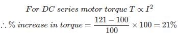
If the supply voltage of 3-phase induction motor is increased two times, then, torque is .- a)increased two times
- b)decreased two times
- c)increased four times
- d)decreased four times
Correct answer is option 'C'. Can you explain this answer?
If the supply voltage of 3-phase induction motor is increased two times, then, torque is .
a)
increased two times
b)
decreased two times
c)
increased four times
d)
decreased four times
 | Preety Kumari answered |
C. bcuz torque is directly proportional to square of the voltage in 3 phase induction motors so as we increase voltage 2 times then torque will be (2)^2=4 times

The operation of an induction motor is based on- a)Lenz's law
- b)ampere's law
- c)Mutual induction
- d)self induction
Correct answer is option 'A'. Can you explain this answer?
The operation of an induction motor is based on
a)
Lenz's law
b)
ampere's law
c)
Mutual induction
d)
self induction
| | Avinash Mehta answered |
Basic Working Principle Of An Induction Motor:
In a DC motor, supply is needed to be given for the stator winding as well as the rotor winding. But in an induction motor only the stator winding is fed with an AC supply.
1. Alternating flux is produced around the stator winding due to AC supply. This alternating flux revolves with synchronous speed. The revolving flux is called as "Rotating Magnetic Field" (RMF).
2. The relative speed between stator RMF and rotor conductors causes an induced emf in the rotor conductors, according to the Faraday's law of electromagnetic induction. The rotor conductors are short circuited, and hence rotor current is produced due to induced emf. That is why such motors are called as induction motors.
(This action is same as that occurs in transformers, hence induction motors can be called as rotating transformers.)
3. Now, induced current in rotor will also produce alternating flux around it. This rotor flux lags behind the stator flux. The direction of induced rotor current, according to Lenz's law, is such that it will tend to oppose the cause of its production.
4. As the cause of production of rotor current is the relative velocity between rotating stator flux and the rotor, the rotor will try to catch up with the stator RMF. Thus the rotor rotates in the same direction as that of stator flux to minimize the relative velocity. However, the rotor never succeeds in catching up the synchronous speed. This is the basic working principle of induction motor of either type, single phase of 3 phase.
The approximate efficiency of a 3-phase, 50 Hz, 4-pole induction motor running at 1350 r.p.m. is..............- a)90%
- b)40%
- c)65%
- d)none of the above
Correct answer is option 'D'. Can you explain this answer?
The approximate efficiency of a 3-phase, 50 Hz, 4-pole induction motor running at 1350 r.p.m. is..............
a)
90%
b)
40%
c)
65%
d)
none of the above
| | Aarav Sharma answered |
Correct ans is A .
efficiency of motor is = Nr/Ns*100
Nr =1350
Ns= 1500
efficiency = 1350/1500*100=90
efficiency of motor is = Nr/Ns*100
Nr =1350
Ns= 1500
efficiency = 1350/1500*100=90
At no load induction motor has possible power factor as- a)0
- b)0.5
- c)0.65
- d)0.2
Correct answer is option 'A'. Can you explain this answer?
At no load induction motor has possible power factor as
a)
0
b)
0.5
c)
0.65
d)
0.2
| | Anjali Kapoor answered |
Explanation:
- The power factor of an induction motor is the ratio of its true power (kW) to its apparent power (kVA).
- At no load, the true power of the motor is zero because there is no mechanical load on the motor.
- The apparent power of the motor is equal to the product of the motor's rated voltage (V) and its rated current (A).
- Therefore, at no load, the power factor of an induction motor is zero because the true power is zero and the apparent power is non-zero.
- Option D: 0, is the correct answer.
The no-load speed of an induction motor depends upon- a)the supply frequency
- b)the number of its poles
- c)the maximum flux/ phase
- d)only (i) and (ii)
Correct answer is option 'B'. Can you explain this answer?
The no-load speed of an induction motor depends upon
a)
the supply frequency
b)
the number of its poles
c)
the maximum flux/ phase
d)
only (i) and (ii)
 | Amruth Jyothish answered |
No load speed is depended up on the synchronous speed (Ns) where Ns = 120f / p where p = no of poles f = supply frequency hence the answer is d

On no-load phasor diagram of transformer, thecore loss component of the current remains in phase with- a)no-load current.
- b)primary supply voltage.
- c)core flux.
- d)primary induced voltage.
Correct answer is option 'D'. Can you explain this answer?
On no-load phasor diagram of transformer, thecore loss component of the current remains in phase with
a)
no-load current.
b)
primary supply voltage.
c)
core flux.
d)
primary induced voltage.
| | Saurabh Anand answered |
As in no load condition ,the secondary remains open circuit ,hence constant iron loss and variable core loss depends only on the primary, in phasor diagram we take primary induced voltage V1 as reference and in no load all current passes through core of the transformer and a very small current participate in the iron loss also from the phasor diagram of I(meu) and I(w) the resultant is I(not) hence I(meu) is taken at the reference .
The transformer that does not provide electric isolation is- a)power transformer
- b)autotransformer
- c)current transformer
- d)potential transformer
Correct answer is option 'B'. Can you explain this answer?
The transformer that does not provide electric isolation is
a)
power transformer
b)
autotransformer
c)
current transformer
d)
potential transformer
| | Tanvi Shah answered |
An autotransformer does not provide electrical isolation between its windings as an ordinary transformer does; if the neutral side of the input is not at ground voltage, the neutral side of the output will not be either.
The frequency of the induced emf in an induction motor is- a) Greater than the supply frequency
- b) Lesser than the supply frequency
- c) Same as the supply frequency
- d) None of these
Correct answer is option 'C'. Can you explain this answer?
The frequency of the induced emf in an induction motor is
a)
Greater than the supply frequency
b)
Lesser than the supply frequency
c)
Same as the supply frequency
d)
None of these
 | Sagarika Patel answered |
The induced emf frequency is slip times the frequency of applied voltage. Since emf in induction motor is induced when stator flux cut the rotor conductor so the emf actually is induced only due to their relative speed i.e Ns-Nr (Ns=synchronous speed of stator flux and Nr=rotor speed in RPM) between them.
The full-load copper losses and iron losses of a transformer are 6400 W and 5000 Wrespectively. The copper loss and iron loss at half full-load will be respectively.- a)3200 W and 2500 W
- b)1600 W and 5000 W
- c)3200 W and 5200 W
- d)1600 W and 1250 W
Correct answer is option 'B'. Can you explain this answer?
The full-load copper losses and iron losses of a transformer are 6400 W and 5000 Wrespectively. The copper loss and iron loss at half full-load will be respectively.
a)
3200 W and 2500 W
b)
1600 W and 5000 W
c)
3200 W and 5200 W
d)
1600 W and 1250 W
| | Sharmila Bajaj answered |
Calculation of Copper and Iron Losses
Given,
Full-load copper losses = 6400 W
Iron losses = 5000 W
Let's assume that the transformer has a full load of 1000 W.
Therefore, the total losses in the transformer = Copper losses + Iron losses.
Total losses = 6400 W + 5000 W = 11400 W
Now, if the transformer is loaded at half the full load, i.e. 500 W, then the losses can be calculated as follows:
Copper Losses at Half Full-Load
Copper losses are proportional to the square of the current. Therefore, at half the full-load, the current will be halved, and the copper losses will be reduced to 1/4th of the full-load copper losses.
Copper losses at half full-load = (1/4) x Full-load copper losses
Copper losses at half full-load = (1/4) x 6400 W
Copper losses at half full-load = 1600 W
Iron Losses at Half Full-Load
Iron losses are constant and do not depend on the load. Therefore, the iron losses at half full-load will be the same as the iron losses at full-load.
Iron losses at half full-load = Iron losses at full-load
Iron losses at half full-load = 5000 W
Therefore, the copper loss and iron loss at half full-load will be 1600 W and 5000 W respectively, which is option B.
A 2000/ 200V, 20 kVA ideal transformer has 66 turns in the secondary. The number of primaryturns is ......- a)440
- b)660
- c)550
- d)330
Correct answer is option 'B'. Can you explain this answer?
A 2000/ 200V, 20 kVA ideal transformer has 66 turns in the secondary. The number of primaryturns is ......
a)
440
b)
660
c)
550
d)
330
| | Shivam Ghosh answered |
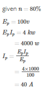
Given:
Secondary voltage, V2 = 2000 V
Secondary current, I2 = 200 V/20 kVA = 10 A
Number of turns in secondary, N2 = 66
We know that the transformer is an ideal transformer, hence it can be assumed that there are no losses in the transformer.
Calculation:
We know that the voltage across the primary and secondary is the same. Hence, we can use the voltage equation to find the number of turns in the primary.
Voltage equation for an ideal transformer is V1/V2 = N1/N2
Substituting the values in the above equation, we get
V1/2000 = N1/66
V1 = 2000(N1/66)
We know that the transformer is rated for 20 kVA. Hence, we can use the power equation to find the primary current.
Power equation for an ideal transformer is V1I1 = V2I2
Substituting the values in the above equation, we get
V1I1 = 2000 x 10
I1 = (2000 x 10)/V1
Substituting the value of V1, we get
I1 = (2000 x 10)/(2000(N1/66))
Simplifying the above equation, we get
I1 = 660/N1
We know that the transformer is rated for 20 kVA. Hence, we can use the apparent power equation to find the primary current.
Apparent power equation for an ideal transformer is V1I1 = V2I2
Substituting the values in the above equation, we get
V1I1 = 20 kVA
Substituting the values of V1 and I1, we get
2000(N1/66) x (660/N1) = 20 kVA
Simplifying the above equation, we get
N1 = 660
Hence, the number of primary turns is 660.
The 3-phase induction motor with rotor circuit open will- a)run normally
- b)get overheated
- c)not run
- d)make noise.
Correct answer is 'A'. Can you explain this answer?
The 3-phase induction motor with rotor circuit open will
a)
run normally
b)
get overheated
c)
not run
d)
make noise.
| | Niharika Basu answered |
Explanation:
When the rotor circuit of a 3-phase induction motor is open, it means that the rotor coils are disconnected from each other and from the external circuit. In this condition, the rotor cannot develop any torque and it behaves like a squirrel cage rotor. However, the stator winding is still energized and it produces a rotating magnetic field that cuts across the rotor bars. This induces currents in the rotor bars and produces a magnetic field that interacts with the stator field. As a result, the rotor experiences a torque that tends to rotate it in the same direction as the stator field.
Therefore, the correct answer is option A, the 3-phase induction motor with rotor circuit open will run normally. However, there are some important points to consider:
- The motor will not develop any useful torque because the rotor is not connected to any load. Therefore, the motor will run at a very high speed (almost synchronous speed) and it may not be able to start from rest because it has no starting torque.
- The motor will draw a very small current from the supply because the rotor impedance is very high due to the open circuit. Therefore, the motor will consume a very small amount of power and it will not get overheated.
- The motor may produce some noise because the rotor bars are not tightly coupled to the rotor core and they may vibrate or resonate at some frequencies. However, the noise level will be very low compared to a normal running motor.
Conclusion:
In summary, the 3-phase induction motor with rotor circuit open will run normally but it will not develop any useful torque, it will consume a very small amount of power, and it may produce some noise. This condition is not desirable for practical applications, but it may occur accidentally due to a fault in the rotor circuit or during some maintenance operations.
A d.c. series motor is accidentally connected to single phase supply. The torque produced will be- a)of zero average value
- b)pulsating and unidirectional
- c)oscillating
- d)steady and unidirectional
Correct answer is option 'B'. Can you explain this answer?
A d.c. series motor is accidentally connected to single phase supply. The torque produced will be
a)
of zero average value
b)
pulsating and unidirectional
c)
oscillating
d)
steady and unidirectional
| | Aman Datta answered |
Explanation:
When a d.c. series motor is accidentally connected to a single-phase supply, the torque produced will be pulsating and unidirectional. This is due to the following reasons:
1. Unidirectional torque: The d.c. series motor is designed to operate on a d.c. supply, which provides a constant unidirectional torque. However, when it is connected to a single-phase supply, the flux in the motor windings pulsates due to the alternating nature of the supply voltage. This causes the torque to also pulsate in the same manner.
2. Pulsating torque: The torque produced by the motor is directly proportional to the flux in the motor windings. As the flux pulsates due to the single-phase supply, the torque also pulsates with the same frequency. This results in a pulsating torque output from the motor.
3. No average value: The pulsating torque produced by the motor has no average value over a complete cycle. This is because the torque alternates between positive and negative values, resulting in a net torque of zero over a complete cycle.
Therefore, the torque produced by a d.c. series motor when accidentally connected to a single-phase supply is pulsating and unidirectional, with no average value over a complete cycle.
A transformer has full-load copper loss of 4000 W. The copper loss at half full- load will be .........- a)100 W
- b)200 W
- c)400 W
- d)none of the above
Correct answer is 'A'. Can you explain this answer?
A transformer has full-load copper loss of 4000 W. The copper loss at half full- load will be .........
a)
100 W
b)
200 W
c)
400 W
d)
none of the above
| | Preety Kumari answered |
Ans will be D. half load cu loss=f.l cu loss×(1/2)^2 so, h.l cu loss= 4000×1/4=1000w Btw options given r wrng... one more 0 will be add on three options
The rotor of an induction motor never runs at synchronous speed, because then the relativespeed between the rotating flux and rotor will be- a)maximum and hence, torque will b emaximum
- b)maximum and hence, torque will be zero
- c)zero and hence, torque will be maximum
- d)zero and hence, torque will be zero.
Correct answer is option 'D'. Can you explain this answer?
The rotor of an induction motor never runs at synchronous speed, because then the relativespeed between the rotating flux and rotor will be
a)
maximum and hence, torque will b emaximum
b)
maximum and hence, torque will be zero
c)
zero and hence, torque will be maximum
d)
zero and hence, torque will be zero.
 | Baishali Bajaj answered |
An induction motor always runs at a speed less than synchronous speed because the rotating magnetic field which is produced in the stator will generate flux in the rotor which will make the rotor to rotate, but due to the lagging of flux current in the rotor with flux current in the stator, the rotor will never reach .
In induction motor, greater the number of poles- a) Lesser the speed
- b) Greater the speed
- c) Lesser the frequency
- d) All of these
Correct answer is option 'A'. Can you explain this answer?
In induction motor, greater the number of poles
a)
Lesser the speed
b)
Greater the speed
c)
Lesser the frequency
d)
All of these
 | Shivam Sharma answered |
The main thing to understand is that increasing the number of poles reduces the motor's synchronous speed. A 2 pole motor on 60 hz power has a synchronous speed of 3,600 rpm. For an induction motor, that will typically drop by a “slip” percentage, typically about 4% to 3,450 rpm.
A wound rotor motor is mainly used in applications where ..............- a)low starting torque is required
- b)speed control is required
- c)less costly motor is not required
- d)high rotor resistance is required duringrunning
Correct answer is 'B'. Can you explain this answer?
A wound rotor motor is mainly used in applications where ..............
a)
low starting torque is required
b)
speed control is required
c)
less costly motor is not required
d)
high rotor resistance is required duringrunning
 | Swara Dasgupta answered |
A wound-rotor motor is used for constant-speed applications requiring a heavier starting torque than is obtain able with the squirrel-cage type. With a high-inertia load a standard cage induction motor may suffer rotor damage on starting due to the power dissipated by the rotor. With the wound rotor motor, the secondary resistors can be selected to provide the optimum torque curves and they can be sized to withstand the load energy without failure.
An efficient, low cost, simple speed control scheme is presented for wound rotor induction motors. Both stator voltage control and rotor resistance control methods are combined together and an optimum condition is found for voltage control. A thyristor based AC regulator used for stator voltage control, works efficiently at this condition. Then the rotor resistance is controlled for the adjustable speed requirements. A full speed control range has achieved, i.e. about zero to the rated speed. The motor operates satisfactorily even at very low torque and low speed conditions.
The efficiency of a power transformer is around- a)50%.
- b)60%.
- c)80%.
- d)95%.
Correct answer is option 'D'. Can you explain this answer?
The efficiency of a power transformer is around
a)
50%.
b)
60%.
c)
80%.
d)
95%.
| | Prasad Verma answered |
Efficiency of Power Transformer
The efficiency of a power transformer is an important parameter that determines the effectiveness of the transformer in transferring electrical energy from one circuit to another. It is defined as the ratio of output power to input power.
Efficiency Formula:
Efficiency = Output Power / Input Power
In practical power transformers, some power loss occurs due to various factors like core loss, copper loss, and stray loss. The efficiency of a transformer depends on the magnitude and type of these losses.
Typical Efficiency of Power Transformer
The efficiency of a power transformer depends on its size, voltage rating, and load conditions. Generally, the efficiency of a power transformer is around 95% or higher for large transformers, whereas smaller transformers may have efficiencies in the range of 80-90%.
Factors Affecting Transformer Efficiency
1. Core Losses: These are losses that occur in the transformer core due to magnetization and demagnetization of the core material. These losses depend on the frequency and magnitude of the applied voltage.
2. Copper Losses: These are losses that occur due to the resistance of the transformer windings. These losses depend on the current flowing through the transformer windings.
3. Stray Losses: These are losses that occur due to leakage flux, eddy currents, and hysteresis losses in the transformer core and windings.
Conclusion
In conclusion, the efficiency of a power transformer is an important parameter that determines the effectiveness of the transformer in transferring electrical energy from one circuit to another. The efficiency of a transformer depends on its size, voltage rating, and load conditions. Generally, the efficiency of a power transformer is around 95% or higher for large transformers, whereas smaller transformers may have efficiencies in the range of 80-90%.
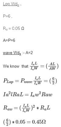
Wave winding is employed in a dc machine of- a)high current and low voltage rating.
- b)low current and high voltage rating
- c)high current and high voltage rating
- d)low current and low voltage rating
Correct answer is option 'B'. Can you explain this answer?
Wave winding is employed in a dc machine of
a)
high current and low voltage rating.
b)
low current and high voltage rating
c)
high current and high voltage rating
d)
low current and low voltage rating
| | Raghav Nambiar answered |
Wave Winding in DC Machine
Wave winding is a type of armature winding employed in DC machines. It is used for low current and high voltage rated machines. Let's understand the concept of wave winding in detail.
What is Wave Winding?
Wave winding is a type of armature winding in which the coils are connected end to end. The first coil is connected to the second coil, the second coil is connected to the third coil, and so on. The last coil is connected back to the first coil, forming a closed loop. The winding is arranged in such a way that the current flows in one direction through every alternate coil.
Working of Wave Winding
The wave winding is used in machines that require a high voltage output. When a current is passed through the armature winding, it generates a magnetic field. The magnetic field interacts with the stator field, and the armature starts to rotate. The output voltage of the machine is directly proportional to the number of turns in the armature winding. Therefore, to increase the output voltage, the number of turns in the armature winding must be increased.
Advantages of Wave Winding
- Wave winding is used in machines that require a high voltage output.
- It is simple to construct and requires less material.
- Wave winding reduces the resistance of the armature winding.
- The wave winding is less expensive than the lap winding.
Disadvantages of Wave Winding
- The wave winding has a lower current carrying capacity than the lap winding.
- The wave winding produces a unidirectional current, which can cause sparking at the brushes.
- It is not suitable for machines that require a high current output.
Conclusion
Wave winding is a type of armature winding used in DC machines. It is employed in machines that require a high voltage output. The wave winding has a simple construction and is less expensive than the lap winding. However, it has a lower current carrying capacity and produces a unidirectional current, which can cause sparking at the brushes.
In an induction motor, the air gap flux density is usually kept low so as to- a)improve efficiency
- b)improve power factor
- c)reduce machine cost
- d)none of the above
Correct answer is option 'A'. Can you explain this answer?
In an induction motor, the air gap flux density is usually kept low so as to
a)
improve efficiency
b)
improve power factor
c)
reduce machine cost
d)
none of the above
 | Mrinalini Sen answered |
If the air gap of an induction motor is increased, the following will happen:
The permeability of the magnetic circuit rotor-to-stator will decrease.
The magnetizing inductance of he motor thus decreases.
The magnetizing current will increase. This will cause a poorer power factor at all loads.
The magnetic flux in the air gap will decrease and leakage fluxes will increase. This will cause a reduction in the maximum available torque.
In summary, the maximum available torque will decrease, power factor will worsen and the motor will run with increased slip.
so it is usually kept low so as to improve efficency.
so it is usually kept low so as to improve efficency.
In Figure, the primary will see an impedance of .......
- a)20W
- b)100W
- c)1.25W
- d)none of the above
Correct answer is option 'B'. Can you explain this answer?
In Figure, the primary will see an impedance of .......
a)
20W
b)
100W
c)
1.25W
d)
none of the above
 | Hashim Abbas answered |
Use impedance transformationWhen 4 ohm resistance transfered to primary it will become 4x(5/1)^2= 4x25=10p
The armature MMF waveform of a dc machine is- a)Pulsating
- b)Rectangular
- c)Triangular
- d)Sinusoidal
Correct answer is option 'C'. Can you explain this answer?
The armature MMF waveform of a dc machine is
a)
Pulsating
b)
Rectangular
c)
Triangular
d)
Sinusoidal
| | Rajeev Menon answered |
Distorted triangular waveform shape is that of flux distribution under poles, which is due to the armature reaction. Explanation: It is cross magnetizing in nature which happens due to interaction between stator and field mmf.
Which part will surely tell that given motor is DC motor and not an AC type?- a)Winding
- b)Shaft
- c)Commutator
- d)Stator
Correct answer is option 'C'. Can you explain this answer?
Which part will surely tell that given motor is DC motor and not an AC type?
a)
Winding
b)
Shaft
c)
Commutator
d)
Stator
| | Prisha Iyer answered |
All other parts except brushes and commutator are same in AC machine when outer looks are only taken in consideration. Commutator is used only in DC machine for providing mechanical rectification and not in AC machine.
The frequency of rotor currents at standstill is equal to- a)zero
- b)2f
- c)f
- d)sf
Correct answer is option 'C'. Can you explain this answer?
The frequency of rotor currents at standstill is equal to
a)
zero
b)
2f
c)
f
d)
sf
| | Shivam Sharma answered |
When the motor is stationary,rotor conductors are being cut by rotating flux at synchronous speed.therefore,the frequency of rotor current(or emf)is the same of supply frequency.but when the rotor starts revolving,the rate at which the rotor conductors are being cut by the rotating flux depends upon the relative speed between the rotor and the stator revolving magnetic field , called the slip speed.
Which type of motors are preferred in lifts?- a)DC series motors.
- b)DC shunt motors.
- c)DC compound motors.
- d)None of the above.
Correct answer is option 'C'. Can you explain this answer?
Which type of motors are preferred in lifts?
a)
DC series motors.
b)
DC shunt motors.
c)
DC compound motors.
d)
None of the above.
| | Hrishikesh Yadav answered |
DC compound motors are preferred for lifts. Shunt type commutator motors are preferred in case of single phase installation. The latest lift designs use 3-phase slip ring induction motors with variable frequency drive electronic controls. Some may also use a similar system with permanent magnet (brush less) DC Motors.
A ceiling fan of 1400 mm sweep will have motor rating of- a)10 to 15 watts
- b)50 to 70 watts
- c)120 to 180 watts
- d)250 to 500 watts.
Correct answer is option 'C'. Can you explain this answer?
A ceiling fan of 1400 mm sweep will have motor rating of
a)
10 to 15 watts
b)
50 to 70 watts
c)
120 to 180 watts
d)
250 to 500 watts.
| | Maulik Choudhury answered |
Ceiling Fan Motor Rating:
Ceiling fans are used to circulate air in a room, and the motor rating of the fan determines its efficiency and power consumption. The motor rating of a ceiling fan is measured in watts and is related to the sweep of the fan blades.
Sweep of the Fan:
The sweep of the fan is the diameter of the circle made by the rotating blades. It is measured in millimeters and determines the area over which the fan can circulate air.
Motor Rating for 1400 mm Sweep:
For a ceiling fan with a sweep of 1400 mm, the motor rating should be between 120 to 180 watts. This is because a fan with a larger sweep requires a more powerful motor to rotate the blades. The motor rating also depends on the number of blades, their length, and the angle of inclination.
Efficiency and Power Consumption:
Ceiling fans with higher motor ratings are more efficient in terms of air circulation but consume more power. Therefore, it is important to choose a ceiling fan with an appropriate motor rating that balances efficiency and power consumption.
Conclusion:
In conclusion, the motor rating of a ceiling fan with a sweep of 1400 mm should be between 120 to 180 watts. This ensures that the fan is efficient in circulating air while consuming an appropriate amount of power.
A transformer takes a current of 0.6 A ad absorbs 64 W when the primary is connected to its normalsupply of 200 V, 50 Hz, the secondary being on open-circuit. The iron loss current is ..........- a)0.2 A
- b)0.43 A
- c)1 A
- d)0.32 A
Correct answer is option 'D'. Can you explain this answer?
A transformer takes a current of 0.6 A ad absorbs 64 W when the primary is connected to its normalsupply of 200 V, 50 Hz, the secondary being on open-circuit. The iron loss current is ..........
a)
0.2 A
b)
0.43 A
c)
1 A
d)
0.32 A
| | Swara Dasgupta answered |
Given : Io = 0.6A, (No load current)
Wo=64W (No load Loss/ Iron losses)
Vo =200V, f=50Hz, Iron loss current Iw=?
We know that Iron losses(wi) = 64W = VoIoCoso
Then Coso = 64/VoIo = 64/ (200*0.6) = 0.533
Then iron loss current(Iw) = Io Coso
= 0.6*0.533
=0.32
The motor equation is given by- a)V = Eb – Ia Ra
- b)V = Eb + Ia Ra
- c)Eb = Ia Ra – V
- d)none of the above
Correct answer is option 'B'. Can you explain this answer?
The motor equation is given by
a)
V = Eb – Ia Ra
b)
V = Eb + Ia Ra
c)
Eb = Ia Ra – V
d)
none of the above
| | Aniket Shah answered |
The Motor Equation:
The motor equation is a mathematical formula used to calculate the relationship between the voltage, current, and resistance of an electric motor. It is essential in understanding how the motor operates and how to optimize its performance. The equation is given by:
V = Eb - Ia Ra
Where V is the applied voltage, Eb is the back EMF (electromotive force), Ia is the armature current, and Ra is the armature resistance.
Explanation of Option B:
Option B is the correct answer, which states that the motor equation is V = Eb - Ia Ra. This equation is also known as the DC motor equation. The reason for this is that it is used to calculate the performance of DC motors.
The meaning of each term in the equation is as follows:
• V: The applied voltage to the motor
• Eb: The back EMF generated by the motor
• Ia: The armature current flowing through the motor
• Ra: The armature resistance
The back EMF is a crucial factor in the operation of the motor. It is the voltage generated in the armature winding of a motor when it rotates. This voltage opposes the applied voltage and reduces the current flowing through the motor. The back EMF is proportional to the speed of the motor, so as the motor speeds up, the back EMF increases, reducing the current flowing through the motor.
The armature resistance is also an important factor in the motor equation. It is the resistance of the motor's armature winding. The armature resistance determines how much current flows through the motor at a particular voltage. A motor with a low armature resistance will draw more current than a motor with a high armature resistance at the same voltage.
Conclusion:
In conclusion, the motor equation is an important equation used to calculate the performance of DC motors. It helps to understand the relationship between the voltage, current, and resistance of the motor. The correct answer to the given question is option B, which states that the motor equation is V = Eb - Ia Ra.
If the number of conductors and speed of a lap wound generator is doubled then the generated emf will be- a) Remains same
- b) Twice of the former
- c) Four times of former emf
- d) Half of the former emf
Correct answer is option 'C'. Can you explain this answer?
If the number of conductors and speed of a lap wound generator is doubled then the generated emf will be
a)
Remains same
b)
Twice of the former
c)
Four times of former emf
d)
Half of the former emf
| | Nilesh Joshi answered |
Explanation:
- A lap wound generator is a type of DC generator where the armature winding is connected in parallel with each other.
- The generated emf of a DC generator is given by the equation:
E = ΦNZ/60A
where E is the generated emf, Φ is the flux per pole, N is the speed in rpm, Z is the total number of armature conductors, and A is the number of parallel paths in the armature winding.
- Doubling the number of conductors and speed of a lap wound generator will affect the generated emf in the following ways:
Number of Conductors:
- Doubling the number of conductors, Z, will result in a proportional increase in the generated emf, E.
- This is because the number of conductors in the armature winding is directly proportional to the total flux linkage, ΦNZ, in the generator.
- Therefore, if Z is doubled, then the total flux linkage will also be doubled, resulting in a doubling of the generated emf.
Speed:
- Doubling the speed, N, will also result in a proportional increase in the generated emf, E.
- This is because the generated emf is directly proportional to the speed of the generator.
- Therefore, if N is doubled, then the generated emf will also be doubled.
Combined Effect:
- Doubling both the number of conductors and speed of a lap wound generator will result in a combined effect on the generated emf.
- The generated emf will be proportional to the product of ΦNZ and N/A.
- Therefore, if Z and N are both doubled, then the product ΦNZ will be quadrupled, while the ratio N/A will remain the same.
- As a result, the generated emf will be four times the former emf.
A capacitor start single phase induction motor will usually have a power factor of- a)unity
- b)0.8 leading
- c)0.6 leading
- d)0.6 lagging.
Correct answer is option 'D'. Can you explain this answer?
A capacitor start single phase induction motor will usually have a power factor of
a)
unity
b)
0.8 leading
c)
0.6 leading
d)
0.6 lagging.
| | Arshiya Basu answered |
Capacitor Start Single Phase Induction Motor Power Factor
A capacitor start single phase induction motor is a type of single-phase motor that uses a capacitor to provide the necessary starting torque. The capacitor is connected in series with the starting winding, which creates a phase difference between the currents in the starting and main windings. This phase difference generates a rotating magnetic field that starts the motor.
Power factor is a measure of the efficiency of an electrical system. A power factor of 1 indicates that all of the power supplied to the system is being used, while a power factor of less than 1 indicates that some of the power is being wasted. Power factor is calculated as the ratio of real power (in watts) to apparent power (in volt-amperes).
The power factor of a capacitor start single phase induction motor is determined by the design of the motor and the load it is driving. In general, the power factor of a capacitor start single phase induction motor is typically between 0.6 lagging to 0.8 leading. This means that the motor is not very efficient and is wasting some of the power supplied to it.
Reasons for Low Power Factor
There are several reasons why a capacitor start single phase induction motor may have a low power factor:
1. Motor Design: The design of the motor may not be optimized for high power factor operation.
2. Load: The load being driven by the motor may not be optimized for high power factor operation.
3. Capacitor: The capacitor used in the motor may be too small or too large for the load being driven.
4. Voltage: The voltage supplied to the motor may be too high or too low, which can affect the power factor.
Conclusion
In conclusion, a capacitor start single phase induction motor will usually have a power factor of 0.6 lagging. This is due to a combination of factors, including motor design, load, capacitor size, and voltage. To improve the power factor of a capacitor start single phase induction motor, it may be necessary to optimize the motor design, load, or capacitor size, or to adjust the voltage supplied to the motor.
A voltmeter gives 120 oscillations per minute when connected to the rotor of an induction motor. The frequency is 50 Hz. The slip of the motor is- a)2%
- b)4%
- c)5%
- d)25%
Correct answer is option 'B'. Can you explain this answer?
A voltmeter gives 120 oscillations per minute when connected to the rotor of an induction motor. The frequency is 50 Hz. The slip of the motor is
a)
2%
b)
4%
c)
5%
d)
25%
 | Rahul Chatterjee answered |
Rotor voltage frequency = 120/f = 2 Hz
Rotor voltage frequency = S x supply frequency
2 = S x 50
S = 2/50 = 0.04 = 4%
The compensating winding in a dc machine- a)is located in armature slots for compensation of the armature reaction
- b)is located on commutating poles for improving commutation
- c)is located on pole shoes for avoiding the flashover at the commutator surface.
- d)is located on pole shoes to avoid the sparking at the brushes
Correct answer is option 'C'. Can you explain this answer?
The compensating winding in a dc machine
a)
is located in armature slots for compensation of the armature reaction
b)
is located on commutating poles for improving commutation
c)
is located on pole shoes for avoiding the flashover at the commutator surface.
d)
is located on pole shoes to avoid the sparking at the brushes
| | Lakshmi Desai answered |
The compensating winding in a DC machine is an auxiliary winding that is placed on the pole shoes of the machine. It is used to compensate for the effects of armature reaction on the operation of the machine.
Armature reaction is the effect that the armature current has on the magnetic field of the machine. This can cause the magnetic field to shift and distort, which can lead to reduced machine performance and efficiency. The compensating winding is used to counteract these effects and maintain a more stable magnetic field in the machine.
Explanation:
Location of Compensating Winding: The compensating winding is located on the pole shoes of the machine.
Purpose of Compensating Winding: The main purpose of the compensating winding is to avoid the flashover at the commutator surface.
Effects of Armature Reaction: Armature reaction can cause a number of negative effects on the operation of the machine, including:
- Reduced machine performance and efficiency
- Increased heating of the machine
- Commutation problems, including sparking and brush wear
Benefits of Compensating Winding: The compensating winding helps to counteract these negative effects and provides a number of benefits, including:
- Improved machine performance and efficiency
- Reduced heating of the machine
- Improved commutation, including reduced sparking and brush wear
Conclusion: In conclusion, the compensating winding in a DC machine is an important component that helps to counteract the negative effects of armature reaction and maintain a more stable magnetic field in the machine. It is located on the pole shoes of the machine and is primarily used to avoid the flashover at the commutator surface.
In a double squirrel cage induction motor, the outer cage winding has ................- a)high inductance
- b)low resistance
- c)high resistance
- d)none of the above
Correct answer is option 'C'. Can you explain this answer?
In a double squirrel cage induction motor, the outer cage winding has ................
a)
high inductance
b)
low resistance
c)
high resistance
d)
none of the above
| | Sagarika Patel answered |
The outer cage winding carries most of the starting current which offer low impedance to the flow of current. The high resistance outer cage winding, therefore, develops a high starting torque.
A reluctance motor runs at- a)synchronous speed
- b)slightly less than synchronous speed
- c)half the synchronous speed
- d)above synchronous speed
Correct answer is option 'A'. Can you explain this answer?
A reluctance motor runs at
a)
synchronous speed
b)
slightly less than synchronous speed
c)
half the synchronous speed
d)
above synchronous speed
| | Tanvi Shah answered |
The rotor operates at synchronous speeds without current-conducting parts. Rotor losses are minimal compared to those of an induction motor.
Once started at synchronous speed, the motor can operate with sinusoidal voltage. Speed control requires a variable-frequency drive.
How are transformers generally cooled for installations rated at less than 5 kVA ?- a)Oil cooled
- b)air cooled
- c)water cooled
- d)none of the above
Correct answer is option 'B'. Can you explain this answer?
How are transformers generally cooled for installations rated at less than 5 kVA ?
a)
Oil cooled
b)
air cooled
c)
water cooled
d)
none of the above
| | Baishali Bajaj answered |
Oil acts as a best coolant material, for transformer cooling. Due to its high efficiency as a coolant it is most widely used in transformers. Not only same but Oil with suitable properties can be used for various power transformers according to their ratings. OPTION (A) IS CORRECT.
The condition for the electrical symmetry of the circuit is that- a)h12 = h21
- b)AD – BC = 1
- c)Z12 = Z21
- d)A = D
Correct answer is option 'D'. Can you explain this answer?
The condition for the electrical symmetry of the circuit is that
a)
h12 = h21
b)
AD – BC = 1
c)
Z12 = Z21
d)
A = D
| | Neha Choudhury answered |
Two port Network Parameter equations:
Port variables:
(Dependent): V1, i1
(Independent): V2, i2
Equations:
V1 = AV2 + B(–i2)
i1 = CV2 + D(–i2)
Condition of reciprocity: AD – BC = 1
Condition of symmetry: A = D
The frequency of the induced emf in an induction motor is- a)Greater than the supply frequency
- b)Same as the supply frequency
- c)Lesser as the supply frequency
- d)None of these
Correct answer is option 'C'. Can you explain this answer?
The frequency of the induced emf in an induction motor is
a)
Greater than the supply frequency
b)
Same as the supply frequency
c)
Lesser as the supply frequency
d)
None of these
| | Anjana Singh answered |
Explanation:
The frequency of the induced emf in an induction motor depends on the relative speed between the rotating magnetic field produced by the stator and the rotor. Here's a detailed explanation:
1. Supply Frequency: The supply frequency is the frequency of the alternating current (AC) power source that is connected to the motor.
2. Rotating Magnetic Field: The stator of the induction motor produces a rotating magnetic field with a frequency equal to the supply frequency.
3. Slip: The relative speed between the rotating magnetic field and the rotor is known as slip. Slip is determined by the load on the motor and the design of the motor.
4. Induced Emf: The rotor of the induction motor is made of conducting bars. When the rotating magnetic field cuts across these bars, an emf is induced in them. This induced emf is known as the rotor emf.
5. Frequency of Induced Emf: The frequency of the induced emf in the rotor is directly proportional to the slip.
6. Slip and Frequency: As the slip increases, the frequency of the induced emf decreases. This is because the rotor is trying to "catch up" with the rotating magnetic field, resulting in a smaller relative speed between them.
7. Lower Frequency: Therefore, the frequency of the induced emf in the rotor is always lower than the supply frequency. It is important to note that the magnitude of the induced emf can be higher or lower depending on the slip and other factors.
Conclusion: The frequency of the induced emf in an induction motor is always less than the supply frequency. Therefore, the correct answer is C: Lesser than the supply frequency.
Which of the following motors has the largest starting torque ?- a)shaded - pole motor
- b)repulsion motor
- c)split - phase motor
- d)capacitor -start motor
Correct answer is option 'D'. Can you explain this answer?
Which of the following motors has the largest starting torque ?
a)
shaded - pole motor
b)
repulsion motor
c)
split - phase motor
d)
capacitor -start motor
| | Isha Singh answered |
A Capacitor Start Motors is a single phase Induction Motor that employs a capacitor in the auxiliary winding circuit to produce a greater phase difference between the current in the main and the auxiliary windings. Due to greater phase difference capacitor Start motors have very high starting torque for a single-phase AC motor.
The best suited motor to drive 1/4 h.p fan in ahospital ward would be ........... motor.- a)shaded-pole
- b)single -phase series
- c)capacitor -run
- d)hysteresis
Correct answer is 'C'. Can you explain this answer?
The best suited motor to drive 1/4 h.p fan in ahospital ward would be ........... motor.
a)
shaded-pole
b)
single -phase series
c)
capacitor -run
d)
hysteresis
| | Abhishek Chauhan answered |
Explanation:
A 1/4 h.p fan is a small motor, typically used in a hospital ward to provide air circulation. The best suited motor to drive this fan would be a capacitor-run motor. Here's why:
1. Shaded-pole motor: This type of motor is low cost and simple, but it has low efficiency and poor starting torque. It is not suitable for driving a fan in a hospital ward, where reliability and performance are critical.
2. Single-phase series motor: This type of motor has high starting torque, but it is not suitable for continuous duty applications like driving a fan. It is also less efficient than other motor types.
3. Capacitor-run motor: This type of motor has high efficiency and good starting torque, making it ideal for driving a fan. It is also reliable and has a long lifespan. The capacitor provides a phase shift, which creates a rotating magnetic field that drives the motor.
4. Hysteresis motor: This type of motor is also efficient and reliable, but it has low starting torque and is more expensive than a capacitor-run motor. It is not necessary for driving a small fan in a hospital ward.
Conclusion:
In summary, the best suited motor to drive a 1/4 h.p fan in a hospital ward is a capacitor-run motor. It provides high efficiency, good starting torque, and reliability, making it ideal for this application.
The all-day efficiency of a transformer is also called its- a)energy efficiency
- b)power efficiency
- c)current efficiency
- d)none of the above
Correct answer is option 'A'. Can you explain this answer?
The all-day efficiency of a transformer is also called its
a)
energy efficiency
b)
power efficiency
c)
current efficiency
d)
none of the above
| | Aman Jain answered |
**Answer:**
The all-day efficiency of a transformer refers to the energy efficiency of the transformer over an extended period of time. It is an important parameter to assess the performance and effectiveness of a transformer. The efficiency of a transformer is defined as the ratio of output power to input power.
**Energy Efficiency:**
Energy efficiency is the ratio of useful output energy to the input energy. In the case of a transformer, the useful output energy is the energy delivered to the load, and the input energy is the energy supplied to the transformer from the source. Therefore, the energy efficiency of a transformer is a measure of how effectively it converts the input energy into useful output energy.
**Power Efficiency:**
Power efficiency is the ratio of useful output power to the input power. While power efficiency is related to energy efficiency, it specifically focuses on the power aspect of the transformer. It indicates how efficiently the transformer converts the input power into useful output power.
**Current Efficiency:**
Current efficiency is not the correct term to describe the all-day efficiency of a transformer. Current efficiency is a term used in electroplating and refers to the ratio of the actual current used in the process to the theoretical current required for the same process. It is not applicable to transformers.
**Conclusion:**
The correct term to describe the all-day efficiency of a transformer is energy efficiency. It quantifies the ability of the transformer to convert input energy into useful output energy. By improving the energy efficiency of a transformer, we can reduce energy losses and improve overall system performance.
A motor converts- a)Mechanical energy into electrical energy
- b)Chemical energy into electrical energy
- c)Electrical energy into Mechanical energy
- d)Electrical energy into chemical energy
Correct answer is option 'C'. Can you explain this answer?
A motor converts
a)
Mechanical energy into electrical energy
b)
Chemical energy into electrical energy
c)
Electrical energy into Mechanical energy
d)
Electrical energy into chemical energy
 | Shruthi Vepoor answered |
C.....always motor input is electrical energy in order to give excitation
The all-day efficiency of a distribution transformer is .......... the commercial efficiency- a)the same as
- b)more than
- c)less than
- d)none of the above
Correct answer is 'A'. Can you explain this answer?
The all-day efficiency of a distribution transformer is .......... the commercial efficiency
a)
the same as
b)
more than
c)
less than
d)
none of the above
| | Debanshi Nair answered |
Efficiency of a Distribution Transformer
Definition of Efficiency:
Efficiency is the ratio of output power to input power.
Commercial Efficiency:
Commercial Efficiency is the ratio of output power to input power, where output power is the power delivered to the load and input power is the power supplied to the transformer. It is also known as load efficiency.
All-Day Efficiency:
All-Day Efficiency is the ratio of energy output to energy input, where energy output is the energy delivered to the load and energy input is the energy supplied to the transformer over a 24-hour period.
Relation between Commercial and All-Day Efficiency:
The all-day efficiency of a distribution transformer is the same as the commercial efficiency. This is because the losses in a transformer are constant over a 24-hour period. Hence, the ratio of output power to input power remains the same for both commercial and all-day efficiency.
Conclusion:
Therefore, the correct answer is option A, the all-day efficiency of a distribution transformer is the same as the commercial efficiency.
The type of dc generator used for arc welding purposes is a- a)series generator
- b)shunt generator
- c)cumulatively compounded generator
- d)differentially compounded generator
Correct answer is option 'D'. Can you explain this answer?
The type of dc generator used for arc welding purposes is a
a)
series generator
b)
shunt generator
c)
cumulatively compounded generator
d)
differentially compounded generator
 | Bijoy Kapoor answered |
Differential compound generator is used in arc welding. To create an electric arc can be used both AC and DC voltage source, but will be stable DC voltage arc. This type of DC generators are generally more expensive than self-excited DC generators because of their requirement of separate excitation source.
A capacitor-start, capacitor -run motor has.............- a)low power factor
- b)high power factor
- c)low efficiency
- d)high starting torque
Correct answer is option 'B'. Can you explain this answer?
A capacitor-start, capacitor -run motor has.............
a)
low power factor
b)
high power factor
c)
low efficiency
d)
high starting torque
| | Samridhi Bose answered |
Capacitor-start, capacitor-run motor
A capacitor-start, capacitor-run motor is a type of single-phase induction motor that uses a capacitor to provide an initial phase shift to the stator windings. The capacitor is then disconnected from the circuit once the motor reaches a certain speed, and a second capacitor is used to maintain the phase shift and improve the motor's efficiency.
Power factor
The power factor of a motor is a measure of how efficiently it converts electrical power into mechanical power. A low power factor indicates that the motor is not using the electrical power efficiently, and is therefore less efficient overall.
High power factor
A capacitor-start, capacitor-run motor has a high power factor because the capacitor provides an initial phase shift that helps to improve the efficiency of the motor. By using two capacitors, the motor is able to maintain this phase shift and operate at a high power factor throughout its operating range.
Starting torque
In addition to its high power factor, a capacitor-start, capacitor-run motor also has a high starting torque. This is because the initial phase shift provided by the capacitor helps to create a rotating magnetic field that produces the necessary torque to start the motor.
Efficiency
Overall, a capacitor-start, capacitor-run motor is more efficient than other types of single-phase induction motors, such as split-phase and shaded-pole motors. This is due to its high power factor and ability to maintain the phase shift throughout its operating range.
Chapter doubts & questions for Electrical Machines - RRB JE for Electrical Engineering 2026 is part of Electrical Engineering (EE) exam preparation. The chapters have been prepared according to the Electrical Engineering (EE) exam syllabus. The Chapter doubts & questions, notes, tests & MCQs are made for Electrical Engineering (EE) 2026 Exam. Find important definitions, questions, notes, meanings, examples, exercises, MCQs and online tests here.
Chapter doubts & questions of Electrical Machines - RRB JE for Electrical Engineering in English & Hindi are available as part of Electrical Engineering (EE) exam. Download more important topics, notes, lectures and mock test series for Electrical Engineering (EE) Exam by signing up for free.
RRB JE for Electrical Engineering23 videos|84 docs|32 tests |