


All Exams > Electrical Engineering (EE) > Electrical Machines for Electrical Engg. > All Questions
All questions of Single-Phase Transformers for Electrical Engineering (EE) Exam
A 10 kVA, 400/200 V, 1-phase transformer with 2% resistance and 2% leakage reactance. It draws steady short circuit current at angle of- a)45°
- b)75°
- c)135°
- d)0°
Correct answer is option 'A'. Can you explain this answer?
A 10 kVA, 400/200 V, 1-phase transformer with 2% resistance and 2% leakage reactance. It draws steady short circuit current at angle of
a)
45°
b)
75°
c)
135°
d)
0°
| | Mihir Khanna answered |
Given Data:
- Transformer Rating: 10 kVA, 400/200 V, 1-phase
- Resistance (R): 2%
- Leakage Reactance (X): 2%
Steps to Calculate the Angle of Short-Circuit Current:
- Determine the Impedance: The impedance ZZZ of the transformer can be calculated using the given percentage values for resistance and reactance:Z=R+jXZ = R + jXZ=R+jXwhere RRR and XXX are the resistance and reactance.Given:R=2% of Z (assuming Z as base impedance, Z = 100)R = 2\% \text{ of } Z \text{ (assuming Z as base impedance, Z = 100)}R=2% of Z (assuming Z as base impedance, Z = 100) X=2% of Z (assuming Z as base impedance, Z = 100)X = 2\% \text{ of } Z \text{ (assuming Z as base impedance, Z = 100)}X=2% of Z (assuming Z as base impedance, Z = 100)
- Calculate the Impedance Angle: The impedance angle θ\thetaθ is determined by:θ=tan−1(XR)\theta = \tan^{-1} \left(\frac{X}{R}\right)θ=tan−1(RX)Substituting R=2R = 2R=2 and X=2X = 2X=2:θ=tan−1(22)=tan−1(1)=45°\theta = \tan^{-1} \left(\frac{2}{2}\right) = \tan^{-1}(1) = 45°θ=tan−1(22)=tan−1(1)=45°
Angle of the Short-Circuit Current:
The angle of the short-circuit current is equal to the angle of the impedance because the current in a short-circuit condition is essentially the same as the impedance angle.
Conclusion:
The steady short-circuit current draws at an angle of:
1. 45°

Which if the conditions is must be fulfilled for a satisfactory parallel operation of transformers?- a)Same voltage ratio
- b)Leakage impedances should be inversely proportional to kVA of the transformer
- c)Same pu impedance
- d)Correct polarity
Correct answer is option 'D'. Can you explain this answer?
Which if the conditions is must be fulfilled for a satisfactory parallel operation of transformers?
a)
Same voltage ratio
b)
Leakage impedances should be inversely proportional to kVA of the transformer
c)
Same pu impedance
d)
Correct polarity
| | Om Saini answered |
out of all, polarity must be correct for the connected transformers.
A. Positive sequence components – 5th harmonic component
B. Negative sequence components – 7th harmonic component
C. Zero sequence components – 3rd harmonic component
Above are the matching made for the harmonics and the associated harmonic component, then the correct marking is- a)A,B,C
- b)C
- c)A,B
- d)B,C
Correct answer is option 'B'. Can you explain this answer?
A. Positive sequence components – 5th harmonic component
B. Negative sequence components – 7th harmonic component
C. Zero sequence components – 3rd harmonic component
Above are the matching made for the harmonics and the associated harmonic component, then the correct marking is
B. Negative sequence components – 7th harmonic component
C. Zero sequence components – 3rd harmonic component
Above are the matching made for the harmonics and the associated harmonic component, then the correct marking is
a)
A,B,C
b)
C
c)
A,B
d)
B,C
| | Sanya Agarwal answered |
3m-1 phases are displaced 120° in opposite and (3m+1) in the same direction as the fundamental. Here ‘m’ is even integer. So 5th harmonic is in negative sequence and 7th harmonic component in positive sequence.
While conducting open circuit test and short circuit test on a transformer, status of low-voltage and high-voltage windings will be such that in- a)OC test – l.v. open, SC test-h.v. short-circuited
- b)OC test – h.v. open, SC test-l.v. short-circuited
- c)OC test – l.v. open, SC test-l.v. short-circuited
- d)OC test – h.v. open, SC test-h.v. short-circuited
Correct answer is option 'A'. Can you explain this answer?
While conducting open circuit test and short circuit test on a transformer, status of low-voltage and high-voltage windings will be such that in
a)
OC test – l.v. open, SC test-h.v. short-circuited
b)
OC test – h.v. open, SC test-l.v. short-circuited
c)
OC test – l.v. open, SC test-l.v. short-circuited
d)
OC test – h.v. open, SC test-h.v. short-circuited
| | Harshitha Pillai answered |
For transformer testing:
- Open Circuit (OC) Test:
- This test is used to determine the core losses and no-load characteristics of the transformer. In this test, the high-voltage (HV) winding is energized, and the low-voltage (LV) winding is kept open.
- Short Circuit (SC) Test:
- This test is used to measure the copper losses and the impedance of the transformer. In this test, the low-voltage (LV) winding is short-circuited, and the high-voltage (HV) winding is energized.
So, the correct configuration is:
2. OC test – l.v. open, SC test – h.v. short-circuited
The efficiency of two identical transformers under load conditions can be determined by- a)Short-circuit test
- b)Back-to-back test
- c)Open circuit test
- d)Any of the above
Correct answer is option 'B'. Can you explain this answer?
The efficiency of two identical transformers under load conditions can be determined by
a)
Short-circuit test
b)
Back-to-back test
c)
Open circuit test
d)
Any of the above
| | Ritika Sarkar answered |
Voltage regulation is the change in secondary voltage with secondary rated voltage.
Two single phase transformers A and B are operating in parallel having same impedance. But the x/r ratio of them are not equal. Then total kVA output of the output will be- a)less than sum of kVA of A and B
- b)more than sum of kVA of A and B
- c)equal to sum of kVA of A and B
- d)any of the mentioned
Correct answer is option 'A'. Can you explain this answer?
Two single phase transformers A and B are operating in parallel having same impedance. But the x/r ratio of them are not equal. Then total kVA output of the output will be
a)
less than sum of kVA of A and B
b)
more than sum of kVA of A and B
c)
equal to sum of kVA of A and B
d)
any of the mentioned
| | Vaibhav Mukherjee answered |
As the leakage reactances are not same for both the transformers, then Ia < I2 and Ib < I/2.
So the kVA will also be less than sum of individual A and B.
So the kVA will also be less than sum of individual A and B.
For given applied voltage, with the increase in frequency of the applied voltage- a)eddy current loss will decrease
- b)eddy current loss will increase
- c)eddy current loss will remain unchanged
- d)none of the above
Correct answer is option 'C'. Can you explain this answer?
For given applied voltage, with the increase in frequency of the applied voltage
a)
eddy current loss will decrease
b)
eddy current loss will increase
c)
eddy current loss will remain unchanged
d)
none of the above
| | Partho Saha answered |
Explanation:
Eddy currents are produced in a conductor when it is exposed to a changing magnetic field. These currents flow in closed loops and generate heat, which can cause energy losses. The amount of eddy current loss depends on various factors such as the material properties of the conductor, the frequency of the applied voltage, and the shape of the conductor.
Effect of frequency on eddy current loss:
When a conductor is exposed to an alternating voltage, the frequency of the voltage determines the rate at which the magnetic field changes. Therefore, the frequency of the applied voltage has a significant impact on the amount of eddy current loss in the conductor. The following points explain the effect of frequency on eddy current loss:
- At low frequencies, the magnetic field changes slowly, and eddy currents have enough time to build up and flow through the conductor. As a result, eddy current loss is high at low frequencies.
- At high frequencies, the magnetic field changes rapidly, and eddy currents do not have enough time to build up and flow through the conductor. Therefore, eddy current loss is low at high frequencies.
- At a certain frequency, called the skin depth frequency, the eddy currents are mostly confined to the surface layer of the conductor. This is because the skin depth, which is the depth at which the eddy current density has decreased to 1/e (about 37%) of its surface value, becomes smaller than the thickness of the conductor. At this frequency, the eddy current loss is minimum. The skin depth frequency depends on the material properties of the conductor and the frequency of the applied voltage.
Conclusion:
In conclusion, the eddy current loss in a conductor remains unchanged with the increase in frequency of the applied voltage, provided the skin depth frequency is not reached. Beyond the skin depth frequency, the eddy current loss decreases with an increase in frequency. Thus, the correct option is C.
While conducting testing on the single phase transformer, one of the student tries to measure the resistance by putting an ammeter across one terminal of primary and other to secondary, the reading obtained will be- a)infinite
- b)zero
- c)finite
- d)negative finite
Correct answer is option 'A'. Can you explain this answer?
While conducting testing on the single phase transformer, one of the student tries to measure the resistance by putting an ammeter across one terminal of primary and other to secondary, the reading obtained will be
a)
infinite
b)
zero
c)
finite
d)
negative finite
 | Sagarika Patel answered |
As the primary and secondary are physically isolated, the impedance will be infinite for not electrically connected circuit.
A 200/400 V single phase transformer has leakage impedance z= r+jx. Then we can expect magnitude of load pf of ____ at zero voltage regulation.- a)x/r leading
- b)x/r lagging
- c)r/x leading
- d)r/x lagging
Correct answer is option 'A'. Can you explain this answer?
A 200/400 V single phase transformer has leakage impedance z= r+jx. Then we can expect magnitude of load pf of ____ at zero voltage regulation.
a)
x/r leading
b)
x/r lagging
c)
r/x leading
d)
r/x lagging
| | Sagarika Patel answered |
ZVR occurs at the leading pf of load at x/r.
The size of a transformer core will depend on- a)frequency
- b)area of the core
- c)flux density of the core material
- d)(A) and (B) both
Correct answer is option 'D'. Can you explain this answer?
The size of a transformer core will depend on
a)
frequency
b)
area of the core
c)
flux density of the core material
d)
(A) and (B) both
 | Shyamala M answered |
For a given transformer rating, as the frequency increases the product of window area and cross sectional area of the limb decreases; which means the iron required for the core decreases. Therefore as the frequency increases, the transformer becomes lighter and smaller in size.
The area of the window and cross sectional area of the limb are the main dimensions of a transformer, the product of which is directly proportional to the size and weight of the transformer. More the product (area), bigger and heavier is the transformer.
The area of the window and cross sectional area of the limb are the main dimensions of a transformer, the product of which is directly proportional to the size and weight of the transformer. More the product (area), bigger and heavier is the transformer.
Which of the following informations are not obtained from short-circuit test?I. Ohmic losses at rated current
II. Equivalent resistance and leakage reactance
III. Core losses
IV. Voltage regulation- a)I, II
- b)II, IV
- c)I, II, IV
- d)II, III
Correct answer is option 'D'. Can you explain this answer?
Which of the following informations are not obtained from short-circuit test?
I. Ohmic losses at rated current
II. Equivalent resistance and leakage reactance
III. Core losses
IV. Voltage regulation
II. Equivalent resistance and leakage reactance
III. Core losses
IV. Voltage regulation
a)
I, II
b)
II, IV
c)
I, II, IV
d)
II, III
| | Vibhor Goyal answered |
Core losses are found from OC test and the voltage regulation is not obtained from one single test here.
Two single phase transformers A and B are operating in parallel having different impedance and identical x/r ratio. Also impedance of A is more than that of B,then- a)Za/Zb = Sb/Sa
- b)Za/Zb = Sa/Sb
- c)Za/Zb = 1
- d)Za/Zb = (Sb/Sa)2
Correct answer is option 'A'. Can you explain this answer?
Two single phase transformers A and B are operating in parallel having different impedance and identical x/r ratio. Also impedance of A is more than that of B,then
a)
Za/Zb = Sb/Sa
b)
Za/Zb = Sa/Sb
c)
Za/Zb = 1
d)
Za/Zb = (Sb/Sa)2
| | Hridoy Chakraborty answered |
Leakage impedance in ‘ohms’ are inverse ratio of their respective kVA ratings.
If a 2200/220 V, 60 Hz single phase transformer has primary and secondary resistance of 100 Ω and 10 Ω, respectively. Then the value of equivalent resistance of the transformer referred to the primary side and secondary side are- a)1100 Ω and 20 Ω respectively
- b)20 Ω and 1100 Ω respectively
- c)1100 Ω and 11 Ω respectively
- d)11 Ω and 1100 Ω respectively
Correct answer is option 'C'. Can you explain this answer?
If a 2200/220 V, 60 Hz single phase transformer has primary and secondary resistance of 100 Ω and 10 Ω, respectively. Then the value of equivalent resistance of the transformer referred to the primary side and secondary side are
a)
1100 Ω and 20 Ω respectively
b)
20 Ω and 1100 Ω respectively
c)
1100 Ω and 11 Ω respectively
d)
11 Ω and 1100 Ω respectively
 | EduRev GATE answered |
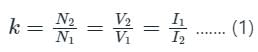
Concept:
In a transformer, the turns ratio is given by
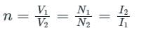
Where V1 is the primary voltage
V2 is the secondary voltage
N1 is the primary turns
N2 is the secondary turns
I1 is the primary current
I2 is the secondary current
The equivalent resistance of the transformer referred to the primary side = R1 + n2R2
The equivalent resistance of the transformer referred to the secondary side = R2 + R1/n2
Calculation:
Given that, primary voltage (V1) = 2200 V
Secondary voltage (V2) = 220 V
Primary resistance (R1) =100 Ω
Secondary resistance (R2) = 10 Ω
Turns ratio = 2200/220 = 10
∴ Equivalent resistance of the transformer referred to the primary side
=> R1 + n2R2 = [100 + (10)2 × 10] = 1100 Ω
∴ Equivalent resistance of the transformer referred to the secondary side
=> R2 + R1/n2 = [10 + 100/(10)2] = 11 Ω
Which of the following mentioned losses occur in a transformer?- a)Hysteresis losses; Eddy current losses; Dielectric losses; Stray load losses
- b)Hysteresis losses; Eddy current losses;
- c)Dielectric losses; Stray load losses
- d)Hysteresis losses; Eddy current losses; Stray load losses
Correct answer is option 'A'. Can you explain this answer?
Which of the following mentioned losses occur in a transformer?
a)
Hysteresis losses; Eddy current losses; Dielectric losses; Stray load losses
b)
Hysteresis losses; Eddy current losses;
c)
Dielectric losses; Stray load losses
d)
Hysteresis losses; Eddy current losses; Stray load losses
| | EduRev GATE answered |
Hysteresis losses-due to magnetic material; Eddy current losses-on the core area; Dielectric losses- due to insulation material; Stray load losses- due to leakage through the parts of the transformer.
While estimating voltage regulation of a transformer, keeping- a)primary voltage constant
- b)secondary voltage constant
- c)voltage changes constant at primary
- d)all of the mentioned
Correct answer is option 'A'. Can you explain this answer?
While estimating voltage regulation of a transformer, keeping
a)
primary voltage constant
b)
secondary voltage constant
c)
voltage changes constant at primary
d)
all of the mentioned
 | Swara Dasgupta answered |
V.R. is calculated keeping the primary constant because then the core flux will change and the change of secondary voltage can not be fixed.
Operating transformers in parallel gives the advantage of- a)reliable loading
- b)increased capacity of power system
- c)reducing the capacity of substation
- d)all of the mentioned
Correct answer is option 'D'. Can you explain this answer?
Operating transformers in parallel gives the advantage of
a)
reliable loading
b)
increased capacity of power system
c)
reducing the capacity of substation
d)
all of the mentioned
 | Rahul Chatterjee answered |
All are advantages of having parallel connection of transformers.
A 2000/1000/500 three winding transformer is to be used as auto transformer with supply of 3000 V. Two loads of 1050 kVA at 3500V,and other one at 180 kVA at 1000V. The total kVA supplied will be- a)1230 kVA
- b)1440 kVA
- c)1680 kVA
- d)1150 kVA
Correct answer is option 'A'. Can you explain this answer?
A 2000/1000/500 three winding transformer is to be used as auto transformer with supply of 3000 V. Two loads of 1050 kVA at 3500V,and other one at 180 kVA at 1000V. The total kVA supplied will be
a)
1230 kVA
b)
1440 kVA
c)
1680 kVA
d)
1150 kVA
 | Bijoy Kapoor answered |
Total kVA = 1050+180 = 1230 kVA.
The changes in volume of transformer cooling oil due to variation of atmospheric tem-perature during day and night is taken care of by which part of transformer- a)Conservator
- b)Breather
- c)Bushings
- d)Buchholz relay
Correct answer is option 'A'. Can you explain this answer?
The changes in volume of transformer cooling oil due to variation of atmospheric tem-perature during day and night is taken care of by which part of transformer
a)
Conservator
b)
Breather
c)
Bushings
d)
Buchholz relay
| | Rajesh Verma answered |
Transformer Cooling Oil and Atmospheric Temperature Changes
Transformer cooling oil is essential in maintaining the optimal temperature of a transformer. During the day and night, the atmospheric temperature changes, which can affect the volume of transformer cooling oil. The changes in volume of transformer cooling oil due to variation of atmospheric temperature during day and night is taken care of by the conservator.
Conservator
A conservator is a cylindrical metal container that connects to the transformer tank. It contains a diaphragm that separates the oil from the air, preventing air from coming into contact with the oil. The conservator acts as a reservoir for the cooling oil, allowing for the expansion and contraction of the oil due to temperature changes.
Working of Conservator
When the atmospheric temperature increases, the volume of the transformer cooling oil expands, causing the oil level in the conservator to rise. The oil flows from the transformer tank to the conservator, and the diaphragm in the conservator expands to accommodate the increased volume of oil. In contrast, when the atmospheric temperature decreases, the volume of the transformer cooling oil contracts, causing the oil level in the conservator to drop. The oil flows from the conservator to the transformer tank, and the diaphragm in the conservator contracts to accommodate the decreased volume of oil.
Conclusion
In conclusion, the changes in volume of transformer cooling oil due to variation of atmospheric temperature during day and night is taken care of by the conservator. The conservator acts as a reservoir for the cooling oil, allowing for the expansion and contraction of the oil due to temperature changes.
Part of the transformer which is most subject to damage from overheating is- a)iron core
- b)copper winding
- c)winding insulation
- d)frame or case
Correct answer is option 'C'. Can you explain this answer?
Part of the transformer which is most subject to damage from overheating is
a)
iron core
b)
copper winding
c)
winding insulation
d)
frame or case
| | Akhinapelli Sindhuja answered |
As insulation is placed over the winding,when transformer subject to overheating due to supplied a more load.the insulation may damages than winding.
The open circuit test results in finding which of the following parameters?I. core losses
II. shunt branch parameters
III. turns ratio of transformer- a)I, II, III
- b)I, II
- c)II, III
- d)I, III
Correct answer is option 'A'. Can you explain this answer?
The open circuit test results in finding which of the following parameters?
I. core losses
II. shunt branch parameters
III. turns ratio of transformer
II. shunt branch parameters
III. turns ratio of transformer
a)
I, II, III
b)
I, II
c)
II, III
d)
I, III
| | EduRev GATE answered |
OC test gives the shunt branch parameters as well as the turns ratio by connecting a voltmeter at open circuited secondary terminals.
Which of the statements made here are correct regarding the transformer?I. Maximum voltage regulation occurs at the leading p.f.
II. Maximum voltage regulation occurs when load p.f. angle and impedance angle of the leakage impedance are same.
III. V.R. at zero p.f. is always zero.
IV. V.R. of a transformer may be negative at leading p.f.- a)I, III
- b)II, IV
- c)1, III
- d)I, IV, III
Correct answer is option 'B'. Can you explain this answer?
Which of the statements made here are correct regarding the transformer?
I. Maximum voltage regulation occurs at the leading p.f.
II. Maximum voltage regulation occurs when load p.f. angle and impedance angle of the leakage impedance are same.
III. V.R. at zero p.f. is always zero.
IV. V.R. of a transformer may be negative at leading p.f.
II. Maximum voltage regulation occurs when load p.f. angle and impedance angle of the leakage impedance are same.
III. V.R. at zero p.f. is always zero.
IV. V.R. of a transformer may be negative at leading p.f.
a)
I, III
b)
II, IV
c)
1, III
d)
I, IV, III
 | Engineers Adda answered |
V.R. is always negative at leading p.f. and the load p.f. angle and impedance angle of the leakage impedance should be same for maximum V.R.
If the pu impedance of a single phase transformer is 0.01+j0.05, then its regulation at p.f. of 0.8 lagging will be- a)3.8%
- b)2.2%
- c)-3.8%
- d)-2.2%
Correct answer is option 'A'. Can you explain this answer?
If the pu impedance of a single phase transformer is 0.01+j0.05, then its regulation at p.f. of 0.8 lagging will be
a)
3.8%
b)
2.2%
c)
-3.8%
d)
-2.2%
| | Divya Nair answered |
V.R. = (r(pu)*cosθ+x(pu)*sinθ)*100 % = (0.01*0.8 + 0.05*0.6)*100 = 3.8%
Mutual flux ______ at the lagging loading and it _____ at the leading power factor.- a)decreases, increases
- b)increases, increases
- c)decreases, decreases
- d)increases, decreases
Correct answer is option 'A'. Can you explain this answer?
Mutual flux ______ at the lagging loading and it _____ at the leading power factor.
a)
decreases, increases
b)
increases, increases
c)
decreases, decreases
d)
increases, decreases
 | Bayshore Academy answered |
The mutual flux falls when the transformer is working at lagging p.f. and it increases at leading p.f.
The efficiency of a 20 KVA, 2000/200 V, single phase transformer at unity pf is 98%. The total losses at this condition is?- a)408W
- b)4.08kW
- c)204W
- d)2.04kW
Correct answer is option 'A'. Can you explain this answer?
The efficiency of a 20 KVA, 2000/200 V, single phase transformer at unity pf is 98%. The total losses at this condition is?
a)
408W
b)
4.08kW
c)
204W
d)
2.04kW
| | Hridoy Chakraborty answered |
Given data:
- Power rating of the transformer (S) = 20 kVA
- Voltage rating of the transformer (V1/V2) = 2000/200 V
- Efficiency (η) = 98%
Calculating total losses:
- Efficiency (η) = Output power / Input power
- Input power = Output power / Efficiency
- Input power = 20 kVA / 0.98 = 20.41 kVA
- Input power = 20.41 kW
Calculating copper losses:
- Copper losses = Input power - Output power
- Copper losses = 20.41 kW - 20 kVA = 0.41 kW = 410 W
Calculating iron losses:
- Iron losses = Total losses - Copper losses
- Iron losses = 20.41 kW - 410 W = 20 kW
Answer:
- The total losses at this condition is 410 W. Therefore, the correct option is (a) 408 W.
A one-phase, 50 Hz, 40 kVA transformer with a ratio of 2000 V/250 V has a primary resistance of 1.15 Ω and a secondary resistance of 0.0155 Ω. Calculate total copper loss on half of the full load. - a)856.8 W
- b)214.2 W
- c)642.6 W
- d)428.4 W
Correct answer is option 'B'. Can you explain this answer?
A one-phase, 50 Hz, 40 kVA transformer with a ratio of 2000 V/250 V has a primary resistance of 1.15 Ω and a secondary resistance of 0.0155 Ω. Calculate total copper loss on half of the full load.
a)
856.8 W
b)
214.2 W
c)
642.6 W
d)
428.4 W
| | Vibhor Goyal answered |
Concept:
Consider a two winding single phase transformer as shown below,
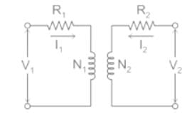
N1 = primary winding turns
N2 = secondary winding turns
V1 = primary winding voltage
V2 = secondary winding voltage
I1 = current through the primary winding
I2 = current through the secondary winding
Transformation ratio: It is defined as the ratio of the secondary voltage to the primary voltage. It is denoted by K.

Transformer equivalent circuit with respect to secondary can be represented a show below
Where R02 = Effective resistance of the transformer as referred to the secondary side of the transformer.
R02 = R2 + R1' ------- (2)
R1' = Equivalent primary resistance as referred to the secondary winding
R1' = R1 × K 2 ------ (3)
Similarly, effective resistance of the transformer as referred to the primary side of the transformer is given as,
R01 = R1 + R2'
R2' = Equivalent secondary resistance as referred to the primary winding
R2' = R2 / K 2
Calculation:
Given data
V1 = 2000 V, V2 = 250 V, R1 = 1.15 Ω, R2 = 0.0155 Ω
From equation(1)
K= V2 / V1
K = 250 / 2000
K = 1 / 8
Effective resistance of the transformer as referred to the secondary of the transformer.
From equations(2) & (3)
R02 = 0.0155 + 1.15 / 82
R02 = 0.0335 Ω
Power output P = 40 kVA
V2 I2 = 40 × 103
I2 = 40000 / 250
I2 = 160 A = Ifl
Ifl is the full load current flowing through the secondary.
We required to find power loss at half full load condition
So, current at half full load is given as,
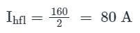
∴ Total power loss at half full load condition is given as,
Phfl = I2hfl × R02
Phfl = 802 × 0.0335
Phfl = 214.2 W
The full load voltage drop in a 1-phase transformer is 2% and 4% respectively due to resistance and leakage reactance. Then the voltage drop is maximum at __________- a)0.45 lagging
- b)0.45 leading
- c)0.9 lagging
- d)0.9 leading
Correct answer is option 'A'. Can you explain this answer?
The full load voltage drop in a 1-phase transformer is 2% and 4% respectively due to resistance and leakage reactance. Then the voltage drop is maximum at __________
a)
0.45 lagging
b)
0.45 leading
c)
0.9 lagging
d)
0.9 leading
| | Vibhor Goyal answered |
Z = 4.47; cosθ = percentage r/percentage z = 2/(4.47) = 0.45.
It is possible to attain maximum efficiency in a transformer when the ______- a)core losses are equal to rated full load copper losses
- b)core losses are more than rated full load copper losses
- c)core losses and full load copper losses are constant
- d)copper loss also becomes constant
Correct answer is option 'A'. Can you explain this answer?
It is possible to attain maximum efficiency in a transformer when the ______
a)
core losses are equal to rated full load copper losses
b)
core losses are more than rated full load copper losses
c)
core losses and full load copper losses are constant
d)
copper loss also becomes constant
 | Crack Gate answered |
Maximum efficiency is achieved at the condition when fixed core losses and copper losses at rated condition are equal.
If the per unit leakage impedance for the primary of a transformer is ‘x’ on the given rated base value. If the voltage and volt-amperes are doubled, then the changed per unit impedance will be- a)0.5x
- b)2x
- c)4x
- d)x
Correct answer is option 'A'. Can you explain this answer?
If the per unit leakage impedance for the primary of a transformer is ‘x’ on the given rated base value. If the voltage and volt-amperes are doubled, then the changed per unit impedance will be
a)
0.5x
b)
2x
c)
4x
d)
x
| | Swara Dasgupta answered |
pu(new base)=(x)*(MVA(new)/MVA(old))*(kV(old)/kV(new))^2
=x*2*(1/4)
=0.5x.
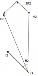
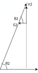
In a transformer, the load current is kept constant, while the power factor is varied. Under this situation, zero voltage regulation will be observed- a)independent of load power factor
- b)load power factor is leading
- c)load power factor is lagging
- d)at power factor equal to unity
Correct answer is option 'B'. Can you explain this answer?
In a transformer, the load current is kept constant, while the power factor is varied. Under this situation, zero voltage regulation will be observed
a)
independent of load power factor
b)
load power factor is leading
c)
load power factor is lagging
d)
at power factor equal to unity
| | Engineers Adda answered |
Voltage regulation is the change in secondary terminal voltage from no load to full load at a specific power factor of load and the change is expressed in percentage.
E2 = no-load secondary voltage
V2 = full load secondary voltage
Voltage regulation for the transformer is given by the ratio of change in secondary terminal voltage from no load to full load to no load secondary voltage.
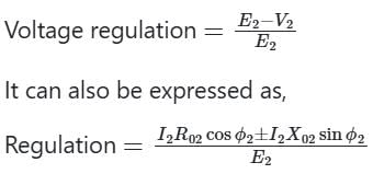
+ sign is used for lagging loads and
+ sign is used for lagging loads and
- ve sign is used for leading loads
Hence voltage regulation can be negative only for capacitive loads
In transformer minimum voltage regulation occurs when the power factor of the load is leading.
The voltage regulation of the transformer is zero at a leading power factor load such as a capacitive load.
For zero voltage regulation, E2 = V2
> IR cos φ = IX sin φ (negative sign represents leading power factor loads)
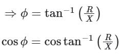
This is the leading power factor at which voltage regulation becomes zero while supplying the load.
This is the leading power factor at which voltage regulation becomes zero while supplying the load.
The value of flux involved m the e.m.f. equation of a transformer is- a)average value
- b)r.m.s. value
- c)maximum value
- d)instantaneous value
Correct answer is option 'C'. Can you explain this answer?
The value of flux involved m the e.m.f. equation of a transformer is
a)
average value
b)
r.m.s. value
c)
maximum value
d)
instantaneous value
| | Swati Shah answered |
The value of flux involved in the e.m.f. equation of a transformer is the maximum value. Here's why:
Explanation:
- The e.m.f. equation of a transformer is given by E = 4.44fφN, where E is the induced e.m.f., f is the frequency of the alternating current, φ is the maximum value of the flux, and N is the number of turns in the winding.
- The maximum value of the flux is the peak value of the sinusoidal waveform of the flux. This is because the e.m.f. induced in the winding of the transformer is proportional to the rate of change of flux, and the maximum rate of change occurs when the flux is changing from its maximum to its minimum value.
- The average value of the flux is zero, since the flux waveform is symmetrical about the zero axis.
- The r.m.s. value of the flux is given by the square root of the mean square value of the waveform, which is √(1/2φ²). This value is not relevant to the e.m.f. equation of a transformer.
- The instantaneous value of the flux is constantly changing, and is not a useful value to consider for the e.m.f. equation of a transformer.
Conclusion:
Therefore, the value of flux involved in the e.m.f. equation of a transformer is the maximum value.
Transformers with high leakage impedance is used in ___________- a)arc welding
- b)power distribution
- c)power generating terminals
- d)none of the mentioned
Correct answer is option 'A'. Can you explain this answer?
Transformers with high leakage impedance is used in ___________
a)
arc welding
b)
power distribution
c)
power generating terminals
d)
none of the mentioned
| | Vibhor Goyal answered |
The feature of the high impedance is extracted in the arc welding applications.
A single phase transformer of 2200/220 V having rated l.v. current of 150 A has to undergo open circuit test on h.v side. The instruments used are voltmeter of 200V and ammeter of 1A. Then the results ___________- a)will be wrong
- b)will be accurate
- c)of ammeter will burn
- d)none of the mentioned
Correct answer is option 'C'. Can you explain this answer?
A single phase transformer of 2200/220 V having rated l.v. current of 150 A has to undergo open circuit test on h.v side. The instruments used are voltmeter of 200V and ammeter of 1A. Then the results ___________
a)
will be wrong
b)
will be accurate
c)
of ammeter will burn
d)
none of the mentioned
 | Vertex Academy answered |
The current in the h.v. winding will be around 10 A but the ammeter is of 1 A rating. So, it will burn off.
Which of the following conditions have to ensured for a open-circuit test?A. Performed on L.V side
B. Leakage impedance can be obtained
C. It is performed at rated voltage
D. It gives magnetizing impedance- a)B, D
- b)A, B, C
- c)B, C, D
- d)A, C, D
Correct answer is option 'D'. Can you explain this answer?
Which of the following conditions have to ensured for a open-circuit test?
A. Performed on L.V side
B. Leakage impedance can be obtained
C. It is performed at rated voltage
D. It gives magnetizing impedance
B. Leakage impedance can be obtained
C. It is performed at rated voltage
D. It gives magnetizing impedance
a)
B, D
b)
A, B, C
c)
B, C, D
d)
A, C, D
 | Machine Experts answered |
Leakage impedance is not found from open-circuit test.
Which of the following conditions have to ensured for a short-circuit test?A. h.v. winding is short-circuited
B. It helps in calculation of voltage regulation
C. It is performed at rated voltage
D. l.v. winding is short-circuited- a)B, D
- b)A, B, C
- c)B, C, D
- d)A, C
Correct answer is option 'A'. Can you explain this answer?
Which of the following conditions have to ensured for a short-circuit test?
A. h.v. winding is short-circuited
B. It helps in calculation of voltage regulation
C. It is performed at rated voltage
D. l.v. winding is short-circuited
B. It helps in calculation of voltage regulation
C. It is performed at rated voltage
D. l.v. winding is short-circuited
a)
B, D
b)
A, B, C
c)
B, C, D
d)
A, C
| | Crack Gate answered |
For conducting short circuit test, l.v. winding is short circuited and it is not performed at rated voltage.

Which of the following conditions have to ensured for a open-circuit test?A. Performed on L.V side
B. Leakage impedance can be obtained
C. It is performed at 10-12% of rated voltage
D. It gives magnetizing impedance- a)B, D
- b)A, B, C
- c)B, C, D
- d)A, D
Correct answer is option 'A'. Can you explain this answer?
Which of the following conditions have to ensured for a open-circuit test?
A. Performed on L.V side
B. Leakage impedance can be obtained
C. It is performed at 10-12% of rated voltage
D. It gives magnetizing impedance
B. Leakage impedance can be obtained
C. It is performed at 10-12% of rated voltage
D. It gives magnetizing impedance
a)
B, D
b)
A, B, C
c)
B, C, D
d)
A, D
| | Vibhor Goyal answered |
Leakage impedance is not found from open-circuit test. And it is performed on the rated voltage to account for core losses.
Which of the following informations are obtained from short-circuit test?I. Ohmic losses at rated current
II. Equivalent resistance and leakage reactance
III. Core losses
IV. Voltage regulation- a)I, II, IV
- b)II, III
- c)I, II, III
- d)II, III, IV
Correct answer is option 'A'. Can you explain this answer?
Which of the following informations are obtained from short-circuit test?
I. Ohmic losses at rated current
II. Equivalent resistance and leakage reactance
III. Core losses
IV. Voltage regulation
II. Equivalent resistance and leakage reactance
III. Core losses
IV. Voltage regulation
a)
I, II, IV
b)
II, III
c)
I, II, III
d)
II, III, IV
| | Sanaya Basu answered |
Short-Circuit Test Information
- Ohmic losses at rated current: The short-circuit test provides information about the ohmic losses that occur in the transformer windings when they are subjected to rated current.
- Equivalent resistance and leakage reactance: By performing the short-circuit test, the equivalent resistance and leakage reactance of the transformer can be determined. This information is crucial for understanding the transformer's impedance characteristics.
- Core losses: The core losses of the transformer can also be estimated from the short-circuit test results. This helps in assessing the overall efficiency of the transformer.
- Voltage regulation: The short-circuit test data can be used to calculate the voltage regulation of the transformer. Voltage regulation is an important parameter that indicates how well the transformer can maintain a constant output voltage under varying load conditions.
In conclusion, the short-circuit test provides valuable information related to ohmic losses, equivalent resistance, leakage reactance, core losses, and voltage regulation of a transformer. This data is essential for analyzing the performance and efficiency of the transformer in practical applications.
Transformer operating in parallel will share a common load in the best possible manner if- a)leakage impedances are proportional to their kVA rating
- b)pu leakage impedances are equal
- c)leakage impedances are equal
- d)any of the mentioned
Correct answer is 'B'. Can you explain this answer?
Transformer operating in parallel will share a common load in the best possible manner if
a)
leakage impedances are proportional to their kVA rating
b)
pu leakage impedances are equal
c)
leakage impedances are equal
d)
any of the mentioned
 | Shivam Sharma answered |
For same pu leakage impedance, parallel operation of transformers become feasible.
If the supply frequency to the transformer is increased, the iron loss will- a)not change
- b)decrease
- c)increase
- d)any of the above
Correct answer is option 'C'. Can you explain this answer?
If the supply frequency to the transformer is increased, the iron loss will
a)
not change
b)
decrease
c)
increase
d)
any of the above
| | Sparsh Saini answered |
As frequency increases, the flux density in the core decreases but as the iron loss is directly proportional to the frequency hence effect of increased frequency will be reflected in increase of the iron losses.
A 4000 V/2000 V, 60 Hz single phase transformer has a total impedance of 60 Ω referred to the primary side. The primary and secondary windings have negligible resistances. If the transformer supplies a resistive of 20 Ω, the full load voltage at the secondary side will be- a)1143 V
- b)1600 V
- c)2000 V
- d)3200 V
Correct answer is option 'A'. Can you explain this answer?
A 4000 V/2000 V, 60 Hz single phase transformer has a total impedance of 60 Ω referred to the primary side. The primary and secondary windings have negligible resistances. If the transformer supplies a resistive of 20 Ω, the full load voltage at the secondary side will be
a)
1143 V
b)
1600 V
c)
2000 V
d)
3200 V
| | Machine Experts answered |
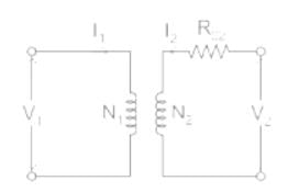
Concept:
Consider a two winding single phase transformer as shown below,
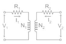
N1 = primary winding turns
N2 = secondary winding turns
V1 = primary winding voltage
V2 = secondary winding voltage
I1 = current through the primary winding
I2 = current through the secondary winding
Transformation ratio: It is defined as the ratio of the secondary voltage to the primary voltage. It is denoted by k.
K=N2N1=V2V1=I1I2" tabindex="0">K=N2N1=V2V1=I1I----- (1)Transformer equivalent circuit with respect to secondary can be represented a show below
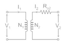
Where R02 = Effective resistance referred to the secondary side of the transformer.
R02 = R2 + R1' ........ (2)
R1' = Primary winding resistance as referred to the secondary side.
R1' = R1 × k2 ......... (3)
Similarly, the effective resistance referred to the primary side of the transformer is given as,
R01 = R1 + R2'
R2' = Secondary winding resistance as referred to the primary side.
R2' = R2 / k2
Calculation:
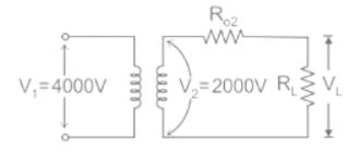
Given total impedance of the transformer referred to primary R01 = 60 Ω
Transformation ratio k = V2 / V1 = 2000 / 4000 = 0.5
Total impedance of the transformer referred to secondary when primary and secondary windings have negligible resistances is given as
R02 = R01 × k2
= 60 / 4 = 15 Ω
Apply the voltage division rule to find voltage across the load
VL = 2000 × 20 / (15 + 20)
VL = 1143 V
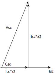
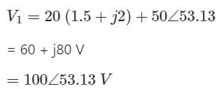
The single phase converter has a full load secondary current of 200 A, while the primary current is one-tenth of this value. Its primary resistance and secondary winding resistances are 1.5 Ω and 0.015 Ω, respectively. The leakage reactance values of the primary and secondary windings are 2 Ω and 0.02 Ω respectively. Which primary voltage will transmit the full load current through a short-circuit secondary, not neglecting the load current?- a)80 V
- b)120 V
- c)100 V
- d)40 V
Correct answer is option 'C'. Can you explain this answer?
The single phase converter has a full load secondary current of 200 A, while the primary current is one-tenth of this value. Its primary resistance and secondary winding resistances are 1.5 Ω and 0.015 Ω, respectively. The leakage reactance values of the primary and secondary windings are 2 Ω and 0.02 Ω respectively. Which primary voltage will transmit the full load current through a short-circuit secondary, not neglecting the load current?
a)
80 V
b)
120 V
c)
100 V
d)
40 V
| | Crack Gate answered |
Calculation:
Given:
Primary resistance of Transformer R1 = 1.5 Ω
The primary reactance of Transformer X1 = 2j Ω
Secondary resistance of Transformer R2 = 0.015 Ω
Secondary reactance of Transformer X2 = 0.02j Ω
Primary Current I1 = 20 A
Secondary Current I2 = 200 A
Let Primary Induced Emf and Secondary Induced Emf be E1 and E2
Let primary Voltage be V1
Circuit Diagram Shown:
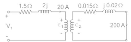
E2 = 200 (0.015 + j0.02)
E2 = 5∠ 53.13
Turns ratio (N) is given by
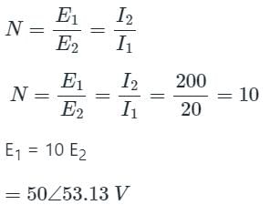
Now, by Applying KCL in Primary Circuit
The magnetisation branch of an equivalent circuit of a transformer is drawn in ________ with supply voltage.- a)both series and parallel
- b)series only
- c)parallel only
- d)Neither series nor parallel
Correct answer is option 'C'. Can you explain this answer?
The magnetisation branch of an equivalent circuit of a transformer is drawn in ________ with supply voltage.
a)
both series and parallel
b)
series only
c)
parallel only
d)
Neither series nor parallel
| | Machine Experts answered |
Concept:
The equivalent circuit of the transformer is
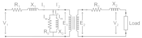
I1 = Primary winding current
I2 ' =Secondary winding current referred to the primary side
I0 = NO - load current
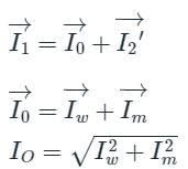
Iw = Core loss component
Im = magnetizing component No-load current is almost the same when we apply the load also.
The magnetizing branch circuit is connected in parallel to the supply voltage as the No-load current is constant while we apply load also. Therefore Core loss is also constant as I0 remains constant
Two single phase transformers A and B are operating in parallel having same impedance. But the x/r ratio of them are not equal and xa > xb. Then- a)A has poorer pf than B
- b)B has poorer pf than B
- c)lesser power factor angle
- d)both operate at same power factor
Correct answer is option 'A'. Can you explain this answer?
Two single phase transformers A and B are operating in parallel having same impedance. But the x/r ratio of them are not equal and xa > xb. Then
a)
A has poorer pf than B
b)
B has poorer pf than B
c)
lesser power factor angle
d)
both operate at same power factor
| | Swati Tiwari answered |
It is not clear what you mean by "xa" in the question. If you provide more information, I can try to help you further.
A single phase transformer of 2200/220 V having rated l.v. current of 150 A has to undergo open circuit test on h.v. side. Which of the below instruments range should be used?- a)6A, 200V
- b)150A, 22V
- c)60A, 220V
- d)6A, 20V
Correct answer is option 'A'. Can you explain this answer?
A single phase transformer of 2200/220 V having rated l.v. current of 150 A has to undergo open circuit test on h.v. side. Which of the below instruments range should be used?
a)
6A, 200V
b)
150A, 22V
c)
60A, 220V
d)
6A, 20V
| | Bayshore Academy answered |
Open circuit test is conducted on l.v. side, so the measuring instruments will be on the h.v. side.
So the current in the h.v. side will be around 3-6% of the rated.
So the current in the h.v. side will be around 3-6% of the rated.
Which of the statements made here are incorrect regarding the transformer?I. Maximum voltage regulation occurs at the leading p.f.
II. Maximum voltage regulation occurs when load p.f. angle and impedance angle of the leakage impedance are same.
III. V.R. at zero p.f. is always zero.
IV. V.R. of a transformer may be negative at leading p.f.- a)I, II, III
- b)IV
- c)I, III
- d)I, IV, III
Correct answer is option 'B'. Can you explain this answer?
Which of the statements made here are incorrect regarding the transformer?
I. Maximum voltage regulation occurs at the leading p.f.
II. Maximum voltage regulation occurs when load p.f. angle and impedance angle of the leakage impedance are same.
III. V.R. at zero p.f. is always zero.
IV. V.R. of a transformer may be negative at leading p.f.
II. Maximum voltage regulation occurs when load p.f. angle and impedance angle of the leakage impedance are same.
III. V.R. at zero p.f. is always zero.
IV. V.R. of a transformer may be negative at leading p.f.
a)
I, II, III
b)
IV
c)
I, III
d)
I, IV, III
| | Prasad Saini answered |
Incorrect Statements Regarding the Transformer
There are four statements given regarding the transformer, and we need to identify which of them are incorrect. Let's analyze each statement one by one.
I. Maximum voltage regulation occurs at the leading p.f.
This statement is incorrect. Voltage regulation refers to the change in output voltage of a transformer when the load varies. The maximum voltage regulation occurs at the lagging power factor, not at the leading power factor. This is because at lagging power factor, the load current lags behind the voltage, resulting in a higher drop across the impedance of the transformer.
II. Maximum voltage regulation occurs when load p.f. angle and impedance angle of the leakage impedance are the same.
This statement is incorrect. The voltage regulation of a transformer depends on the power factor angle difference between the load and the transformer impedance. The maximum voltage regulation occurs when the load power factor angle is equal to the angle between the impedance of the transformer and the voltage. In other words, the maximum voltage regulation occurs when the load power factor angle is equal to the angle of the impedance voltage drop in the transformer.
III. V.R. at zero p.f. is always zero.
This statement is incorrect. The voltage regulation at zero power factor is not always zero. Zero power factor means that the load is purely reactive, and in this case, the voltage regulation can be significant. The reactive power causes additional losses in the transformer, resulting in a voltage drop.
IV. V.R. of a transformer may be negative at the leading p.f.
This statement is correct. The voltage regulation of a transformer can be negative at the leading power factor. Negative voltage regulation means that the output voltage of the transformer increases as the load increases. This can occur when the load power factor angle is leading and the impedance angle of the transformer is lagging.
Conclusion
Based on the analysis above, the incorrect statements regarding the transformer are:
I. Maximum voltage regulation occurs at the leading p.f.
II. Maximum voltage regulation occurs when load p.f. angle and impedance angle of the leakage impedance are the same.
III. V.R. at zero p.f. is always zero.
Therefore, the correct answer is option 'B', i.e., IV.
Which of the following is the correct mathematical relationship that connects primary and secondary parameters of a transformer?- a)(V2 / V1) = (N1 / N2) = (I1 / I2) = k
- b)(V2 / V1) = (N2 / N1) = (I2 / I1) = k
- c)(V2 / V1) = (N2 / N1) = (I1 / I2) = k
- d)(V2 / V1) = (N1 / N2) = (I2 / I1) = k
Correct answer is option 'C'. Can you explain this answer?
Which of the following is the correct mathematical relationship that connects primary and secondary parameters of a transformer?
a)
(V2 / V1) = (N1 / N2) = (I1 / I2) = k
b)
(V2 / V1) = (N2 / N1) = (I2 / I1) = k
c)
(V2 / V1) = (N2 / N1) = (I1 / I2) = k
d)
(V2 / V1) = (N1 / N2) = (I2 / I1) = k
| | Sushant Mehta answered |
Mathematical Relationship between Primary and Secondary Parameters of a Transformer
Transformer parameters are interconnected through a set of equations that relate primary and secondary values. The correct mathematical relationship is expressed as:
(V2 / V1) = (N2 / N1) = (I1 / I2) = k
Explanation:
- V2 / V1: Ratio of secondary voltage to primary voltage remains constant and is equal to the turns ratio of the transformer.
- N2 / N1: Ratio of secondary turns to primary turns is constant, indicating the turns ratio.
- I1 / I2: Ratio of primary current to secondary current is also constant and is inversely proportional to the turns ratio.
- k: Represents the transformation ratio, which remains constant for a given transformer.
This relationship is crucial in understanding the behavior of transformers and is utilized in various calculations and applications in electrical engineering. It helps in determining the voltage, current, and turns ratio between primary and secondary sides of the transformer, enabling efficient power transfer and voltage transformations.
For matching a circuit of output impedance 200 ohms with a load of 8 ohms, the turns ratio of the two winding of transformer should be- a)25
- b)1/25
- c)1/5
- d)5
Correct answer is option 'D'. Can you explain this answer?
For matching a circuit of output impedance 200 ohms with a load of 8 ohms, the turns ratio of the two winding of transformer should be
a)
25
b)
1/25
c)
1/5
d)
5
| | Crack Gate answered |
Concept:
Transformers are used for impedance matching applications. This is explained with the help of the following figure:
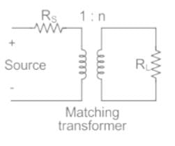
The load impedance reflected on the primary side is redrawn as shown:
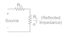
For the load to match with the source resistance:
Calculation:
With RL = 8 Ω, and RS = 200 Ω, the transformation ratio will be:
The efficiency of a 20 KVA, 2000/200 V, single phase transformer at unity pf is 98%. The given total losses at full load is 200 W. The pu resistance is?- a)0.01
- b)0.1
- c)1.0
- d)0.0196
Correct answer is option 'A'. Can you explain this answer?
The efficiency of a 20 KVA, 2000/200 V, single phase transformer at unity pf is 98%. The given total losses at full load is 200 W. The pu resistance is?
a)
0.01
b)
0.1
c)
1.0
d)
0.0196
| | Crack Gate answered |
pu resistance = Ohmic losses/KVA = 200/20000 = 0.01 pu.
The full load voltage drop in a 1-phase transformer is 2% and 4% respectively due to resistance and leakage reactance. Then the voltage drop is zero at __________- a)0.45 lagging
- b)0.45 leading
- c)0.9 lagging
- d)0.9 leading
Correct answer is option 'C'. Can you explain this answer?
The full load voltage drop in a 1-phase transformer is 2% and 4% respectively due to resistance and leakage reactance. Then the voltage drop is zero at __________
a)
0.45 lagging
b)
0.45 leading
c)
0.9 lagging
d)
0.9 leading
| | Machine Experts answered |
Z = 4.47; cosθ = percentage x/percentage z = 4/4.47 = 0.89.
Chapter doubts & questions for Single-Phase Transformers - Electrical Machines for Electrical Engg. 2026 is part of Electrical Engineering (EE) exam preparation. The chapters have been prepared according to the Electrical Engineering (EE) exam syllabus. The Chapter doubts & questions, notes, tests & MCQs are made for Electrical Engineering (EE) 2026 Exam. Find important definitions, questions, notes, meanings, examples, exercises, MCQs and online tests here.
Chapter doubts & questions of Single-Phase Transformers - Electrical Machines for Electrical Engg. in English & Hindi are available as part of Electrical Engineering (EE) exam. Download more important topics, notes, lectures and mock test series for Electrical Engineering (EE) Exam by signing up for free.
Electrical Machines for Electrical Engg.35 videos|96 docs|42 tests |