


All Exams > Electrical Engineering (EE) > Electrical Machines for Electrical Engg. > All Questions
All questions of Three-Phase Transformers for Electrical Engineering (EE) Exam
The primary and secondary of a transformer are ________ coupled but _______ connected.- a)magnetically, not electrically
- b)electrically, not magnetically
- c)magnetically, also magnetically
- d)electrically, also electrically
Correct answer is option 'A'. Can you explain this answer?
The primary and secondary of a transformer are ________ coupled but _______ connected.
a)
magnetically, not electrically
b)
electrically, not magnetically
c)
magnetically, also magnetically
d)
electrically, also electrically
| | Aniket Choudhury answered |
Transformer is the machine which has physical spacing and has magnetic circuit to exchange the voltage.
Hence Option (A) is correct
To access short notes on Single-phase Transformers click on the link given below

The delta-delta connections are used in applications of- a)large l.v. transformers
- b)small h.v. transformers
- c)large h.v. transformers
- d)small l.v. transformers
Correct answer is option 'A'. Can you explain this answer?
The delta-delta connections are used in applications of
a)
large l.v. transformers
b)
small h.v. transformers
c)
large h.v. transformers
d)
small l.v. transformers
| | Divya Singh answered |
Delta connected winding handle line voltages so it needs more turns in the winding but thin wires.
It was needed that to isolate dc noise coming from the transmitted signal, to attain the same which machine can be used without suffering significant loss- a)transformer
- b)dc machine
- c)induction machine
- d)stepper motor
Correct answer is option 'A'. Can you explain this answer?
It was needed that to isolate dc noise coming from the transmitted signal, to attain the same which machine can be used without suffering significant loss
a)
transformer
b)
dc machine
c)
induction machine
d)
stepper motor
| | Reham Sham answered |
We should use transformer to achive the isolation of dc
In an induction motor, if the rotor is locked, then the rotor frequency of induction motor will be:- a)Equal to the supply frequency
- b)Less than the supply frequency
- c)More than the supply frequency
- d)Zero
Correct answer is option 'A'. Can you explain this answer?
In an induction motor, if the rotor is locked, then the rotor frequency of induction motor will be:
a)
Equal to the supply frequency
b)
Less than the supply frequency
c)
More than the supply frequency
d)
Zero
| | Arshiya Basu answered |
Locked Rotor in an Induction Motor
Induction motors are commonly used in various industrial applications due to their simplicity and reliability. When the rotor of an induction motor is locked, it means that it cannot rotate freely. In this scenario, the rotor frequency of the induction motor will be:
Equal to the supply frequency
When the rotor is locked, the rotor frequency of the induction motor will match the supply frequency. This is because the rotor cannot rotate at a different speed than the rotating magnetic field created by the stator. Therefore, the rotor frequency will be synchronous with the supply frequency.
This synchronization between the rotor and supply frequency is essential for the motor to operate correctly. If the rotor frequency were different from the supply frequency, it would lead to inefficient operation and potential damage to the motor.
In conclusion, when the rotor of an induction motor is locked, the rotor frequency will be equal to the supply frequency to maintain synchronization between the rotor and the rotating magnetic field generated by the stator.
Which of the statements is/are correct regarding rotating magnetic field production in a 3-phase induction machine?
1. The direction of rotation of resultant flux in the air gap depends upon phase sequence.
2. The resultant flux of constant magnitude is produced in the air gap of the motor.
3. Frequency of rotating magnetic field is not the same as that of the supply frequency- a)1, 2 & 3
- b)1
- c)1 & 2
- d)2
Correct answer is option 'C'. Can you explain this answer?
Which of the statements is/are correct regarding rotating magnetic field production in a 3-phase induction machine?
1. The direction of rotation of resultant flux in the air gap depends upon phase sequence.
2. The resultant flux of constant magnitude is produced in the air gap of the motor.
3. Frequency of rotating magnetic field is not the same as that of the supply frequency
1. The direction of rotation of resultant flux in the air gap depends upon phase sequence.
2. The resultant flux of constant magnitude is produced in the air gap of the motor.
3. Frequency of rotating magnetic field is not the same as that of the supply frequency
a)
1, 2 & 3
b)
1
c)
1 & 2
d)
2
| | Luminary Institute answered |
Concept:
- If a balanced three-phase voltage is supplied to balanced three-phase windings in the stator of an Induction motor, the resultant flux remains constant in magnitude but rotates at the synchronous speed.
- Synchronous speed is related to the supply frequency and number of poles, for which the winding (stator) has been designed. This is termed as a rotating magnetic field formed in the air gap of the motor.

Where Ns = Synchronous speed in rpm
f = Supply frequency
P = Number of poles
- The direction of rotation of resultant flux in the air gap depends upon phase sequence. It rotates from the leading phase to the lagging phase.
- Frequency of rotating magnetic field is same as that of the supply frequency, while rotor frequency is slip times of supply frequency.
A transformer has comparitively much higher efficiency than a similar induction machine due to- a)small air gaps
- b)no moving parts
- c)strong coupling
- d)all of the mentioned
Correct answer is option 'D'. Can you explain this answer?
A transformer has comparitively much higher efficiency than a similar induction machine due to
a)
small air gaps
b)
no moving parts
c)
strong coupling
d)
all of the mentioned
| | Rajesh Saha answered |
Transformer does not has any moving components so losses are anyway reduced and also the coupling is very strong between two sides.
Consider two transformers X and Y having exact ratings, but have flux densities of 1.5T and 2T respectively. The weight of the transformer A per KVA will be- a)more than that of B
- b)lesser than that of B
- c)equal to that of B
- d)can not be said from the given data
Correct answer is option 'A'. Can you explain this answer?
Consider two transformers X and Y having exact ratings, but have flux densities of 1.5T and 2T respectively. The weight of the transformer A per KVA will be
a)
more than that of B
b)
lesser than that of B
c)
equal to that of B
d)
can not be said from the given data
| | Shivam Das answered |
Flux density = flux/Area.
Hence A has more area than B and so weight of A will be more than that of B.
Hence A has more area than B and so weight of A will be more than that of B.
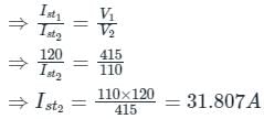
The starting line current of a 415V,3−phase, delta connected induction motor is 120A, when the rated voltage is applied to its stator winding. The starting line current at a reduced voltage of 110V, in ampere, is _________.
Correct answer is between '31,33'. Can you explain this answer?
The starting line current of a 415V,3−phase, delta connected induction motor is 120A, when the rated voltage is applied to its stator winding. The starting line current at a reduced voltage of 110V, in ampere, is _________.
 | Gate Funda answered |
At starting slip, S=1
Current Drawn α voltage
Current Drawn α voltage
Slip ring motor is preferred over Squirrel Cage motor when
1. High starting torque is required
2. Load torque is heavy
3. Heavy pull out torque is required- a)Only 3
- b)Only 1
- c)Only 1 and 2
- d)Only 2 and 3
Correct answer is option 'A'. Can you explain this answer?
Slip ring motor is preferred over Squirrel Cage motor when
1. High starting torque is required
2. Load torque is heavy
3. Heavy pull out torque is required
1. High starting torque is required
2. Load torque is heavy
3. Heavy pull out torque is required
a)
Only 3
b)
Only 1
c)
Only 1 and 2
d)
Only 2 and 3
| | Zoya Sharma answered |
- Starting torque is directly proportional to rotor resistance
- Squirrel cage induction motor has very low starting torque due to its rotor resistance of very low value
- We can’t add any external resistance as its rotor is short circuited through end rings
- But in case of slip ring motor, we can add external rotor resistance
- By increasing rotor resistance, we can shift the slip for max torque towards 1 slip, so, for a particular value of external resistance it is possible to achieve max torque during starting
- Slip ring motor is preferred over Squirrel Cage motor when high starting torque is required
- Squirrel cage motor has better running torque compared to slip ring motor
The leakage flux is the flux in side the transformer which- a)links either of the windings
- b)links both of the windings
- c)yoke of the core
- d)windows of the core
Correct answer is option 'A'. Can you explain this answer?
The leakage flux is the flux in side the transformer which
a)
links either of the windings
b)
links both of the windings
c)
yoke of the core
d)
windows of the core
| | Rajat Kumar answered |
Leakage flux is meant to to be loss as it does not link two windings.
A 2500 V, 50 Hz delta connected induction motor has a star connected slip ring rotor with a phase transformation ratio of 3.5. At standstill, the rotor resistance and leakage reactance are 0.04 and 0.6 Ω respectively. What is the value of rotor current at 4% slip with slip rings shorted?- a)714.286 A
- b)613.1 A
- c)2145.85 A
- d)None of these
Correct answer is option 'B'. Can you explain this answer?
A 2500 V, 50 Hz delta connected induction motor has a star connected slip ring rotor with a phase transformation ratio of 3.5. At standstill, the rotor resistance and leakage reactance are 0.04 and 0.6 Ω respectively. What is the value of rotor current at 4% slip with slip rings shorted?
a)
714.286 A
b)
613.1 A
c)
2145.85 A
d)
None of these
| | Saranya Mishra answered |
Respectively. The stator winding resistance and leakage reactance are 0.05 and 0.8 respectively. The rated stator current is 100 A.
To find the full-load slip of the motor, we can use the formula:
Slip = (Ns - Nr) / Ns
Where:
Ns = synchronous speed
Nr = rotor speed
The synchronous speed can be calculated using the formula:
Ns = (120 * f) / P
Where:
f = frequency
P = number of poles
Given:
f = 50 Hz
P = 3 (delta connected)
Ns = (120 * 50) / 3
Ns = 2000 rpm
Since the motor is at standstill, Nr = 0.
Slip = (2000 - 0) / 2000
Slip = 1
The full-load slip of the motor is 1.
To find the full-load rotor current, we can use the formula:
I2 = (s * Ir) / (s + 1)
Where:
I2 = rotor current
Ir = rated stator current
s = slip
Given:
Ir = 100 A
s = 1 (full-load slip)
I2 = (1 * 100) / (1 + 1)
I2 = 50 A
The full-load rotor current is 50 A.
To find the full-load rotor copper loss, we can use the formula:
Prcl = 3 * I2^2 * Rr
Where:
Prcl = rotor copper loss
I2 = rotor current
Rr = rotor resistance
Given:
I2 = 50 A
Rr = 0.04
Prcl = 3 * (50^2) * 0.04
Prcl = 300 * 0.04
Prcl = 12 kW
The full-load rotor copper loss is 12 kW.
To find the full-load rotor output, we can use the formula:
Pout = Prcl / (1 - s)
Where:
Pout = rotor output
Prcl = rotor copper loss
s = slip
Given:
Prcl = 12 kW
s = 1 (full-load slip)
Pout = 12 / (1 - 1)
Pout = 12 / 0
Pout = undefined
The full-load rotor output is undefined because the denominator becomes zero.
Please note that the calculations provided are based on the given information and assumptions.
The transformer which is more feasible to use in the distribution ends should be- a)star-delta
- b)delta-star
- c)scott
- d)delta-delta
Correct answer is option 'A'. Can you explain this answer?
The transformer which is more feasible to use in the distribution ends should be
a)
star-delta
b)
delta-star
c)
scott
d)
delta-delta
| | Bijoy Mehta answered |
Star-delta will have lower voltage at delta end.
In torque-slip characteristics of an induction motor, at normal speeds close to synchronism the torque is:- a)directly proportional to the slip
- b)not dependent on the slip
- c)maximum
- d)inversely proportional to the slip.
Correct answer is option 'A'. Can you explain this answer?
In torque-slip characteristics of an induction motor, at normal speeds close to synchronism the torque is:
a)
directly proportional to the slip
b)
not dependent on the slip
c)
maximum
d)
inversely proportional to the slip.
 | Naroj Boda answered |
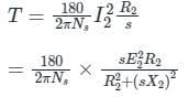
The torque in a three-phase induction motor is given by,
Observations:
1. At standstill,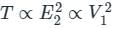
Torque is directly proportional to the square of the supply voltage.
2. For the low values of slip, i.e. for the speeds close to the synchronous speed
 i.e. the effective rotor circuit resistance is very large compared to the rotor reactance.
T ∝ s
Torque is directly proportional to slip. Thus, torque-slip characteristics are linear in the lower slip region.
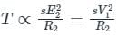
3. For the high values of slip, i.e. for the speeds away from the synchronous speed
 i.e. the effective rotor circuit resistance is very small compared to the rotor reactance.
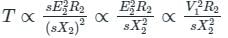
T ∝ 1/s
Torque is inversely proportional to slip. Thus, torque-slip characteristics are rectangular hyperbola at higher slip region.
Observations:
1. At standstill,
Torque is directly proportional to the square of the supply voltage.
2. For the low values of slip, i.e. for the speeds close to the synchronous speed
i.e. the effective rotor circuit resistance is very large compared to the rotor reactance.T ∝ s
Torque is directly proportional to slip. Thus, torque-slip characteristics are linear in the lower slip region.
3. For the high values of slip, i.e. for the speeds away from the synchronous speed
i.e. the effective rotor circuit resistance is very small compared to the rotor reactance.T ∝ 1/s
Torque is inversely proportional to slip. Thus, torque-slip characteristics are rectangular hyperbola at higher slip region.
A coupling magnetic field inside a rotating machine or static machine like transformers must involve withI. electrical system to extract energy from electrical system.II. mechanical system to extract energy from electrical system.- a)Only I is true
- b)Only II is true
- c)I and II are true
- d)I and II are false
Correct answer is option 'B'. Can you explain this answer?
A coupling magnetic field inside a rotating machine or static machine like transformers must involve with
I. electrical system to extract energy from electrical system.
II. mechanical system to extract energy from electrical system.
a)
Only I is true
b)
Only II is true
c)
I and II are true
d)
I and II are false
| | Puja Shah answered |
The energy conversion which involves both electrical as well as mechanical systems must have mutual field.
A 3 – phase, slip ring induction motor with delta connected rotor has an induced emf of 230 V between slip rings at standstill. Resistance and leakage reactance are 0.5 and 2.5 Ω respectively at standstill. What is the rotor current per phase at rotor developing maximum torque?- a)68.13 A
- b)65.06 A
- c)70.16 A
- d)74.07 A
Correct answer is option 'B'. Can you explain this answer?
A 3 – phase, slip ring induction motor with delta connected rotor has an induced emf of 230 V between slip rings at standstill. Resistance and leakage reactance are 0.5 and 2.5 Ω respectively at standstill. What is the rotor current per phase at rotor developing maximum torque?
a)
68.13 A
b)
65.06 A
c)
70.16 A
d)
74.07 A
| | Gate Funda answered |
We have, R2 = 0.5 Ω, X2 = 2.5 Ω
At maximum torque, R2 = sX2
Where s is the slip.
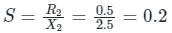
Impedance at maximum torque,
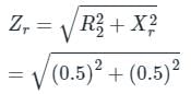
= 0.707 Ω (∵ Xr = sX2)
Standstill phase voltage in rotor is
E2=230V ( ∵ Delta connection)
Now rotor induced emf is
Er=sE2=0.2×230
= 46 V
Rotor current per phase,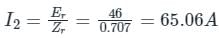
At maximum torque, R2 = sX2
Where s is the slip.
Impedance at maximum torque,
= 0.707 Ω (∵ Xr = sX2)
Standstill phase voltage in rotor is
E2=230V ( ∵ Delta connection)
Now rotor induced emf is
Er=sE2=0.2×230
= 46 V
Rotor current per phase,
In order to______ semi-closed slots or totally closed slots are used in induction motors.- a)improve starting torque
- b)improve power factor
- c)increase efficiency
- d)increase pull-one torque
Correct answer is option 'B'. Can you explain this answer?
In order to______ semi-closed slots or totally closed slots are used in induction motors.
a)
improve starting torque
b)
improve power factor
c)
increase efficiency
d)
increase pull-one torque
| | Anirban Gupta answered |
Improvement of Power Factor in Induction Motors using Semi-closed or Totally Closed Slots
Induction motors are widely used in various industrial applications due to their simplicity, reliability, and low cost. One of the important factors in the operation of induction motors is the power factor, which is a measure of how effectively electrical power is being converted into mechanical power.
Use of Semi-closed or Totally Closed Slots
- In order to improve the power factor of induction motors, semi-closed or totally closed slots are used in the motor design. These slots help in reducing the leakage flux and improving the magnetic flux distribution within the motor.
- By using semi-closed or totally closed slots, the flux leakage is minimized, which leads to a more efficient operation of the motor. This results in an improvement in the power factor of the motor.
Impact on Power Factor
- A higher power factor indicates a more efficient use of electrical power, as it indicates that a greater proportion of the power supplied to the motor is being converted into useful mechanical power.
- By using semi-closed or totally closed slots in the motor design, the power factor of the motor is improved, leading to a more efficient operation and reduced energy losses.
In conclusion, the use of semi-closed or totally closed slots in induction motors helps in improving the power factor of the motor, resulting in a more efficient and reliable operation.
A coupling magnetic field inside a rotating machine or static machine like transformers must involve with- a)both electrical and mechanical
- b)electrical parts
- c)mechanical parts
- d)either of the electrical or mechanical parts
Correct answer is option 'A'. Can you explain this answer?
A coupling magnetic field inside a rotating machine or static machine like transformers must involve with
a)
both electrical and mechanical
b)
electrical parts
c)
mechanical parts
d)
either of the electrical or mechanical parts
| | Prasad Verma answered |
The coupling field should interact with both the electrical as well as mechanical parts in order to achieve electromechanical energy conversion.
If the full load speed of a 3 phase 50 Hz 6 pole induction motor is 950 rpm. What is its half load speed nearly equal to- a)1000 rpm
- b)450 rpm
- c)1900 rpm
- d)975 rpm
Correct answer is option 'D'. Can you explain this answer?
If the full load speed of a 3 phase 50 Hz 6 pole induction motor is 950 rpm. What is its half load speed nearly equal to
a)
1000 rpm
b)
450 rpm
c)
1900 rpm
d)
975 rpm
| | Pooja Patel answered |
The synchronous speed of induction motor,
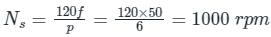
At full load, slip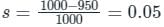
We know that slip is directly proportional to load, hence at half load slip will be 0.025
At half load rotor speed, Nr = Ns (1 - s) = 1000 (1 - 0.025) = 975 rpm
At full load, slip
We know that slip is directly proportional to load, hence at half load slip will be 0.025
At half load rotor speed, Nr = Ns (1 - s) = 1000 (1 - 0.025) = 975 rpm
Which of the following 3-phase connections of a transformer is rarely used?- a)Star-star
- b)Delta-delta
- c)Star-delta
- d)Delta-star
Correct answer is option 'A'. Can you explain this answer?
Which of the following 3-phase connections of a transformer is rarely used?
a)
Star-star
b)
Delta-delta
c)
Star-delta
d)
Delta-star
 | EduRev GATE answered |
Concept:
- Star-star type of transformer is rarely used due to problems with unbalanced loads.
- It is economical for small high voltage transformers as the number of turns per phase and the amount of insulation required is less.
Applications of different three-phase transformers:
- Delta – star connection type three-phase transformer is used for both large and low voltage rating transformers.
- Delta – star transformer is used at the generator side to step up the voltage levels
- Star – delta transformer is used at the load side of distribution systems to step down the voltage levels.
- Star – star connection transformers are used for small, high voltage transformers.
- Delta – delta connection transformers are used for large, low voltage transformers.
A V-V connected transformer can be connected in parallel to delta-delta connected transformer but not to- a)delta-star
- b)star-delta
- c)star-V
- d)all of the mentioned
Correct answer is option 'A'. Can you explain this answer?
A V-V connected transformer can be connected in parallel to delta-delta connected transformer but not to
a)
delta-star
b)
star-delta
c)
star-V
d)
all of the mentioned
| | Arpita Banerjee answered |
The V-V connected transformer and D-D connected transformers have same phase displacement, so they only can be connected in parallel to each other.
Three units of single phase transformers and one single three-phase transformer rating- a)will be same for one rating
- b)can never be made same
- c)may be same
- d)none of the mentioned
Correct answer is option 'A'. Can you explain this answer?
Three units of single phase transformers and one single three-phase transformer rating
a)
will be same for one rating
b)
can never be made same
c)
may be same
d)
none of the mentioned
 | Baishali Bajaj answered |
It is found that generation, transmission and distribution of electrical power are more economical in three phase system than single phase system. For three phase system three single phase transformers are required. Three phase transformation can be done in two ways, by using single three phase transformer or by using a bank of three single phase transformers. Both are having some advantages over other. Single 3 phase transformer costs around 15 % less than bank of three single phase transformers. Again former occupies less space than later. For very big transformer, it is impossible to transport large three phase transformer to the site and it is easier to transport three single phase transformers which is erected separately to form a three phase unit.
If para magnetic core is used in the place of the ferromagnetic core of the transformer, then magnetostriction will- a)be vanished
- b)reduce
- c)increase
- d)not be affected
Correct answer is option 'A'. Can you explain this answer?
If para magnetic core is used in the place of the ferromagnetic core of the transformer, then magnetostriction will
a)
be vanished
b)
reduce
c)
increase
d)
not be affected
| | Prasad Saini answered |
If the core is not ferromagnetic then the transformer will not operate at all so no humming sound.
A 4 pole induction machine is working as an induction generator. The generator supply frequency is 60 Hz. The rotor current frequency is 5 Hz. The mechanical speed of the rotor in RPM is- a)1350
- b)1650
- c)1950
- d)2250
Correct answer is option 'C'. Can you explain this answer?
A 4 pole induction machine is working as an induction generator. The generator supply frequency is 60 Hz. The rotor current frequency is 5 Hz. The mechanical speed of the rotor in RPM is
a)
1350
b)
1650
c)
1950
d)
2250
| | Naroj Boda answered |
When 3-ϕ induction machine working as an induction generator, then
Slip (s) =
Where,
Ns = Synchronous speed
Nr = Rotor speed
Frequency of rotor current = s × f
Where s is the slip
f is the supply frequency
Slip (s) =
Where,
Ns = Synchronous speed
Nr = Rotor speed
Frequency of rotor current = s × f
Where s is the slip
f is the supply frequency
Calculation:
Given that,
Supply frequency (fs) = 60 Hz
Rotor current frequency (fr) = 5 Hz
Number of poles = 4
Synchronous speed,
We know that,
fr = (s) fs
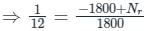
⇒ 5 = (s) (60)
⇒ s = 1/12
To work as an induction generator, rotor speed should be slip speed greater than synchronous speed, therefore
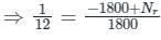
⇒ Nr = 1950 rpm
Given that,
Supply frequency (fs) = 60 Hz
Rotor current frequency (fr) = 5 Hz
Number of poles = 4
Synchronous speed,
We know that,
fr = (s) fs
⇒ 5 = (s) (60)
⇒ s = 1/12
To work as an induction generator, rotor speed should be slip speed greater than synchronous speed, therefore
⇒ Nr = 1950 rpm
The speed of rotating magnetic field of a 3ϕ, 50 Hz slip ring induction motor running at a speed of 960 rpm will be:- a)1500 rpm
- b)1000 rpm
- c)3000 rpm
- d)960 rpm
Correct answer is option 'B'. Can you explain this answer?
The speed of rotating magnetic field of a 3ϕ, 50 Hz slip ring induction motor running at a speed of 960 rpm will be:
a)
1500 rpm
b)
1000 rpm
c)
3000 rpm
d)
960 rpm
| | Partho Saha answered |
Speed of rotating magnetic field of a slip ring induction motor
The speed of the rotating magnetic field in a slip ring induction motor is determined by the frequency of the power supply and the number of poles in the motor. The rotation speed of the magnetic field is known as the synchronous speed.
Formula for synchronous speed:
Synchronous speed (Ns) = (120 * Frequency) / Number of Poles
In this case, the frequency of the power supply is given as 50 Hz and the motor has not been specified to have a certain number of poles.
Calculating the synchronous speed:
Synchronous speed (Ns) = (120 * 50) / Number of Poles
Since the number of poles in the motor is not specified, we cannot determine the exact synchronous speed.
However, we are given that the motor is running at a speed of 960 rpm (revolutions per minute).
Calculating the actual speed:
Actual speed = 960 rpm
The actual speed of the motor is less than the synchronous speed because of slip. Slip is the difference between the synchronous speed and the actual speed of the motor. It is expressed as a percentage of the synchronous speed.
Calculating slip:
Slip = (Synchronous speed - Actual speed) / Synchronous speed
Since the actual speed is less than the synchronous speed, the slip will be a positive value.
Now, if we assume the slip to be small, we can approximate the synchronous speed as follows:
Synchronous speed ≈ Actual speed
Therefore, the speed of the rotating magnetic field of the slip ring induction motor running at a speed of 960 rpm would be approximately 960 rpm.
Hence, the correct answer is option 'd) 960 rpm'.
A three-phase transformer, connected in star-delta, is composed of three single-phase transformers, each rated 127 V / 13.2 kV. The line-to-line voltage ratio for the three-phase transformer is:- a)220 / 13.2 kV
- b)127 / 13.2 kV
- c)127 / 220 kV
- d)220 / 220 kV
Correct answer is option 'A'. Can you explain this answer?
A three-phase transformer, connected in star-delta, is composed of three single-phase transformers, each rated 127 V / 13.2 kV. The line-to-line voltage ratio for the three-phase transformer is:
a)
220 / 13.2 kV
b)
127 / 13.2 kV
c)
127 / 220 kV
d)
220 / 220 kV
| | Anshika Khanna answered |
The Problem:
We have a three-phase transformer connected in star-delta configuration. Each single-phase transformer in the system is rated at 127 V on the low voltage side and 13.2 kV on the high voltage side. We need to determine the line-to-line voltage ratio for the three-phase transformer.
Understanding the Star-Delta Connection:
In a star-delta connection, the primary winding of the transformer is connected in a star (Y) configuration, while the secondary winding is connected in a delta (∆) configuration. This type of connection is commonly used in power transmission systems to step up the voltage from the generator (star side) to the transmission line (delta side).
Line-to-Line Voltage Ratio:
To determine the line-to-line voltage ratio, we need to consider the transformation ratio of each single-phase transformer in the system. In a star-delta configuration, the line-to-line voltage ratio is given by the ratio of the high voltage (delta side) to the low voltage (star side).
Calculation:
The given rating of each single-phase transformer is 127 V / 13.2 kV. This means that the low voltage side has a rating of 127 V, while the high voltage side has a rating of 13.2 kV.
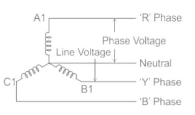
Since the low voltage side is connected in a star configuration, the line voltage is equal to the phase voltage. Therefore, the line voltage on the low voltage side is 127 V.
On the high voltage side, the line voltage is equal to the square root of 3 times the phase voltage. So, the line voltage on the high voltage side is calculated as follows:
Line Voltage (delta side) = √3 x Phase Voltage
Line Voltage (delta side) = √3 x 13.2 kV
Line Voltage (delta side) = 22.8 kV
Therefore, the line-to-line voltage ratio for the three-phase transformer is:
Line-to-Line Voltage Ratio = Line Voltage (delta side) / Line Voltage (star side)
Line-to-Line Voltage Ratio = 22.8 kV / 127 V
Line-to-Line Voltage Ratio = 220 / 13.2 kV
The Correct Answer:
The correct answer is option 'A': 220 / 13.2 kV. This represents the line-to-line voltage ratio for the three-phase transformer connected in star-delta configuration.
We have a three-phase transformer connected in star-delta configuration. Each single-phase transformer in the system is rated at 127 V on the low voltage side and 13.2 kV on the high voltage side. We need to determine the line-to-line voltage ratio for the three-phase transformer.
Understanding the Star-Delta Connection:
In a star-delta connection, the primary winding of the transformer is connected in a star (Y) configuration, while the secondary winding is connected in a delta (∆) configuration. This type of connection is commonly used in power transmission systems to step up the voltage from the generator (star side) to the transmission line (delta side).
Line-to-Line Voltage Ratio:
To determine the line-to-line voltage ratio, we need to consider the transformation ratio of each single-phase transformer in the system. In a star-delta configuration, the line-to-line voltage ratio is given by the ratio of the high voltage (delta side) to the low voltage (star side).
Calculation:
The given rating of each single-phase transformer is 127 V / 13.2 kV. This means that the low voltage side has a rating of 127 V, while the high voltage side has a rating of 13.2 kV.
Since the low voltage side is connected in a star configuration, the line voltage is equal to the phase voltage. Therefore, the line voltage on the low voltage side is 127 V.
On the high voltage side, the line voltage is equal to the square root of 3 times the phase voltage. So, the line voltage on the high voltage side is calculated as follows:
Line Voltage (delta side) = √3 x Phase Voltage
Line Voltage (delta side) = √3 x 13.2 kV
Line Voltage (delta side) = 22.8 kV
Therefore, the line-to-line voltage ratio for the three-phase transformer is:
Line-to-Line Voltage Ratio = Line Voltage (delta side) / Line Voltage (star side)
Line-to-Line Voltage Ratio = 22.8 kV / 127 V
Line-to-Line Voltage Ratio = 220 / 13.2 kV
The Correct Answer:
The correct answer is option 'A': 220 / 13.2 kV. This represents the line-to-line voltage ratio for the three-phase transformer connected in star-delta configuration.
A wound rotor induction motor runs with a slip of 0.05 when developing full load torque. Its rotor resistance is 0.45 Ω per phase. If an external resistance of 0.50 Ω per phase is connected across the slip rings, what is the slip for full torque?- a)0.03
- b)0.06
- c)0.09
- d)0.1
Correct answer is option 'D'. Can you explain this answer?
A wound rotor induction motor runs with a slip of 0.05 when developing full load torque. Its rotor resistance is 0.45 Ω per phase. If an external resistance of 0.50 Ω per phase is connected across the slip rings, what is the slip for full torque?
a)
0.03
b)
0.06
c)
0.09
d)
0.1
| | Pooja Patel answered |
Concept:
Rotor resistance method of speed control:
Under load condition torque approximately
T ∝ (sV12) / (R2 + Re)
Rotor resistance method of speed control:
Under load condition torque approximately
T ∝ (sV12) / (R2 + Re)
- In this method, some external resistance is inserted under the load conditions.
- Then the slip of the induction motor increases to maintain the load torque constant.
- As slip is increased, the speed of the motor will be reduced to below the rated speed.
- In this method, the motor acts as a constant torque variable power drive.
For torque constant(T = k)
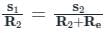
For induction motor, the torque in rotor resistance control methods is given as

For full load torque s α R2
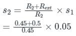
= 0.1055
For induction motor, the torque in rotor resistance control methods is given as
For full load torque s α R2
= 0.1055
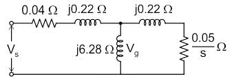
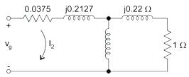
The figure shows the per-phase equivalent circuit of a two-pole three-phase induction motor operating at 50 Hz. The “air-gap” voltage, Vg across the magnetizing inductance, is 210 V rms, and the slip, is 0.05. The torque (in Nm) produced by the motor is _______.
Correct answer is between '400,403'. Can you explain this answer?
The figure shows the per-phase equivalent circuit of a two-pole three-phase induction motor operating at 50 Hz. The “air-gap” voltage, Vg across the magnetizing inductance, is 210 V rms, and the slip, is 0.05. The torque (in Nm) produced by the motor is _______.
 | Gate Gurus answered |
Exact Equivalent Circuit
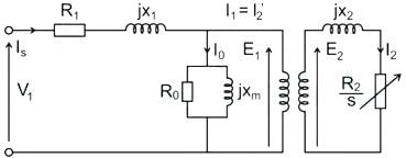
Here, R1 is the winding resistance of the stator
X1 is the inductance of the stator winding
R0 is the core loss component
XM is the magnetizing reaction of the winding
R2/s is the power of the rotor, which includes output mechanical power and loss of rotor
Important:
If we draw the circuit with refereed to the stator then the circuit will look like
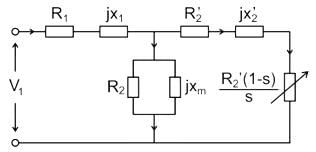
Here all the other parameters are same except R2’ is the rotor winding resistance with referred to stator winding. R2(1-s) / s is the resistance which shows the power which is mechanical power output or useful power. The power dissipated in that resistor is the useful power output or shaft power.
Explanation:
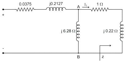
We redraw the given circuit as
Here, R1 is the winding resistance of the stator
X1 is the inductance of the stator winding
R0 is the core loss component
XM is the magnetizing reaction of the winding
R2/s is the power of the rotor, which includes output mechanical power and loss of rotor
Important:
If we draw the circuit with refereed to the stator then the circuit will look like
Here all the other parameters are same except R2’ is the rotor winding resistance with referred to stator winding. R2(1-s) / s is the resistance which shows the power which is mechanical power output or useful power. The power dissipated in that resistor is the useful power output or shaft power.
Explanation:
We redraw the given circuit as
Given Vg=210V,s=0.05
Air gap voltage is the voltage across AB, i.e.
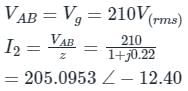
Hence, torque =

Air gap voltage is the voltage across AB, i.e.
Hence, torque =
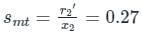
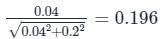
The rotor of a 3-phase induction motor has 0.04 Ω resistance per phase and 0.2 Ω standstill reactance per phase. An external resistance is used in the rotor circuit in order to get half of the maximum torque at starting. Neglect stator impedance. By what percentage will this external resistance change the power factor at starting?
Correct answer is between '30,35'. Can you explain this answer?
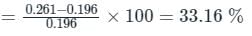
The rotor of a 3-phase induction motor has 0.04 Ω resistance per phase and 0.2 Ω standstill reactance per phase. An external resistance is used in the rotor circuit in order to get half of the maximum torque at starting. Neglect stator impedance. By what percentage will this external resistance change the power factor at starting?
| | Pooja Patel answered |
⇒ s2mt - 4smt + 1 = 0
⇒ smt = 3.73 (or) 0.27
smt = 3.72 is not valid.
So, smt = 0.27
⇒ r'2 = 0.2 x 0.27 = 0.054Ω
External resistance that must be inserted in the rotor circuit
= r'2 - r2 = 0.054 - 0.04 = 0.014Ω
Without external resistance,
Power factor =
With external resistance,
Power factor
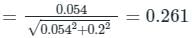
Percentage improvement in power factor
Which of the following is NOT an effect of single phasing in a three-phase induction motor?- a)Motor current is increasing 2.5 times to average current
- b)Motor will continue run from running position
- c)Motor cannot be increasing the heating
- d)Motor cannot be started from stop position
Correct answer is option 'C'. Can you explain this answer?
Which of the following is NOT an effect of single phasing in a three-phase induction motor?
a)
Motor current is increasing 2.5 times to average current
b)
Motor will continue run from running position
c)
Motor cannot be increasing the heating
d)
Motor cannot be started from stop position
| | Naroj Boda answered |
Concept:
Single phasing:
Single phasing:
- A three-phase motor must be connected to the rated load voltage and load for proper working. If due to some reason, one phase of the motor gets disconnected, the motor will continue to run from the active 2-phase supply. This is called single phasing.
- The motor will continue to run with vibration and reduced speed. However, depending upon the loading condition, the motor may/may not start on two phases.
- It will work satisfactorily if the motor carrying the load not more than 0.5 times rated load
- Single phasing is not desirable for the proper operation of the induction motors and appropriate measures should be taken to protect the machine.
Causes of single phasing:
- One of the three back up fuses blow (or fuse melts)
- One of the conductors of the motor is open-circuited.
- Wrong setting of the protection device provided on the motor.
- Relay contacts may be damaged or broken.
Effect of single phasing:
- Motor runs with reduced speed.
- It operates with uneven torque and produces a humming noise.
- Due to loss of current from one phase the current flowing through the remaining two phases increases. The winding insulation, at times, may not be designed to withstand the increased current and heat thereby damaging the insulation and causing short-circuited between the winding and the motor burns out.
- It may cause an overloading of the Generator.
- If the motor is arranged for stand by and automatic starting than the motor will not start and if the over relay provided fails to function the motor may burn.
When we magnetize the ferromagnetic core of the transformer, core length_______ and it ______ when demagnetized.- a)decreases, increases
- b)decreases, decreases
- c)increases,increases
- d)none of the mentioned
Correct answer is option 'A'. Can you explain this answer?
When we magnetize the ferromagnetic core of the transformer, core length_______ and it ______ when demagnetized.
a)
decreases, increases
b)
decreases, decreases
c)
increases,increases
d)
none of the mentioned
| | Sahana Sarkar answered |
Due to aligned magnetic dipoles in the material, the size will reduce by a small margin and vice versa while demagnetization.
The most widely used material in the core of the transformer is- a)cold rolled grain oriented sheet steel
- b)cold rolled grain steel
- c)soft iron
- d)steel
Correct answer is option 'A'. Can you explain this answer?
The most widely used material in the core of the transformer is
a)
cold rolled grain oriented sheet steel
b)
cold rolled grain steel
c)
soft iron
d)
steel
 | Swara Dasgupta answered |
CRGO has magnetization in the rolling direction and low core losses and very high permeability than present materials.
Induction generators deliver power at ______ power factor- a)Lagging
- b)Leading
- c)Unity
- d)Zero
Correct answer is option 'B'. Can you explain this answer?
Induction generators deliver power at ______ power factor
a)
Lagging
b)
Leading
c)
Unity
d)
Zero
| | Raj Singh answered |
Induction generators deliver power at Leading power factor
Induction generators are a type of electrical generator that are commonly used in wind turbines, hydroelectric power plants, and other renewable energy systems. Unlike synchronous generators, which require an external power source to produce a magnetic field, induction generators are self-excited and do not require a separate power source for their excitation.
Power factor
Power factor is a measure of how effectively electrical power is being used in a circuit. It is the ratio of real power (kW) to apparent power (kVA) and is expressed as a decimal or a percentage. Power factor can be either lagging (inductive) or leading (capacitive) depending on the nature of the load.
Leading power factor
A leading power factor occurs when the reactive power component of a load is capacitive. In other words, the load is capable of supplying reactive power to the system instead of consuming it. This can happen when there are capacitors or other reactive elements connected to the load.
Induction generators and leading power factor
Induction generators inherently operate at a leading power factor. This is because of the nature of the rotor windings in an induction generator. The rotor windings of an induction generator have a capacitive nature, which results in the generator producing a leading reactive power component.
When an induction generator is connected to a power system, it acts as a load and consumes real power from the system. However, it also produces a leading reactive power component, which effectively reduces the overall reactive power demand of the system. As a result, the power factor of the system is shifted towards leading.
Advantages of leading power factor
Operating an induction generator at a leading power factor has several advantages:
1. Improved voltage regulation: A leading power factor helps to improve the voltage regulation of the power system by reducing the reactive power demand.
2. Reduced line losses: Leading power factor reduces the line losses in the transmission and distribution system, resulting in improved efficiency.
3. Increased power transfer capability: Leading power factor allows for increased power transfer capability in the system, as it reduces the reactive power demand and frees up more capacity for real power transmission.
In conclusion, induction generators deliver power at a leading power factor due to the capacitive nature of their rotor windings. Operating at a leading power factor offers several advantages, including improved voltage regulation, reduced line losses, and increased power transfer capability.
A 4 pole induction machine is working as an induction generator. The generator supply frequency is 60 Hz. The rotor current frequency is 5 Hz. The mechanical speed of the rotor in RPM is- a)1350
- b)1650
- c)1950
- d)2250
Correct answer is option 'C'. Can you explain this answer?
A 4 pole induction machine is working as an induction generator. The generator supply frequency is 60 Hz. The rotor current frequency is 5 Hz. The mechanical speed of the rotor in RPM is
a)
1350
b)
1650
c)
1950
d)
2250
| | Zoya Sharma answered |
When 3-ϕ induction machine working as an induction generator, then
Slip (s) =
Where,
Ns = Synchronous speed
Nr = Rotor speed
Frequency of rotor current = s × f
Where s is the slip
f is the supply frequency
Calculation:
Given that,
Supply frequency (fs) = 60 Hz
Rotor current frequency (fr) = 5 Hz
Number of poles = 4
Synchronous speed,
We know that,
fr = (s) fs
⇒ 5 = (s) (60)

To work as an induction generator, rotor speed should be slip speed greater than synchronous speed, therefore
⇒ Nr = 1950 rpm
Slip (s) =
Where,
Ns = Synchronous speed
Nr = Rotor speed
Frequency of rotor current = s × f
Where s is the slip
f is the supply frequency
Calculation:
Given that,
Supply frequency (fs) = 60 Hz
Rotor current frequency (fr) = 5 Hz
Number of poles = 4
Synchronous speed,
We know that,
fr = (s) fs
⇒ 5 = (s) (60)
To work as an induction generator, rotor speed should be slip speed greater than synchronous speed, therefore
⇒ Nr = 1950 rpm
With reference to the delta-delta connection of a 3-phase transformer, state TRUE/FALSE for the following statements.1. It is satisfactory for both balanced and unbalanced loading.2. Third harmonic does not appear in the output voltage wave.- a)1 - TRUE, 2 - FALSE
- b)1 - FALSE, 2 - FALSE
- c)1 - TRUE, 2 - TRUE
- d)1 - FALSE, 2 - TRUE
Correct answer is option 'C'. Can you explain this answer?
With reference to the delta-delta connection of a 3-phase transformer, state TRUE/FALSE for the following statements.
1. It is satisfactory for both balanced and unbalanced loading.
2. Third harmonic does not appear in the output voltage wave.
a)
1 - TRUE, 2 - FALSE
b)
1 - FALSE, 2 - FALSE
c)
1 - TRUE, 2 - TRUE
d)
1 - FALSE, 2 - TRUE
| | EduRev GATE answered |
Delta connection in 3ϕ transformer:
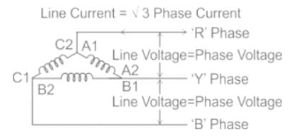
- In the delta connection, the line voltage is equal to the phase voltage.
- The line current is equal to √3 times of phase current.
- The delta-connected 3ϕ transformer can be used for both balanced and unbalanced loading.
- In the delta connection, the third harmonic component flows rounds the closed-loop of the delta.
- Hence, the third harmonic components are co-phased and hence cancel out in the line.
- So, the third harmonic does not appear in the output voltage wave.
With the addition of tertiary winding, the Y-Y connection becomes ______connection.- a)∆-Y-∆
- b)Y-∆-Y
- c)∆-Y-Y
- d)Y-Y-∆
Correct answer is option 'B'. Can you explain this answer?
With the addition of tertiary winding, the Y-Y connection becomes ______connection.
a)
∆-Y-∆
b)
Y-∆-Y
c)
∆-Y-Y
d)
Y-Y-∆
| | Malavika Nair answered |
Understanding Y-Y Connection with Tertiary Winding
When discussing power transformers, particularly in three-phase systems, the Y-Y (Wye-Wye) connection is a common configuration. The introduction of a tertiary winding modifies this connection.
What is a Tertiary Winding?
- A tertiary winding is an additional winding in a transformer, typically used for various purposes such as voltage stabilization, load balancing, or providing a path for circulating currents.
Impact of Tertiary Winding on Y-Y Connection
- When a tertiary winding is added to a Y-Y connection, it transforms the configuration into a Y-Y connection with enhanced functionalities.
- The resulting connection is denoted as Y--Y, where the double dash indicates the presence of the tertiary winding.
Advantages of Y--Y Connection
- Improved Voltage Regulation: The tertiary winding can help manage voltage drops, thus stabilizing output voltage.
- Harmonic Mitigation: It aids in reducing harmonic distortion in the system, providing cleaner power.
- Load Balancing: The tertiary winding can accommodate unbalanced loads more effectively, ensuring even distribution of current.
Conclusion
In summary, the addition of a tertiary winding to a Y-Y connection indeed changes its designation to Y--Y. This configuration offers multiple operational benefits, enhancing the performance of the transformer system in three-phase electrical applications. Understanding these connections is crucial for electrical engineers in optimizing transformer design and functionality.
The secondary winding of Distribution transformer is always connected in- a)Delta connection
- b)Star connection
- c)Line to Line connection
- d)Line to ground connection
Correct answer is option 'B'. Can you explain this answer?
The secondary winding of Distribution transformer is always connected in
a)
Delta connection
b)
Star connection
c)
Line to Line connection
d)
Line to ground connection
 | Bayshore Academy answered |
The secondary winding of the Distribution transformer is always connected in a star connection. This is done because:
- A distribution transformer is used to step down (reduce) the high voltage to the low voltage for supplying the consumer’s load. The high-to-low voltage conversion is possible only by star connection.
- The distribution of power to the domestic household is done in phase voltage. Hence, a phase with neutral is required which is possible only in a star connection.
- The delta connection does not provide neutral.
Star Connection:
In a star connection:

where, Vp = Phase Voltage
VL = Line Voltage
Delta Connection:
In delta connection:
VL = Vp
Neutral is absent in delta connection
We can employ transformers for a power range of- a)lower and higer values
- b)lower values
- c)higher values
- d)medium values
Correct answer is option 'A'. Can you explain this answer?
We can employ transformers for a power range of
a)
lower and higer values
b)
lower values
c)
higher values
d)
medium values
| | Mihir Khanna answered |
A transformer can be put in use upto a varying range of the power and it is usually available in readily in market.
A recording of the output of the emf induced for star and delta are recorded.Then shape of the emf induced in Y-connected 3-phase transformer is non sinusoidal in nature due to- a)3rd harmonic component of currents is absent
- b)3rd harmonic component of currents is present
- c)negative sequence component of current is present
- d)none of the mentioned
Correct answer is option 'A'. Can you explain this answer?
A recording of the output of the emf induced for star and delta are recorded.Then shape of the emf induced in Y-connected 3-phase transformer is non sinusoidal in nature due to
a)
3rd harmonic component of currents is absent
b)
3rd harmonic component of currents is present
c)
negative sequence component of current is present
d)
none of the mentioned
| | Rajat Kumar answered |
In a star connected transformer, closed path to generate 3rd harmonic is not there. So the emf shape will be peaky in nature.
Open delta transformers can be obtained from- a)delta-delta
- b)star-delta
- c)delta-star
- d)any of the mentioned
Correct answer is option 'A'. Can you explain this answer?
Open delta transformers can be obtained from
a)
delta-delta
b)
star-delta
c)
delta-star
d)
any of the mentioned
| | Jaya Dasgupta answered |
If one of the transformers is removed from the bank of only delta-delta, then it behaves with 58% power delivery.
A 400 V, 10 KVA transformer at 50 Hz, is operated at the frequency of 40 Hz, then the humming- a)increases
- b)decreases
- c)remains same
- d)increases to very high
Correct answer is option 'A'. Can you explain this answer?
A 400 V, 10 KVA transformer at 50 Hz, is operated at the frequency of 40 Hz, then the humming
a)
increases
b)
decreases
c)
remains same
d)
increases to very high
| | Anirban Gupta answered |
If the frequency is reduced, the core flux density increases, so the noise also will increase.
Name the starter which is very common and is used for cage motor design to run normally on delta connected stator winding.- a)Stator resistance starter
- b)Auto-transformer starter
- c)Star-delta starter
- d)Rotor resistance starter
Correct answer is option 'C'. Can you explain this answer?
Name the starter which is very common and is used for cage motor design to run normally on delta connected stator winding.
a)
Stator resistance starter
b)
Auto-transformer starter
c)
Star-delta starter
d)
Rotor resistance starter
| | Pooja Patel answered |
Methods used to start a three-phase cage-type induction motor:
DOL starter:
- The direct on line (DOL) starter method of an induction motor is simple and economical.
- In this method, the starter is connected directly to supply voltage.
- It also referred as Full Voltage Starting.
- In this method, small motors up to 5 hp rating are started to avoid the supply voltage fluctuation.
Star-delta starter:
- The star-delta starter method of starting three-phase induction motors is very common and widely used among all the methods.
- In this method, at stating motor in star connection and runs at delta connected stator windings.
Auto-transformer starter:
- The Autotransformer is used in both the type of the connections, i.e., either star connected or delta connected.
- The autotransformer is used to limit the starting current of the induction motor.
- This method is used for the high rating of squirrel cage induction motors. So, this method is most suitable for a 20 hp squirrel cage induction motor.
- The auto-transformer starter is expensive compare to the “direct on line” (DOL) starter
Which among the following is a type of three phase transformer connection?1. Star-Star connection2. Open Delta connection3. Scott connection- a)Only 1
- b)All 1, 2 & 3
- c)Only 2 & 3
- d)Only 1 & 2
Correct answer is option 'B'. Can you explain this answer?
Which among the following is a type of three phase transformer connection?
1. Star-Star connection
2. Open Delta connection
3. Scott connection
a)
Only 1
b)
All 1, 2 & 3
c)
Only 2 & 3
d)
Only 1 & 2
| | Surbhi Chopra answered |
Types of Three Phase Transformer Connections:
Star-Star Connection:
- In a star-star connection, the primary and secondary windings of the transformer are connected in a star configuration.
- This type of connection is commonly used in applications where the voltage ratio between the primary and secondary sides is 1:1.
- It provides a neutral point on both the primary and secondary sides, making it suitable for systems requiring a neutral connection.
Open Delta Connection:
- An open delta connection is a method of connecting three single-phase transformers to create a three-phase transformer.
- It is used when one of the transformers in a delta-delta connection fails, allowing the system to continue operating with reduced capacity.
- This connection is less efficient and can only handle a fraction of the three-phase power compared to a full three-phase transformer.
Scott Connection:
- A Scott connection is a type of transformer connection used to convert a three-phase system into a two-phase system.
- It consists of two transformers connected in a specific configuration to produce two output voltages that are 90 degrees out of phase with each other.
- This connection is primarily used in systems requiring a two-phase power supply, such as certain types of motors and rectifiers.
Conclusion:
All three types of transformer connections mentioned (Star-Star, Open Delta, and Scott) are valid types of three-phase transformer connections. Each connection has its own unique characteristics and applications, making them suitable for different scenarios in electrical systems.
It is advised that staggering of the butt joints- a)reduces reluctance of the path
- b)increases air gap
- c)increases mechanical strength
- d)all of the mentioned
Correct answer is option 'C'. Can you explain this answer?
It is advised that staggering of the butt joints
a)
reduces reluctance of the path
b)
increases air gap
c)
increases mechanical strength
d)
all of the mentioned
| | Pankaj Mehta answered |
Staggering is done for the steel butt joints of the transformer to gain more mechanical strength as the continuous air gap reduces the same.
In order to______ semi-closed slots or totally closed slots are used in induction motors.- a)improve starting torque
- b)improve power factor
- c)increase efficiency
- d)increase pull-one torque
Correct answer is option 'B'. Can you explain this answer?
In order to______ semi-closed slots or totally closed slots are used in induction motors.
a)
improve starting torque
b)
improve power factor
c)
increase efficiency
d)
increase pull-one torque
| | Pooja Patel answered |
Slots in Induction motor:
- The speed of the induction motor is inversely proportional to the load torque. In semi-closed and closed slots, the air gap between the stator and rotor is small as compared to open slots. As the air gap is small, the requirement of magnetizing current to establish the flux in the air gap is less.
- It results in improved power factor In order to semi-closed slots or totally closed slots are used in induction motors.
- Among all the three types of slots, semi-closed type slots are preferred for induction machines as semi-closed slots having the partial advantages of open type and partial advantages of closed type slots.
- Open-type slots are generally preferred for synchronous and dc machines.
- In general, closed type slots are used in low hp motors, to control the starting current, as the leakage reactance offered by closed type slots is very high compared to other types of slots.
- Large size induction motors use open slots so that already prepared and properly insulated coils can be easily inserted in open slots.
- In order to improve the power factor semi-closed slots or totally closed slots are used in induction motors.
The starter recommended for a 20 hp squirrel cage induction motor is:- a)Star delta starter
- b)Face plate starter
- c)Direct one line starter
- d)Auto transformer starter
Correct answer is option 'D'. Can you explain this answer?
The starter recommended for a 20 hp squirrel cage induction motor is:
a)
Star delta starter
b)
Face plate starter
c)
Direct one line starter
d)
Auto transformer starter
| | Jatin Mukherjee answered |
Starter for 20 HP Squirrel Cage Induction Motor
The recommended starter for a 20 HP squirrel cage induction motor is the auto transformer starter. The following points explain why:
What is an Auto Transformer Starter?
An auto transformer starter is a type of starter that uses a single winding auto transformer to reduce the voltage applied to the motor during starting. This type of starter is commonly used for squirrel cage induction motors.
Advantages of Auto Transformer Starter
The advantages of using an auto transformer starter for a 20 HP squirrel cage induction motor are:
1. Reduced Starting Current
The auto transformer starter reduces the starting current of the motor, which is important for preventing damage to the motor and reducing the stress on the electrical system.
2. Smooth Starting
The auto transformer starter provides a smooth starting current to the motor, which is important for preventing the motor from jerking or stalling during starting.
3. Cost Effective
The auto transformer starter is a cost-effective solution for starting a 20 HP squirrel cage induction motor, as it does not require expensive components or complex wiring.
4. Easy to Install
The auto transformer starter is easy to install and maintain, which makes it a popular choice for small to medium-sized motors.
Conclusion
In conclusion, the auto transformer starter is the recommended starter for a 20 HP squirrel cage induction motor due to its reduced starting current, smooth starting, cost-effectiveness, and ease of installation.
Delta / star transformer works satisfactorily when- a)load is balanced only
- b)load is unbalanced only
- c)on balanced as well as unbalanced loads
- d)none of the above
Correct answer is option 'C'. Can you explain this answer?
Delta / star transformer works satisfactorily when
a)
load is balanced only
b)
load is unbalanced only
c)
on balanced as well as unbalanced loads
d)
none of the above
| | EduRev GATE answered |
- Large unbalanced and balanced loads can be handled satisfactorily by a delta to star transformer.
- The star-delta & delta-star connection has no problem with third harmonic components due to circulating currents in the delta.
- It is also more stable to unbalanced loads since the delta connection partially redistributes any occurred imbalance.
Below is the circuit diagram for delta-delta transformer have a transformation ratio ‘k’. The current flowing in the windings of phase r-y in the below diagrams is
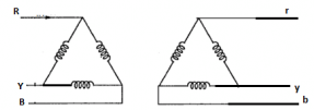
- a)k*I/1.73
- b)I/k*1.73
- c)1.73*k*I
- d)3*k*I
Correct answer is option 'A'. Can you explain this answer?
Below is the circuit diagram for delta-delta transformer have a transformation ratio ‘k’. The current flowing in the windings of phase r-y in the below diagrams is
a)
k*I/1.73
b)
I/k*1.73
c)
1.73*k*I
d)
3*k*I
| | Pallabi Pillai answered |
The phase current will be reduced by 1/1.73.
Which of the following is the correct use of 'delta/delta' connections?- a)This connection is economical for HV transformers.
- b)This is used for smaller power systems.
- c)This is the best match for ultra HV transformers.
- d)This suits large LV transformers.
Correct answer is option 'D'. Can you explain this answer?
Which of the following is the correct use of 'delta/delta' connections?
a)
This connection is economical for HV transformers.
b)
This is used for smaller power systems.
c)
This is the best match for ultra HV transformers.
d)
This suits large LV transformers.
 | Machine Experts answered |
Delta-Delta or Delta-Delta or ∆ − ∆ Connection:
This connection is economical for large, low-voltage transformers in which the insulation problem is not so urgent, because it increases the number of turns/phase.
The transformer connections and voltage triangles are shown in Fig.
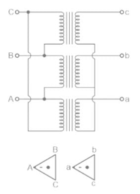
- The ratio of transformation between primary and secondary line voltage is exactly the same as that of each transformer.
- Further, the secondary voltage triangle abc occupies the same relative position as the primary voltage triangle ABC i.e. there is no angular displacement between the two.
- Moreover, there is no internal phase shift between phase and line voltages on either side as was the case in Y − Y connection.
This connection has the following advantages:
- In order that the output voltage is sinusoidal, it is necessary that the magnetizing current of the transformer must contain a third harmonic component. In this case, the third harmonic component of the magnetizing current can flow in the ∆-connected transformer primaries without flowing in the line wires. The three phases are 120° apart which is 3 × 120 = 360° with respect to the third harmonic, hence it merely circulates in the ∆. Therefore, the flux is sinusoidal which results in sinusoidal voltages.
- No difficulty is experienced from unbalanced loading as was the case in Y − Y connection. The three-phase voltages remain practically constant regardless of load imbalance.
- If one transformer becomes disabled, the system can continue to operate in open-delta or in V − V although with reduced available capacity. The reduced capacity is 58% and not 66.7% of the normal value.
There is a phase difference of______ between the corresponding phases of primary and secondary______ in a star/delta transformer.- a)30 degrees, Voltage
- b)60 degrees, Voltage
- c)Zero degree, Current
- d)45 degrees, Current
Correct answer is option 'A'. Can you explain this answer?
There is a phase difference of______ between the corresponding phases of primary and secondary______ in a star/delta transformer.
a)
30 degrees, Voltage
b)
60 degrees, Voltage
c)
Zero degree, Current
d)
45 degrees, Current
| | Vibhor Goyal answered |
Star-Delta transformer:
- Consider a 3-phase star-delta transformer with primary side Y connected (star connected) and secondary side with delta connected as shown below
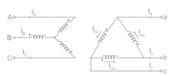
- The polarity markings are indicated on each phase.
- The dots on the winding indicate the terminals which are positive at the same time on the undotted terminals.
- Phase on star side – A, B, C
- Phase on delta side – a, b, c
- The labeling is indicated to the diagram corresponding to +90° connections in which the positive sequences on the delta side are lead by 90° corresponding to the star side.
- Thus the line current flows through the phase and A.
- If we label delta as b → a, c → b, and a → c. There we will get standard Yd1, –30° connection
- If polarities on the delta side are also reversed, we get standard Yd11, 30° connection as shown in the figure given below.
- Thus we can get a phase difference of 30° between input and output of three-phase transformer by using a star-delta connection.
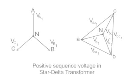
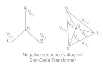
Important Points:
The phase shift in different connections of transformer are given below.
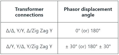
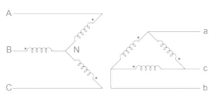
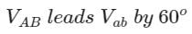
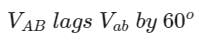
Chapter doubts & questions for Three-Phase Transformers - Electrical Machines for Electrical Engg. 2026 is part of Electrical Engineering (EE) exam preparation. The chapters have been prepared according to the Electrical Engineering (EE) exam syllabus. The Chapter doubts & questions, notes, tests & MCQs are made for Electrical Engineering (EE) 2026 Exam. Find important definitions, questions, notes, meanings, examples, exercises, MCQs and online tests here.
Chapter doubts & questions of Three-Phase Transformers - Electrical Machines for Electrical Engg. in English & Hindi are available as part of Electrical Engineering (EE) exam. Download more important topics, notes, lectures and mock test series for Electrical Engineering (EE) Exam by signing up for free.
Electrical Machines for Electrical Engg.35 videos|96 docs|42 tests |