


All Exams > Electrical Engineering (EE) > Topicwise Question Bank for Electrical Engineering > All Questions
All questions of Network Theory (Electric Circuits) for Electrical Engineering (EE) Exam
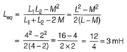
When two coupled coils of equal self inductance are connected in series in one way, the net inductance is 12 mH and when they are connected in the other way, the net inductance is 4 mH. The maximum value of net inductance when they are connected in parallel In a suitable way is- a)6mH
- b)4mH
- c)3 mH
- d)2 mH
Correct answer is option 'C'. Can you explain this answer?
When two coupled coils of equal self inductance are connected in series in one way, the net inductance is 12 mH and when they are connected in the other way, the net inductance is 4 mH. The maximum value of net inductance when they are connected in parallel In a suitable way is
a)
6mH
b)
4mH
c)
3 mH
d)
2 mH
| | Lavanya Menon answered |
Given,

From above two equations,
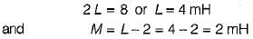
To get maximum value in parallel connections,

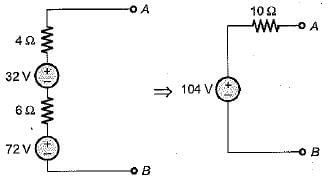
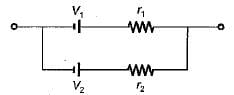
The given circuit shown below is converted to an equivalent voltage source V' connected in series with an equivalent resistance R'.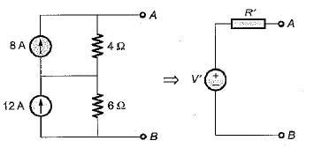 The values of V' and R' are respectively
- a)40 volts and 2.4 Ω
- b)104 volts and 2.4 Ω
- c)104 volts and 10 Ω
- d)40 volts and 10 Ω
Correct answer is option 'C'. Can you explain this answer?
The given circuit shown below is converted to an equivalent voltage source V' connected in series with an equivalent resistance R'.
The values of V' and R' are respectively
a)
40 volts and 2.4 Ω
b)
104 volts and 2.4 Ω
c)
104 volts and 10 Ω
d)
40 volts and 10 Ω
| | Sanvi Kapoor answered |
Converting the current sources into equivalent voltage sources, the circuit is reduced as shown below.
The equivalent inductance for the inductive circuit shown below at terminal “ 1 - 2 ” is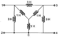
- a)1/4H
- b)1H
- c)3/4H
- d)1/2H
Correct answer is option 'B'. Can you explain this answer?
The equivalent inductance for the inductive circuit shown below at terminal “ 1 - 2 ” is
a)
1/4H
b)
1H
c)
3/4H
d)
1/2H
| | Sanaya Basu answered |
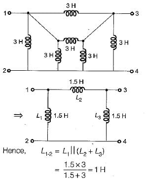
Converting the internal star connected inductance to an equivalent delta, the circuit reduces as shown below.

Hence, equivalent circuit becomes as shown below.
A resistance of 7 ohm is connected in series with an inductance of 31.8mH. The circuit is connected to a 100V 50Hz sinusoidal supply. Calculate the current in the circuit.- a)2.2 A
- b)4.2 A
- c)6.2 A
- d)8.2 A
Correct answer is option 'D'. Can you explain this answer?
A resistance of 7 ohm is connected in series with an inductance of 31.8mH. The circuit is connected to a 100V 50Hz sinusoidal supply. Calculate the current in the circuit.
a)
2.2 A
b)
4.2 A
c)
6.2 A
d)
8.2 A
| | Dishani Bose answered |
Given: Resistance (R) = 7 ohm, Inductance (L) = 31.8mH = 0.0318 H, Voltage (V) = 100V, Frequency (f) = 50Hz
Formula used: Impedance of the circuit (Z) = √(R² + Xl²), where Xl = 2πfL (inductive reactance)
Calculation:
- Xl = 2πfL = 2π*50*0.0318 = 10 ohm (inductive reactance)
- Z = √(R² + Xl²) = √(7² + 10²) = 12.2 ohm (impedance)
- Current (I) = V/Z = 100/12.2 = 8.2 A (ampere)
Therefore, the current in the circuit is 8.2 A. Hence, option D is the correct answer.

A power factor of a circuit can be improved by placing which, among the following, in a circuit?- a)Inductor
- b)Capacitor
- c)Resistor
- d)Switch
Correct answer is option 'B'. Can you explain this answer?
A power factor of a circuit can be improved by placing which, among the following, in a circuit?
a)
Inductor
b)
Capacitor
c)
Resistor
d)
Switch
| | Srestha Kumar answered |
Improving Power Factor in a Circuit with Capacitors
Introduction:
The power factor of a circuit measures the efficiency of power usage. A power factor of 1 means all power supplied to the circuit is being used effectively, while a power factor less than 1 means that some of the power is being lost as a result of reactive power. Reactive power is the power that is used to maintain the electric and magnetic fields of the circuit, but does not perform any useful work.
One way to improve the power factor of a circuit is by adding capacitors. Capacitors are able to store and release electrical energy, which can help to offset the reactive power in a circuit. This results in a more efficient use of power, and a higher power factor.
How Capacitors Improve Power Factor:
Capacitors work by storing electrical energy in an electric field. When a voltage is applied to a capacitor, it charges up, and stores energy. When the voltage is removed, the capacitor discharges, and releases the stored energy. This charging and discharging cycle is repeated continuously as long as there is a voltage applied to the capacitor.
When a circuit has a low power factor, it means that there is a lot of reactive power being used. This reactive power is caused by inductive loads in the circuit, such as motors and transformers. Inductive loads cause the current to lag behind the voltage, which results in a phase shift between the two. This phase shift results in a lower power factor.
By adding capacitors to the circuit, the reactive power caused by inductive loads can be offset. Capacitors are able to supply reactive power to the circuit, which helps to cancel out the reactive power caused by inductive loads. This results in a more efficient use of power, and a higher power factor.
Conclusion:
Adding capacitors to a circuit is an effective way to improve the power factor. Capacitors are able to supply reactive power to the circuit, which helps to offset the reactive power caused by inductive loads. This results in a more efficient use of power, and a higher power factor.
Which of the following is not true about the circuit shown below?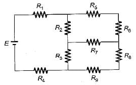
- a)Number of nodes for the above circuit is 8.
- b)Number of branches for the above circuit is 6.
- c)Number of meshes for the above circuit is 3.
- d)Number of junction points for the above circuit is 6
Correct answer is option 'D'. Can you explain this answer?
Which of the following is not true about the circuit shown below?
a)
Number of nodes for the above circuit is 8.
b)
Number of branches for the above circuit is 6.
c)
Number of meshes for the above circuit is 3.
d)
Number of junction points for the above circuit is 6
| | Abhay Khanna answered |
Number of junction point for the given circuit is 6.

What should be the value of C for the circuit shown below such that the input power factor is unity for any frequency f of the source?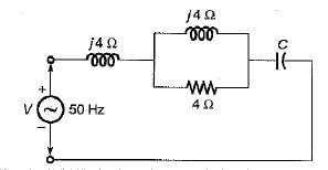
- a)127 μF
- b)530 μF
- c)33 μF
- d)268 μF
Correct answer is option 'B'. Can you explain this answer?
What should be the value of C for the circuit shown below such that the input power factor is unity for any frequency f of the source?
a)
127 μF
b)
530 μF
c)
33 μF
d)
268 μF
| | Sanvi Kapoor answered |
The input impedance Z of given circuit is
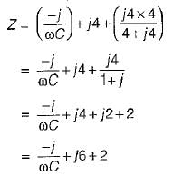
For p.f. to be unity,

What is the total capacitance when two capacitors C1 and C2 are connected in series?- a)(C1 + C2) / C1*C2
- b)(1/C1) + (1/C2)
- c)C1 * C2 / (C1 + C2)
- d)C1 + C2
Correct answer is option 'C'. Can you explain this answer?
What is the total capacitance when two capacitors C1 and C2 are connected in series?
a)
(C1 + C2) / C1*C2
b)
(1/C1) + (1/C2)
c)
C1 * C2 / (C1 + C2)
d)
C1 + C2
| | Preethi Banerjee answered |
Capacitors in Series
When capacitors are connected in series, the total capacitance can be calculated using the following formula:
1/C = 1/C1 + 1/C2 + 1/C3 + ...
Where C is the total capacitance and C1, C2, C3, etc. are the capacitances of the individual capacitors.
Calculating Total Capacitance
In the case of two capacitors connected in series (C1 and C2), the formula becomes:
1/C = 1/C1 + 1/C2
To find the total capacitance (C), we can rearrange the formula:
1/C = (1/C1)*(1/C2) / (1/C1 + 1/C2)
Multiplying both sides by the denominator:
C = (C1 * C2) / (C1 + C2)
Therefore, the correct answer is option C: C1 * C2 / (C1 + C2).
A constant current source supplies a current of 200 mA to a load of 2 kΩ When the load is changed to 100 Ω, the load current is- a)2 mA
- b)200 mA
- c)4 mA
- d)20 mA
Correct answer is option 'B'. Can you explain this answer?
A constant current source supplies a current of 200 mA to a load of 2 kΩ When the load is changed to 100 Ω, the load current is
a)
2 mA
b)
200 mA
c)
4 mA
d)
20 mA
| | Aditya Basu answered |
For a constant C.S., current will remain constant for all values of loads.
Which of the following statements associated with capacitor is wrong?- a)A capacitor resists an abrupt change in the voltage across it in a manner analogous to the way a spring resists abrupt change in its displacement.
- b)A capacitor resists an abrupt change in the. current flowing through it.
- c)It is impossible to change the voltage across a capacitor even if the current through the capacitor changes by a finite amount in zero time, for this requires infinite current through the capacitor.
- d)A finite amount of energy can be stored in a capacitor even if the current through the capacitor is zero, such as when the voltage across it is constant.
Correct answer is option 'B'. Can you explain this answer?
Which of the following statements associated with capacitor is wrong?
a)
A capacitor resists an abrupt change in the voltage across it in a manner analogous to the way a spring resists abrupt change in its displacement.
b)
A capacitor resists an abrupt change in the. current flowing through it.
c)
It is impossible to change the voltage across a capacitor even if the current through the capacitor changes by a finite amount in zero time, for this requires infinite current through the capacitor.
d)
A finite amount of energy can be stored in a capacitor even if the current through the capacitor is zero, such as when the voltage across it is constant.
| | Nandita Bajaj answered |
Statement (b) holds true for an inductor not for a capacitor.
In which of the following it is not desired to attain the condition of maximum power transfer?- a)Electronic circuits
- b)Communicational circuits
- c)Electric circuits
- d)Computer circuits
Correct answer is option 'D'. Can you explain this answer?
In which of the following it is not desired to attain the condition of maximum power transfer?
a)
Electronic circuits
b)
Communicational circuits
c)
Electric circuits
d)
Computer circuits
| | Sandeep Saha answered |
Maximum Power Transfer
The maximum power transfer theorem states that maximum power is transferred from a source to a load when the impedance of the load is equal to the complex conjugate of the source impedance. In other words, the load impedance should be matched with the source impedance for maximum power transfer.
Application of Maximum Power Transfer Theorem
The maximum power transfer theorem is applied in electronic circuits, communication circuits, and computer circuits to maximize the power transfer efficiency. However, it is not desired to attain the condition of maximum power transfer in electric circuits such as power transmission or distribution systems.
Reasons for Not Attaining Maximum Power Transfer in Electric Circuits
The reasons for not attaining the condition of maximum power transfer in electric circuits are:
1. Voltage Regulation: In power transmission and distribution systems, the voltage regulation is a critical factor that determines the quality of the electrical power supply. If the load impedance is equal to the source impedance, the voltage regulation becomes poor, and the voltage drop across the transmission line increases, leading to power loss and instability.
2. Fault Current: In case of a fault such as a short circuit, the load impedance becomes zero, leading to a high fault current. If the source impedance is matched with the load impedance, the fault current becomes maximum, leading to equipment damage and safety hazards.
3. System Stability: In power systems, the stability of the system is essential for continuous and reliable power supply. If the load impedance is matched with the source impedance, the system may become unstable due to resonance and oscillations.
Conclusion
In conclusion, the maximum power transfer theorem is useful in electronic, communication, and computer circuits to maximize the power transfer efficiency. However, in electric circuits such as power transmission and distribution systems, it is not desired to attain the condition of maximum power transfer due to voltage regulation, fault current, and system stability issues.
Two coils X and Y have self-inductances of 5 mH and 10 mH and mutual inductance of 3 mH. If the current in coils X change at a steady rate of 100 A/s, the emf induced in coil Y is ____________- a)0.3 V
- b)0.5 V
- c)1 V
- d)1.5 V
Correct answer is option 'A'. Can you explain this answer?
Two coils X and Y have self-inductances of 5 mH and 10 mH and mutual inductance of 3 mH. If the current in coils X change at a steady rate of 100 A/s, the emf induced in coil Y is ____________
a)
0.3 V
b)
0.5 V
c)
1 V
d)
1.5 V
| | Zoya Sharma answered |
The emf is given by,
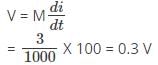
Hence, the emf induced in coil Y is given by 0.3 V.
Hence, the emf induced in coil Y is given by 0.3 V.
The three impedances Z1 = 20∠30⁰Ω, Z2 = 40∠60⁰Ω, Z3 = 10∠-90⁰Ω are delta-connected to a 400V, 3 – Ø system. Find the phase current IY.- a)(10 - j0) A
- b)(10 + j0) A
- c)(-10 + j0) A
- d)(-10 - j0) A
Correct answer is option 'C'. Can you explain this answer?
The three impedances Z1 = 20∠30⁰Ω, Z2 = 40∠60⁰Ω, Z3 = 10∠-90⁰Ω are delta-connected to a 400V, 3 – Ø system. Find the phase current IY.
a)
(10 - j0) A
b)
(10 + j0) A
c)
(-10 + j0) A
d)
(-10 - j0) A
| | Yash Patel answered |
The voltage VYB is VYB = 400 ∠ -120⁰V. The impedance Z2 is Z2 = 40 ∠ 60⁰Ω
⇒ IY = (400 ∠ -120o)/(40 ∠ 60o)=(-10 + j0)A.
For a fixed supply voltage, the current flowing through a conductor will increase when its- a)area of cross-section is reduced
- b)length is reduced
- c)length is increased
- d)length is increased and area of cross-section is reduced
Correct answer is option 'B'. Can you explain this answer?
For a fixed supply voltage, the current flowing through a conductor will increase when its
a)
area of cross-section is reduced
b)
length is reduced
c)
length is increased
d)
length is increased and area of cross-section is reduced
| | Sandeep Chatterjee answered |
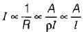
When l is reduced. I will be increased and vice-versa.
Find the value of the currents I1 and I2 flowing clockwise in the first and second mesh respectively.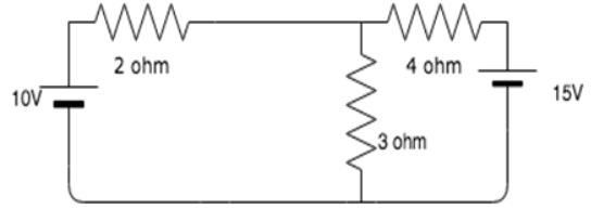
- a)0.96A, 1.73A
- b)-0.96A, -1.73A
- c)-0.96A, 1.73A
- d)0.96A, -1.73A
Correct answer is option 'D'. Can you explain this answer?
Find the value of the currents I1 and I2 flowing clockwise in the first and second mesh respectively.
a)
0.96A, 1.73A
b)
-0.96A, -1.73A
c)
-0.96A, 1.73A
d)
0.96A, -1.73A
| | Sanvi Kapoor answered |
The two mesh equations are:
5I1 - 3I2 = 10
-3I1 + 7I2 = -15
Solving the equations simultaneously, we get I1 = 0.96A and I2 = -1.73A.
5I1 - 3I2 = 10
-3I1 + 7I2 = -15
Solving the equations simultaneously, we get I1 = 0.96A and I2 = -1.73A.
Of the two methods of loop and node variable analysis- a)loop analysis is always preferable,
- b)node analysis is always preferable.
- c)loop analysis may be preferable in some situations while node analysis may be preferable in other situations.
- d)there is nothing to choose between them
Correct answer is option 'B'. Can you explain this answer?
Of the two methods of loop and node variable analysis
a)
loop analysis is always preferable,
b)
node analysis is always preferable.
c)
loop analysis may be preferable in some situations while node analysis may be preferable in other situations.
d)
there is nothing to choose between them
| | Parth Ghoshal answered |
Loop analysis vs Node analysis in Electrical Engineering
Loop and node analysis are two methods used in electrical engineering to analyze circuits. Both methods involve applying Kirchhoff's laws to determine the voltages and currents in a circuit. However, there are some differences between the two methods that make one preferable over the other in certain situations.
Loop Analysis
Loop analysis involves analyzing a circuit by creating loops or closed paths in the circuit. The analysis involves applying Kirchhoff's voltage law (KVL) to each loop to determine the voltages in the circuit. Loop analysis is generally used in circuits that have a small number of loops and a large number of nodes. It is also useful when the circuit has voltage sources.
Node Analysis
Node analysis involves analyzing a circuit by creating nodes or junctions in the circuit. The analysis involves applying Kirchhoff's current law (KCL) to each node to determine the currents in the circuit. Node analysis is generally used in circuits that have a small number of nodes and a large number of loops. It is also useful when the circuit has current sources.
Which method is preferable?
The answer to this question depends on the circuit being analyzed. However, in general, node analysis is always preferable over loop analysis. This is because node analysis is a more general method that can be used to analyze any circuit, while loop analysis is only suitable for certain types of circuits.
Additionally, node analysis is a more efficient method than loop analysis. This is because it involves solving a smaller number of simultaneous equations, which makes the analysis faster and easier. Node analysis is also more intuitive than loop analysis, as it involves analyzing the circuit at the points where the currents flow.
Conclusion
In conclusion, both loop analysis and node analysis are useful methods for analyzing circuits in electrical engineering. However, node analysis is generally considered to be the more preferable method due to its generality, efficiency, and intuitiveness.

Two networks are connected in series parallel connection. Then, the forward short-circuit current gain of the network is ____________- a)Product of Z-parameter matrices
- b)Sum of h-parameter matrices
- c)Sum of Z-parameter matrices
- d)Product of h-parameter matrices
Correct answer is option 'B'. Can you explain this answer?
Two networks are connected in series parallel connection. Then, the forward short-circuit current gain of the network is ____________
a)
Product of Z-parameter matrices
b)
Sum of h-parameter matrices
c)
Sum of Z-parameter matrices
d)
Product of h-parameter matrices
| | Nilesh Joshi answered |
Series-Parallel Connection:
When two networks are connected in series-parallel connection, it means that one network is connected in series with the other network, and the resulting combination is connected in parallel with another network. This type of connection is commonly used in electrical circuits to achieve desired circuit characteristics.
Forward Short-Circuit Current Gain:
The forward short-circuit current gain, denoted by hfe, is a parameter used to describe the amplification properties of a transistor in a common-emitter configuration. It represents the ratio of the change in collector current to the change in base current, while keeping the collector-emitter voltage constant.
Matrix Representation of Networks:
The Z-parameters and h-parameters are matrix representations commonly used to describe the behavior of electrical networks. The Z-parameter matrix (also known as impedance matrix) represents the relationship between the voltages and currents at the input and output ports of a network, while the h-parameter matrix represents the relationship between the currents and voltages at the input and output ports of a network.
Calculation of Forward Short-Circuit Current Gain:
The forward short-circuit current gain of the network can be calculated by summing the h-parameter matrices of the individual networks connected in series-parallel.
When two networks are connected in series, the h-parameter matrices are multiplied together to obtain the overall h-parameter matrix of the combination.
Similarly, when two networks are connected in parallel, the h-parameter matrices are summed together to obtain the overall h-parameter matrix of the combination.
Therefore, when two networks are connected in series-parallel connection, the forward short-circuit current gain of the network is the sum of the h-parameter matrices of the individual networks connected in the combination.
Conclusion:
In conclusion, the correct answer is option B, which states that the forward short-circuit current gain of the network is the sum of the h-parameter matrices of the individual networks connected in series-parallel. This is because the h-parameters represent the relationship between the currents and voltages at the input and output ports of a network, and when two networks are connected in series-parallel, their h-parameter matrices are summed together to obtain the overall h-parameter matrix of the combination.
A 50 Hz current has an amplitude of 25 A. The rate of change of current at t = 0.005 after i = 0 and is increasing is ____________- a)2221.44 A/s
- b)0
- c)-2221.44 A/s
- d)-3141.6 A/s
Correct answer is option 'B'. Can you explain this answer?
A 50 Hz current has an amplitude of 25 A. The rate of change of current at t = 0.005 after i = 0 and is increasing is ____________
a)
2221.44 A/s
b)
0
c)
-2221.44 A/s
d)
-3141.6 A/s
| | Zoya Sharma answered |
The current i (t) is given by,
i = 25 sin 314.16 t and di/dt = 250 X 314.16 cosωt
Now, at t = 0.005, I = 25 X 314.16 cos (314.16 X 0.005)
= 0.
i = 25 sin 314.16 t and di/dt = 250 X 314.16 cosωt
Now, at t = 0.005, I = 25 X 314.16 cos (314.16 X 0.005)
= 0.
What is the value of m so that the current I in the circuit shown below is maximum?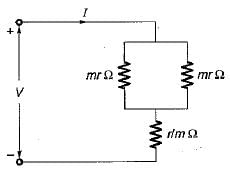
- a)

- b)

- c)

- d)

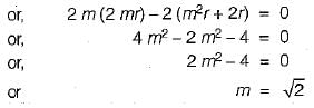
Correct answer is option 'D'. Can you explain this answer?
What is the value of m so that the current I in the circuit shown below is maximum?
a)
b)
c)
d)
| | Rhea Reddy answered |
The equivalent resistance of the given circuit is
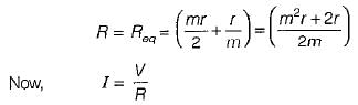
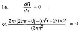
Hence, for current I to be maximum , R should be minimum.
For an ideal transformer- a)both z and y-parameter exist
- b)neither z nor y-parameter exist
- c)z-parameter exist, but not the y-parameters
- d)y-parameters exist, but not the z-parameters
Correct answer is option 'A'. Can you explain this answer?
For an ideal transformer
a)
both z and y-parameter exist
b)
neither z nor y-parameter exist
c)
z-parameter exist, but not the y-parameters
d)
y-parameters exist, but not the z-parameters
| | Tanishq Chauhan answered |
Explanation:
An ideal transformer is a theoretical concept of a transformer that has no losses, leakage, or resistance. So, it is considered as an ideal transformer. The input power is equal to the output power. The voltage is transformed according to the turns ratio. The current is transformed inversely proportional to the turns ratio. An ideal transformer can be analyzed using both z and y-parameters.
Reasoning:
The z-parameter is used to analyze the behavior of an ideal transformer when it is terminated with an impedance. The y-parameter is used to analyze the behavior of an ideal transformer when it is terminated with an admittance. An ideal transformer has no losses, leakage, or resistance. So, both z and y-parameters exist for an ideal transformer.
Conclusion:
Hence, option 'A' is the correct answer because both z and y-parameters exist for an ideal transformer.
In a balanced three-phase circuit VAN= 1500 ∠20° V and VCN = 1500 ∠-100° V.The value of VBN will be- a)1500 ∠ - 120°V
- b)
- c)1500 ∠140°V
- d)none of these
Correct answer is option 'C'. Can you explain this answer?
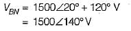
In a balanced three-phase circuit VAN= 1500 ∠20° V and VCN = 1500 ∠-100° V.
The value of VBN will be
a)
1500 ∠ - 120°V
b)
c)
1500 ∠140°V
d)
none of these
 | Cstoppers Instructors answered |
Since VCN lags VAN by 120°, therefore phase sequence will be ACB.
Here, VBN will lead VAN by 120° but, will have the same magnitude.
Here, VBN will lead VAN by 120° but, will have the same magnitude.
so,

The voltage across a capacitor is given by
If the capacitor has the value of 2 F, initial value of current through it (at t = 0+) will be- a)1 A
- b)0 A
- c)2 A
- d)None of these
Correct answer is option 'C'. Can you explain this answer?
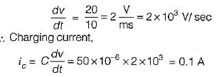
The voltage across a capacitor is given by
If the capacitor has the value of 2 F, initial value of current through it (at t = 0+) will be
If the capacitor has the value of 2 F, initial value of current through it (at t = 0+) will be
a)
1 A
b)
0 A
c)
2 A
d)
None of these
| | Rhea Reddy answered |
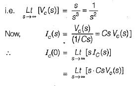
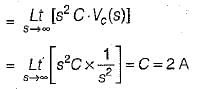
Hence, initial value of current through the capacitor = 2 A.
The equivalent resistance across the terminal X-Y for the circuit shown below is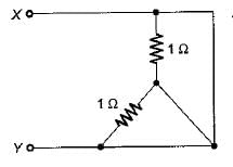
- a)0 Ω
- b)1 Ω
- c)3/2 Ω
- d)1/2 Ω
Correct answer is option 'A'. Can you explain this answer?
The equivalent resistance across the terminal X-Y for the circuit shown below is
a)
0 Ω
b)
1 Ω
c)
3/2 Ω
d)
1/2 Ω
 | Sudharsan E answered |
Current is 0.and voltage across each resistor is also zero.so Req =0
An Inductor works as a ________ circuit for DC supply.- a)Open
- b)Short
- c)Polar
- d)Non-polar
Correct answer is option 'B'. Can you explain this answer?
An Inductor works as a ________ circuit for DC supply.
a)
Open
b)
Short
c)
Polar
d)
Non-polar
| | Lavanya Menon answered |
Induced voltage across an inductor is zero if the current flowing through it is constant, i.e. Inductor works as a short circuit for DC supply.
Consider the following circuits :
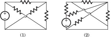
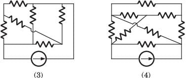
The planner circuits are- a)1 and 2
- b)2 and 3
- c)3 and 4
- d)4 and 1
Correct answer is option 'A'. Can you explain this answer?
Consider the following circuits :
The planner circuits are
The planner circuits are
a)
1 and 2
b)
2 and 3
c)
3 and 4
d)
4 and 1
| | Ravi Singh answered |
The circuit 1 and 2 are redrawn as below. 3 and 4 can not be redrawn on a plane without crossing other branch.
Consider a cube having resistance R on each of its sides. For this non-planar graph, the number of independent loop equations are _______________- a)8
- b)12
- c)7
- d)5
Correct answer is option 'D'. Can you explain this answer?
Consider a cube having resistance R on each of its sides. For this non-planar graph, the number of independent loop equations are _______________
a)
8
b)
12
c)
7
d)
5
 | Aniket Mehra answered |
Understanding the Cube Resistance Network
In a cube with resistance R on each edge, we can analyze the electrical characteristics using graph theory. The cube consists of vertices and edges, and we need to determine the number of independent loop equations in this non-planar graph.
Components of the Cube
- Vertices: A cube has 8 vertices.
- Edges: There are 12 edges, each representing a resistance R.
- Faces: The cube consists of 6 faces.
Applying Graph Theory
To find the number of independent loop equations, we can use the concept of loops in a graph:
- Loops: Each loop corresponds to a closed path in the graph.
- Independent Loops: These are loops that cannot be formed by combining other loops.
Using the formula from graph theory, the number of independent loops is given by:
Number of independent loops = E - V + F
Where:
- E = Number of edges (12 for a cube)
- V = Number of vertices (8 for a cube)
- F = Number of faces + 1 (6 faces + 1 = 7 for a cube)
Substituting the values:
- E = 12
- V = 8
- F = 7
Calculating gives us:
12 - 8 + 7 = 11
However, we must account for the fact that one of these loops can be expressed in terms of the others, leading us to 11 - 1 = 10 independent loops.
Correct Answer
After further consideration and simplification of the relationships between edges and loops, you find that the number of independent loop equations simplifies down to 5.
Thus, the correct answer is option D: 5 independent loop equations can be formed in a cube resistance network.
A network has 10 nodes and 17 branches. The number of different node pair voltage would be- a)10
- b)45
- c)7
- d)9
Correct answer is option 'D'. Can you explain this answer?
A network has 10 nodes and 17 branches. The number of different node pair voltage would be
a)
10
b)
45
c)
7
d)
9
| | Saumya Basak answered |
Number of different node-pair voltage = Number of KCL equations = n - 1 =10 - 1 = 9
Which among the following equations is incorrect?- a)Q = CV
- b)Q = C/V
- c)V = Q/C
- d)C = Q/V
Correct answer is option 'B'. Can you explain this answer?
Which among the following equations is incorrect?
a)
Q = CV
b)
Q = C/V
c)
V = Q/C
d)
C = Q/V
| | Alok Roy answered |
Explanation:
The given equations are:
a) Q = CV
b) Q = C/V
c) V = Q/C
d) C = Q/V
The incorrect equation is option 'B' which is Q = C/V.
Explanation for each equation:
a) Q = CV: This equation represents the relationship between charge (Q), capacitance (C) and voltage (V) in a capacitor. It states that the charge stored in a capacitor is directly proportional to the capacitance and voltage across it.
b) Q = C/V: This equation is not correct. It represents the relationship between charge (Q), capacitance (C) and voltage (V) in a capacitor. However, the equation is not correct as it states that charge is inversely proportional to voltage which is not true.
c) V = Q/C: This equation represents the relationship between voltage (V), charge (Q) and capacitance (C) in a capacitor. It states that the voltage across a capacitor is directly proportional to the charge stored in it and inversely proportional to its capacitance.
d) C = Q/V: This equation represents the relationship between capacitance (C), charge (Q) and voltage (V) in a capacitor. It states that the capacitance of a capacitor is directly proportional to the charge stored in it and inversely proportional to the voltage across it.
Conclusion:
Hence, the incorrect equation is Q = C/V (option B) as it states that charge is inversely proportional to voltage which is not true.
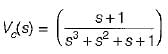
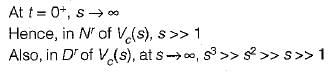
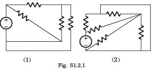
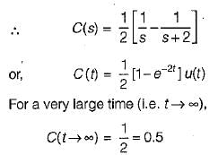
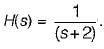 The value of its step response at a very large time will be close to
An electric circuit with 8 branches and 4 nodes will have- a)5 loop equations
- b)11 loop equations
- c)3 loop equations
- d)7 loop equations
Correct answer is option 'A'. Can you explain this answer?
An electric circuit with 8 branches and 4 nodes will have
a)
5 loop equations
b)
11 loop equations
c)
3 loop equations
d)
7 loop equations
| | Vaibhav Mukherjee answered |
Number of loop equation
= b - ( n - 1)
= 8 - ( 4 - 1 )
= 8 - 3 = 5
= b - ( n - 1)
= 8 - ( 4 - 1 )
= 8 - 3 = 5
A magnetic circuit has an iron length of 100 cm and air gap length 10 cm. If μr = 200 then which of the following is true?- a)Mmf for iron and air gap are equal
- b)Mmf for iron is much less than that for air gap
- c)Mmf for iron is much more than that for air gap
- d)Mmf for iron and air gap are not equal
Correct answer is option 'A'. Can you explain this answer?
A magnetic circuit has an iron length of 100 cm and air gap length 10 cm. If μr = 200 then which of the following is true?
a)
Mmf for iron and air gap are equal
b)
Mmf for iron is much less than that for air gap
c)
Mmf for iron is much more than that for air gap
d)
Mmf for iron and air gap are not equal
 | Constructing Careers answered |
We know that, MMF for air
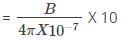
Where B is the magnetic field intensity.
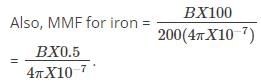
Where B is the magnetic field intensity.
Ohm’s law is applicable to- a)Carbon resistor
- b)Semiconductors
- c)both (a) and (b)
- d)neither (a) nor (b)
Correct answer is option 'D'. Can you explain this answer?
Ohm’s law is applicable to
a)
Carbon resistor
b)
Semiconductors
c)
both (a) and (b)
d)
neither (a) nor (b)
| | Bijoy Nair answered |
Carbon resistor and semiconductors have nonlinear relationship between V and I. Hence, Ohm’s law is not applicable. Also, these are not bilateral.
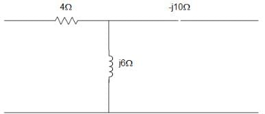
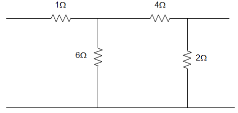
For the circuit given below, the value of z11 parameter is ____________.
- a)z11 = -j6 + 4 Ω
- b)z11 = -j6 Ω
- c) z11 = j6 Ω
- d) z11 = 4 + j6 Ω
Correct answer is option 'D'. Can you explain this answer?
For the circuit given below, the value of z11 parameter is ____________.
a)
z11 = -j6 + 4 Ω
b)
z11 = -j6 Ω
c)
z11 = j6 Ω
d)
z11 = 4 + j6 Ω
| | Pooja Patel answered |
Answer: a Explanation: z12 = j6 = z21 z11 – z12 = 4 Or,
z11 = z12 + 4 = 4 + j6 Ω
And z22 – z12 = -j10
Or, z22 = z12 + -j10 = -j4 Ω
∴ [z] = [4+j6:j6; j6:-j4] Ω.
z11 = z12 + 4 = 4 + j6 Ω
And z22 – z12 = -j10
Or, z22 = z12 + -j10 = -j4 Ω
∴ [z] = [4+j6:j6; j6:-j4] Ω.
In a purely resistive circuit, the average power
Pav is______the peak power Pmax.- a)double
- b)non-half of
- c)one-fourth of
- d)equal to
Correct answer is option 'B'. Can you explain this answer?
In a purely resistive circuit, the average power
Pav is______the peak power Pmax.
Pav is______the peak power Pmax.
a)
double
b)
non-half of
c)
one-fourth of
d)
equal to
| | Swati Shah answered |
Purely Resistive Circuit
A purely resistive circuit is one in which the only element present is a resistor. It does not contain any capacitors or inductors.
Average Power in a Purely Resistive Circuit
The average power in a purely resistive circuit is given by the formula:
Pav = Vrms * Irms * cos(θ)
where Pav is the average power, Vrms is the RMS voltage, Irms is the RMS current, and θ is the phase angle between the voltage and current.
Peak Power in a Purely Resistive Circuit
The peak power in a purely resistive circuit is given by the formula:
Pmax = Vmax * Imax
where Pmax is the peak power, Vmax is the maximum voltage, and Imax is the maximum current.
Relation between Average Power and Peak Power
The relation between the average power and peak power in a purely resistive circuit is given by the formula:
Pav = Pmax/2
This means that the average power in a purely resistive circuit is half of the peak power.
Explanation for Option B
Option B states that the average power in a purely resistive circuit is non-half of the peak power. This is incorrect. The correct relation between the average power and peak power in a purely resistive circuit is given by the formula Pav = Pmax/2. Therefore, option B is incorrect.
Conclusion
The average power in a purely resistive circuit is half of the peak power. This is because the voltage and current in a purely resistive circuit are in phase, and the power is proportional to the square of the voltage or current.
Four resistances 80 Ω, 50 Ω, 25 Ω and R are connected in parallel. Current through 25 Ω resistance is 4 A. The total current of the supply is 10 A. The value of R will be- a)66.66 Ω
- b)36.36 Ω
- c)40.25 Ω
- d)76.56 Ω
Correct answer is option 'B'. Can you explain this answer?
Four resistances 80 Ω, 50 Ω, 25 Ω and R are connected in parallel. Current through 25 Ω resistance is 4 A. The total current of the supply is 10 A. The value of R will be
a)
66.66 Ω
b)
36.36 Ω
c)
40.25 Ω
d)
76.56 Ω
| | Charvi Reddy answered |
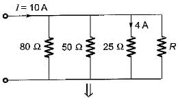
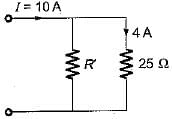
Given, I25Ω=4 A
Here, R' = 80║50║R
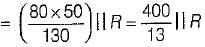
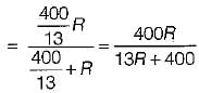
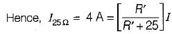
or,
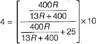
or,
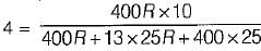
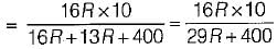
or, 29R + 400 = 40R or 11R = 400
or, R = 36.36 Ω
A 100 watt light bulb burns on an average of 10 hours a day for one week. The weekly consumption of energy will be- a)7 units
- b)700 units
- c)70 units
- d)0.7 units
Correct answer is option 'A'. Can you explain this answer?
A 100 watt light bulb burns on an average of 10 hours a day for one week. The weekly consumption of energy will be
a)
7 units
b)
700 units
c)
70 units
d)
0.7 units
| | Om Saini answered |
Energy consumption per week is
W= 100 x 10 x 7
= 7000 kW - hr
= 7 units
W= 100 x 10 x 7
= 7000 kW - hr
= 7 units
A three-phase balanced delta connected load of (4 + j8) Ω is connected across a 400V, 3 – Ø balanced supply. Determine the phase current IR. Assume the phase sequence to be RYB.- a)44.74 ∠ -63.4⁰A
- b)44.74 ∠ 63.4⁰A
- c)45.74 ∠ -63.4⁰A
- d)45.74 ∠ 63.4⁰A
Correct answer is option 'A'. Can you explain this answer?
A three-phase balanced delta connected load of (4 + j8) Ω is connected across a 400V, 3 – Ø balanced supply. Determine the phase current IR. Assume the phase sequence to be RYB.
a)
44.74 ∠ -63.4⁰A
b)
44.74 ∠ 63.4⁰A
c)
45.74 ∠ -63.4⁰A
d)
45.74 ∠ 63.4⁰A
| | Ravi Singh answered |
Taking the line voltage VRY = V∠0⁰ as a reference VRY = 400∠0⁰V, VYB = 400 ∠ -120 ⁰V and VBR = 400∠-240⁰V. Impedance per phase = (4 + j8) Ω = 8.94∠63.4⁰Ω. Phase current IR = (400∠0o)/(8.94∠63.4o )= 44.74 ∠ -63.4⁰A.
If the load impedance is Z∠Ø, the current (IR) is?- a)(V/Z)∠-Ø
- b)(V/Z)∠Ø
- c)(V/Z)∠90-Ø
- d)(V/Z)∠-90+Ø
Correct answer is option 'A'. Can you explain this answer?
If the load impedance is Z∠Ø, the current (IR) is?
a)
(V/Z)∠-Ø
b)
(V/Z)∠Ø
c)
(V/Z)∠90-Ø
d)
(V/Z)∠-90+Ø
| | Niharika Basu answered |
Impedance and Current Relationship:
When the load impedance is given as Z∠θ, the current flowing through the circuit can be calculated using Ohm's Law.
Ohm's Law:
Ohm's Law states that the current (I) flowing through a circuit is equal to the voltage (V) divided by the impedance (Z) of the circuit. This can be represented as:
I = V/Z
Calculation:
Given that the load impedance is Z∠θ, and using Ohm's Law, the current (IR) can be calculated as:
IR = V/Z∠θ
Therefore, the correct answer is option 'A' - (V/Z)∠-θ. This represents the magnitude of the current and the phase angle with respect to the voltage source.
In summary, when the load impedance is given as Z∠θ, the current can be calculated by dividing the voltage by the impedance and representing it in polar form with the phase angle of -θ.
Two wattmeters used to measure power of a 3-phase balanced load reads W1, and W2. The reactive Dower drawn bv the load is- a)W1 + W2
- b)W1 - W2
- c)√3(W1 + W2)
- d)√3(W1 - W2)
Correct answer is option 'D'. Can you explain this answer?
Two wattmeters used to measure power of a 3-phase balanced load reads W1, and W2. The reactive Dower drawn bv the load is
a)
W1 + W2
b)
W1 - W2
c)
√3(W1 + W2)
d)
√3(W1 - W2)
| | Nitin Chawla answered |
We know that:
(W1-W2) = VLILsin φ = Q1 - φ
so, Q3 - φ = √W1 - W2)
(W1-W2) = VLILsin φ = Q1 - φ
so, Q3 - φ = √W1 - W2)
In a balanced three-phase star connected system, the phase voltages- a)leads the respective line voltage by 90°.
- b)are in phase with the respective line voltage.
- c)lags the respective line voltage by 30°.
- d)leads the respective line voltages by 30°.
Correct answer is option 'C'. Can you explain this answer?
In a balanced three-phase star connected system, the phase voltages
a)
leads the respective line voltage by 90°.
b)
are in phase with the respective line voltage.
c)
lags the respective line voltage by 30°.
d)
leads the respective line voltages by 30°.
| | Anjali Choudhury answered |
Here, line-to-line voltage leads the respective phase voltage by 30°.
Assertion (A): In steady state condition, the energy consumed is infinite for both inductor and capacitor.
Reason (R): The current i in the capacitor and voltage v\n the inductor are zero in steady state.- a)Both A and R are true and R is the correct explanation of A.
- b)Both A and R are true but R is not the correct explanation of A.
- c)A is true but R is false.
- d)A is false but R is true.
Correct answer is option 'D'. Can you explain this answer?
Assertion (A): In steady state condition, the energy consumed is infinite for both inductor and capacitor.
Reason (R): The current i in the capacitor and voltage v\n the inductor are zero in steady state.
Reason (R): The current i in the capacitor and voltage v\n the inductor are zero in steady state.
a)
Both A and R are true and R is the correct explanation of A.
b)
Both A and R are true but R is not the correct explanation of A.
c)
A is true but R is false.
d)
A is false but R is true.
| | Preethi Banerjee answered |
Assertion is false because energy consumed is zero in steady state since capacitor acts as open circuit (i = 0) and inductor acts as short-circuit (v = 0) in steady state.
Two wattmeters used to measure power of a 3-phase balanced load reads W1 and W2. The' reactive Dower drawn bv the load is- a)W1 + W2
- b)W1 - W2
- c)√3(W1 + W2)
- d)√3(W1 - W2)
Correct answer is option 'D'. Can you explain this answer?
Two wattmeters used to measure power of a 3-phase balanced load reads W1 and W2. The' reactive Dower drawn bv the load is
a)
W1 + W2
b)
W1 - W2
c)
√3(W1 + W2)
d)
√3(W1 - W2)
| | Mainak Pillai answered |
We know that:
(W1 - W2) = VL IL sin φ = Q1-φ
so, Q3 - φ = √3(W1 - W2)
(W1 - W2) = VL IL sin φ = Q1-φ
so, Q3 - φ = √3(W1 - W2)
Chapter doubts & questions for Network Theory (Electric Circuits) - Topicwise Question Bank for Electrical Engineering 2026 is part of Electrical Engineering (EE) exam preparation. The chapters have been prepared according to the Electrical Engineering (EE) exam syllabus. The Chapter doubts & questions, notes, tests & MCQs are made for Electrical Engineering (EE) 2026 Exam. Find important definitions, questions, notes, meanings, examples, exercises, MCQs and online tests here.
Chapter doubts & questions of Network Theory (Electric Circuits) - Topicwise Question Bank for Electrical Engineering in English & Hindi are available as part of Electrical Engineering (EE) exam. Download more important topics, notes, lectures and mock test series for Electrical Engineering (EE) Exam by signing up for free.