


All Exams > Electrical Engineering (EE) > Topicwise Question Bank for Electrical Engineering > All Questions
All questions of Electrical Machines for Electrical Engineering (EE) Exam
A1 ϕ 33 kVA, 3300 V/330 V, 50 Hz, distribution transformer is to be connected as an auto-transformer to get an output voltage of 3630 V. It maximum kVA rating as an auto-transformer is________kVA
Correct answer is '363'. Can you explain this answer?
A1 ϕ 33 kVA, 3300 V/330 V, 50 Hz, distribution transformer is to be connected as an auto-transformer to get an output voltage of 3630 V. It maximum kVA rating as an auto-transformer is________kVA
| | Alok Roy answered |
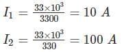
Maximum kVA rating = V.A = VHIH = 3630 × 100 = 363 KVA

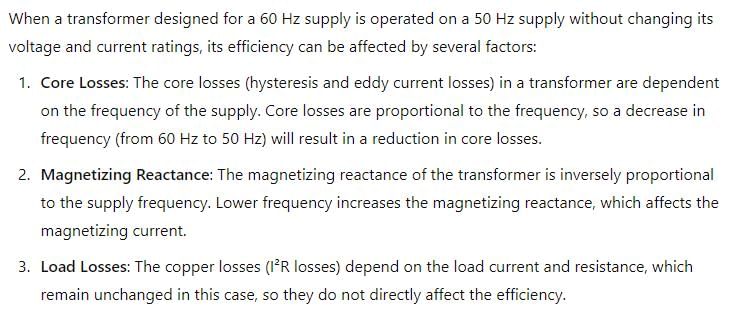
A transformer designed for operation of 60 Hz supply is working on 50 Hz supply system without changing its voltage and current ratings. When compared with full-load efficiency at 60 Hz, the transformer efficiency on full load at 50 Hz will- a)increase by a factor of 1.2
- b)decrease marginally
- c)remain unaltered
- d)increase marginally
Correct answer is option 'D'. Can you explain this answer?
A transformer designed for operation of 60 Hz supply is working on 50 Hz supply system without changing its voltage and current ratings. When compared with full-load efficiency at 60 Hz, the transformer efficiency on full load at 50 Hz will
a)
increase by a factor of 1.2
b)
decrease marginally
c)
remain unaltered
d)
increase marginally
| | Yash Patel answered |
A commutator with a diameter of 50 cm rotates at 1000 rpm. For a brush width of 1.5 cm, the time of commutation is - a)573 μsec
- b)256 msec
- c)625 μsec
- d)448 msec
Correct answer is option 'A'. Can you explain this answer?
A commutator with a diameter of 50 cm rotates at 1000 rpm. For a brush width of 1.5 cm, the time of commutation is
a)
573 μsec
b)
256 msec
c)
625 μsec
d)
448 msec
| | Sanvi Kapoor answered |
Peripheral velocity of commutator is
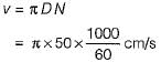
Now, brush width = v x time of commutation
Now, brush width = v x time of commutation
or, time of commutation
Calculate the MMF when the magnetic flux is 5Wb and the reluctance is 3A/Wb.- a)10At
- b)10N
- c)15N
- d)15At
Correct answer is option 'D'. Can you explain this answer?
Calculate the MMF when the magnetic flux is 5Wb and the reluctance is 3A/Wb.
a)
10At
b)
10N
c)
15N
d)
15At
 | Pioneer Academy answered |
We know that:
F = ϕS
Substituting the given values from the question, we get MMF = 15At.
F = ϕS
Substituting the given values from the question, we get MMF = 15At.

Which of the following method would give a lower than actual value of regulation of an alternator?- a)zpf method
- b)mmf method
- c)Emf method
- d)ASA method
Correct answer is option 'B'. Can you explain this answer?
Which of the following method would give a lower than actual value of regulation of an alternator?
a)
zpf method
b)
mmf method
c)
Emf method
d)
ASA method
| | Sanvi Kapoor answered |
Mmf method is called optimistic method because it gives voltage regulation lower than the actual value.
The torque of a reluctance motor can be effectively decreased by- a)decreasing reluctance of the magnetic circuit along the quadrature axis
- b)increasing reluctance of the magnetic circuit along the direct axis
- c)increasing the ratio of quadrature axis reluctance to direct axis reluctance
- d)decreasing the ratio of quadrature axis reluctance to direct axis reluctance
Correct answer is option 'D'. Can you explain this answer?
The torque of a reluctance motor can be effectively decreased by
a)
decreasing reluctance of the magnetic circuit along the quadrature axis
b)
increasing reluctance of the magnetic circuit along the direct axis
c)
increasing the ratio of quadrature axis reluctance to direct axis reluctance
d)
decreasing the ratio of quadrature axis reluctance to direct axis reluctance
| | Ashutosh Majumdar answered |
Torque developed in a reluctance motor is given by
Te ∝ (Rlq - Rld)
If Rlq/Rld is less, it means Rlq < RId and thus, Te is less.
Te ∝ (Rlq - Rld)
If Rlq/Rld is less, it means Rlq < RId and thus, Te is less.
Maximum efficiency of a transformer for a constant load current , occurs at- a)at any p.f
- b)zero p.f leading
- c)zero p.f lagging
- d)unity p.f
Correct answer is option 'D'. Can you explain this answer?
Maximum efficiency of a transformer for a constant load current , occurs at
a)
at any p.f
b)
zero p.f leading
c)
zero p.f lagging
d)
unity p.f
| | Bijoy Mehta answered |
Efficiency = KVA*p.f/(KVA*p.f + Losses); So the efficiency is maximum at unity power factor.
A single phase transformer takes a no load current of 1.3 A when high voltage winding is kept open. If the iron loss component of no load current is 0.5 A, the magnetizing component of no load current will be____ (in A)
Correct answer is between '1.1,1.3'. Can you explain this answer?
A single phase transformer takes a no load current of 1.3 A when high voltage winding is kept open. If the iron loss component of no load current is 0.5 A, the magnetizing component of no load current will be____ (in A)
| | Ameya Gupta answered |
No load current I0 = 1.3 A
Iron loss component IW = 0.5 A
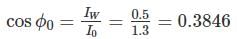
Magnetizing component of no load current
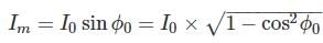
Iron loss component IW = 0.5 A
Magnetizing component of no load current
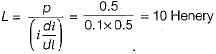
A 110/220 V, 60 Hz, single phase, 1-kVA transformer has leakage reactance of 4%. Calculate its total leakage inductance (in mH) referred to 110 V side.
Correct answer is between '1.25,1.35'. Can you explain this answer?
A 110/220 V, 60 Hz, single phase, 1-kVA transformer has leakage reactance of 4%. Calculate its total leakage inductance (in mH) referred to 110 V side.
| | Jaya Dasgupta answered |
Assuming the 110-V side 1 and the 220-V side to be side 2, N1/N2 = 0.5
Total leakage reactance referred to side 1
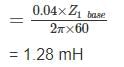
Total leakage reactance referred to side 1
For a core-type power transformers, both primary and secondary windings have circular coil sections, because this section- a)has the strongest mechanical shape.
- b)results in less core material and, therefore, less core loss.
- c)is easier to wind.
- d)require minimum conductor material and, therefore, less I2R loss.
Correct answer is option 'D'. Can you explain this answer?
For a core-type power transformers, both primary and secondary windings have circular coil sections, because this section
a)
has the strongest mechanical shape.
b)
results in less core material and, therefore, less core loss.
c)
is easier to wind.
d)
require minimum conductor material and, therefore, less I2R loss.
| | Lavanya Menon answered |
Primary and secondary windings of a core type transformer have circular coil section to reduce the mean length of each turn so that it require minimum conductor material and thus have less copper loss which will increase the efficiency.
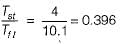
A 3-phase squirrel cage induction motor has maximum torque equal to twice the full-load torque. The per phase rotor resistance and per phase standstill reactance referred to stator are 0.2 Ω and 2 Ω respectively (Stator impedance is neglected). What is the ratio of motor starting toque to its full-load torque, if the motor is started by direct-on-line starter?- a)0.396
- b)0.194
- c)0.198
- d)0.400
Correct answer is option 'A'. Can you explain this answer?
A 3-phase squirrel cage induction motor has maximum torque equal to twice the full-load torque. The per phase rotor resistance and per phase standstill reactance referred to stator are 0.2 Ω and 2 Ω respectively (Stator impedance is neglected). What is the ratio of motor starting toque to its full-load torque, if the motor is started by direct-on-line starter?
a)
0.396
b)
0.194
c)
0.198
d)
0.400
| | Sanskriti Bajaj answered |
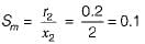
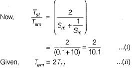
From equations (i) and (ii), we have
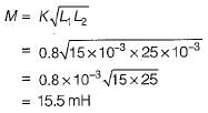
Two inductances of 15 mH and 25 mH are connected in series such that their fluxes oppose each other. They are so placed that the coefficient of coupling is 0.8. The value of mutual inductance between them will be - a)15.5 mH
- b)18 mH
- c)12.6 mH
- d)None of these
Correct answer is option 'A'. Can you explain this answer?
Two inductances of 15 mH and 25 mH are connected in series such that their fluxes oppose each other. They are so placed that the coefficient of coupling is 0.8. The value of mutual inductance between them will be
a)
15.5 mH
b)
18 mH
c)
12.6 mH
d)
None of these
| | Yash Patel answered |
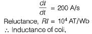
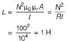
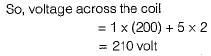
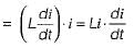
A coil of 100 turns is wound on a torroidal magnetic core having a reluctance of 104 AT/Wb. When the coil current is 5 A and is increasing at the rate of 200 A/s, the voltage across the coil would be (assume coil resistance to be 2 Ω)- a)210 volt
- b)230 volt
- c)115 volt
- d)Zero volt
Correct answer is option 'A'. Can you explain this answer?
A coil of 100 turns is wound on a torroidal magnetic core having a reluctance of 104 AT/Wb. When the coil current is 5 A and is increasing at the rate of 200 A/s, the voltage across the coil would be (assume coil resistance to be 2 Ω)
a)
210 volt
b)
230 volt
c)
115 volt
d)
Zero volt
| | Sanvi Kapoor answered |
For a specified input voltage and frequency, if the equivalent radius of the core of a transformer is reduced by half, the factor by which the number of turns in the primary should change to maintain the same no load current is- a)1/4
- b)1/2
- c)2
- d)4
Correct answer is option 'D'. Can you explain this answer?
For a specified input voltage and frequency, if the equivalent radius of the core of a transformer is reduced by half, the factor by which the number of turns in the primary should change to maintain the same no load current is
a)
1/4
b)
1/2
c)
2
d)
4
| | Niharika Basu answered |
EMT equation of Transformer is given by 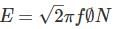
Where f is the flux density, given as ϕ = B × A
Now, the given radius is reduced by half, i.e. r → r/2,
So, the area will be reduced by 1/4 i.e. to maintain no load current constant (in turn emf (EE)) to be constant, number of turns will be 4 times
Where f is the flux density, given as ϕ = B × A
Now, the given radius is reduced by half, i.e. r → r/2,
So, the area will be reduced by 1/4 i.e. to maintain no load current constant (in turn emf (EE)) to be constant, number of turns will be 4 times
A 3-phase, 50 Hz induction motor has a full load speed of 1440 rpm. The number of poles of the motor is- a)4
- b)5
- c)6
- d)None of these
Correct answer is option 'A'. Can you explain this answer?
A 3-phase, 50 Hz induction motor has a full load speed of 1440 rpm. The number of poles of the motor is
a)
4
b)
5
c)
6
d)
None of these
| | Sparsh Nambiar answered |
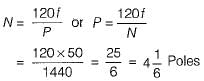
Since the number of poles must be even and a whole number, therefore the number of poles must be 4.
The emf per turn of a single phase 10 kVA, 2200/220 V, 50 Hz transformer is 10 V. The net cross-sectional area of core for a maximum flux density of 1.5 T is- a)300 cm2
- b)200 cm2
- c)100 cm2
- d)25 cm2
Correct answer is option 'A'. Can you explain this answer?
The emf per turn of a single phase 10 kVA, 2200/220 V, 50 Hz transformer is 10 V. The net cross-sectional area of core for a maximum flux density of 1.5 T is
a)
300 cm2
b)
200 cm2
c)
100 cm2
d)
25 cm2
| | Jyoti Basak answered |
Maximum flux,
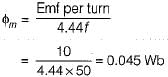
∴ New cross-sectional area of core,
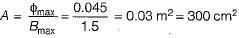
∴ New cross-sectional area of core,
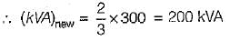
A three - phase alternator is wound with a 60 degree phase spread armature winding and develops 300 kVA. If the armature is reconnected utilizing all the coils for single-phase operation with a phase spread of 180 degree, the new rating of the machine will be- a)300 kVA
- b)200 kVA
- c)100 kVA
- d)250 kVA
Correct answer is option 'B'. Can you explain this answer?
A three - phase alternator is wound with a 60 degree phase spread armature winding and develops 300 kVA. If the armature is reconnected utilizing all the coils for single-phase operation with a phase spread of 180 degree, the new rating of the machine will be
a)
300 kVA
b)
200 kVA
c)
100 kVA
d)
250 kVA
| | Mahesh Singh answered |
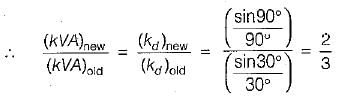
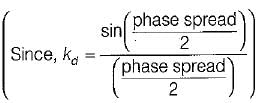
kVA rating, αEf ∝ kd
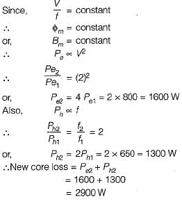
A 220/115 V, 25 Hz single phase transformer has eddy current loss 150W, which is half of the no load loss at rated applied voltage. If the transformer is used with primary 50 Hz 440 V, the total no load loss would be
Correct answer is '900'. Can you explain this answer?
A 220/115 V, 25 Hz single phase transformer has eddy current loss 150W, which is half of the no load loss at rated applied voltage. If the transformer is used with primary 50 Hz 440 V, the total no load loss would be
| | Sanchita Choudhary answered |
Eddy current loss = 150 W
No load loss W0 = 300 W
Now W0 = Wh + We
300 = Wh + 150
Wh = 150 W
Wh ∝ f
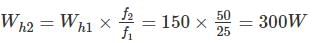
Wh ∝ f2
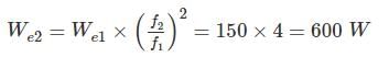
∴ Total no load loss = We2 + Wh2 = 600 + 300 = 900 W
No load loss W0 = 300 W
Now W0 = Wh + We
300 = Wh + 150
Wh = 150 W
Wh ∝ f
Wh ∝ f2
∴ Total no load loss = We2 + Wh2 = 600 + 300 = 900 W
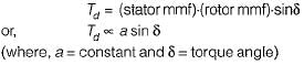
A rotating electromechanical energy conversion device has uniform air-gap. If δ is the space angle between the axis of stator field and rotor field, then the average torque developed is proportional to (a and b are constants)- a)a sin δ + B sin 2δ
- b)a sin δ
- c)a sin 2δ
- d)δ
Correct answer is option 'B'. Can you explain this answer?
A rotating electromechanical energy conversion device has uniform air-gap. If δ is the space angle between the axis of stator field and rotor field, then the average torque developed is proportional to (a and b are constants)
a)
a sin δ + B sin 2δ
b)
a sin δ
c)
a sin 2δ
d)
δ
| | Debanshi Iyer answered |
Average torque developed is
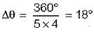
A stepping motor has four concentric coils on its 4-pole stator. It has an unwound variable reluctance motor with 5 teeth. The step angle for this motor is- a)36°
- b)18°
- c)9º
- d)72°
Correct answer is option 'B'. Can you explain this answer?
A stepping motor has four concentric coils on its 4-pole stator. It has an unwound variable reluctance motor with 5 teeth. The step angle for this motor is
a)
36°
b)
18°
c)
9º
d)
72°
| | Rajat Kumar answered |
Step size/angle,

Given,
Nr = Number of rotor teeths = 5
m = Number of phase/stacks = 4
∴
Given,
Nr = Number of rotor teeths = 5
m = Number of phase/stacks = 4
∴
Singly-and doubly-excited magnetic systems are respectively- a)reluctance motor and synchronous motors
- b)dc shunt machines and solenoids
- c)synchronous motors and moving-iron instruments
- d)loud-speakers and tachometers
Correct answer is option 'A'. Can you explain this answer?
Singly-and doubly-excited magnetic systems are respectively
a)
reluctance motor and synchronous motors
b)
dc shunt machines and solenoids
c)
synchronous motors and moving-iron instruments
d)
loud-speakers and tachometers
| | Sanaya Basu answered |
In synchronous-motor, dc excitation is given to rotor for flux generation while it’s stator is connected is 3-φ supply. Therefore, it has doubly- excited system . Reluctance motor is an excitation-less motor ie. it has singly-excited magnetic system.
Consider the following statements related to an universal motor:
1. An universal motor runs on d.c. as well as on a.c.
2. No extra winding is required in a universal motor for ac operation.
3. The direction of rotation of universal motor can be reversed by reversing either the field or armature leads, but not both.
4. Universal motors are designed for operation at low speeds (less than 3500 rpm).
Of these, the correct statements are:- a)2, 3 and 4
- b)1,2 and 4
- c)1 and 2
- d)1 and 3
Correct answer is option 'C'. Can you explain this answer?
Consider the following statements related to an universal motor:
1. An universal motor runs on d.c. as well as on a.c.
2. No extra winding is required in a universal motor for ac operation.
3. The direction of rotation of universal motor can be reversed by reversing either the field or armature leads, but not both.
4. Universal motors are designed for operation at low speeds (less than 3500 rpm).
Of these, the correct statements are:
a)
2, 3 and 4
b)
1,2 and 4
c)
1 and 2
d)
1 and 3
| | Uday Saini answered |
⇒ The compensating winding is required in an universal motor for ac operation to neutralize reactance voltage.
⇒ Universal motors are designed for operation at high speeds (> 3500 rpm).
⇒ Universal motors are designed for operation at high speeds (> 3500 rpm).
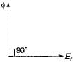
In ac rotating machines, the generated or speed emf - a)Iags φ by 900
- b)Ieads φ by 900
- c)is in phase with the working flux φ
- d)Iags φ by 1800
Correct answer is option 'A'. Can you explain this answer?
In ac rotating machines, the generated or speed emf
a)
Iags φ by 900
b)
Ieads φ by 900
c)
is in phase with the working flux φ
d)
Iags φ by 1800
| | Avik Saha answered |
In ac rotating machines like synchronous generators/motor/induction motors, working flux (φ) leads generated emf by 900. However, in static device like a transformer working flux (φ) lags the applied voltage by 900.
What is the coupling field used between the electrical and mechanical systems in energy conversion devices?- a)Magnetic field or Electric field
- b)Electric field
- c)Magnetic field
- d)None of the mentioned
Correct answer is option 'C'. Can you explain this answer?
What is the coupling field used between the electrical and mechanical systems in energy conversion devices?
a)
Magnetic field or Electric field
b)
Electric field
c)
Magnetic field
d)
None of the mentioned
| | Pooja Patel answered |
Either electric field or magnetic field can be used, however most commonly we use magnetic field because of its greater energy storage capacity.
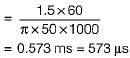
Three transformers having identical dimensions but with core of iron, aluminium and wood are wound with same number of turns and have same supply.Then choose the order for hysteresis losses.- a)wood > aluminium > iron
- b)aluminium > iron > wood
- c)iron > wood > aluminium
- d)iron > aluminium > wood
Correct answer is option 'D'. Can you explain this answer?
Three transformers having identical dimensions but with core of iron, aluminium and wood are wound with same number of turns and have same supply.Then choose the order for hysteresis losses.
a)
wood > aluminium > iron
b)
aluminium > iron > wood
c)
iron > wood > aluminium
d)
iron > aluminium > wood
| | Aarya Basu answered |
Hysteresis losses occur maximum in the ferromagnetic material.
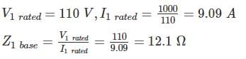
A 50 KVA, 11000/400 V Δ-Y distribution transformer has a resistance of 1% and reactance of 7% per unit. What is the transformer phase impedance referred to the high-voltage side?- a)78.6 + j 608.2
- b)72.6 + j 508.2
- c)62.6 + j 908.2
- d)65.6 + j 786.2
Correct answer is option 'B'. Can you explain this answer?
A 50 KVA, 11000/400 V Δ-Y distribution transformer has a resistance of 1% and reactance of 7% per unit. What is the transformer phase impedance referred to the high-voltage side?
a)
78.6 + j 608.2
b)
72.6 + j 508.2
c)
62.6 + j 908.2
d)
65.6 + j 786.2
| | Sanskriti Kaur answered |
∴ Its base impedance
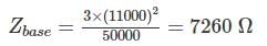
The PU impedance of the transformer is
Zeq = [0.01 + j 0.07] PU
So the high-side impedance in ohm is
Zeq = Zeq pu × Zbase
= (0.01 + j0.07) × 7260 Ω
= 72.6 + j 508.2
The PU impedance of the transformer is
Zeq = [0.01 + j 0.07] PU
So the high-side impedance in ohm is
Zeq = Zeq pu × Zbase
= (0.01 + j0.07) × 7260 Ω
= 72.6 + j 508.2
While comparing potential transformer to an auto transformer, a potential transformer transfers power ________- a)inductively
- b)conductively
- c)both conductively as well as inductively
- d)electromagnetic induction
Correct answer is option 'A'. Can you explain this answer?
While comparing potential transformer to an auto transformer, a potential transformer transfers power ________
a)
inductively
b)
conductively
c)
both conductively as well as inductively
d)
electromagnetic induction
 | EduRev GATE answered |
A potential transformer is a device that transfers electrical power through inductive coupling. This means it uses electromagnetic fields to transfer energy from one circuit to another without direct electrical connection.
- A potential transformer is primarily used for measurement and protection in power systems.
- It provides isolation between the high-voltage circuit and the measuring instruments.
- Power transfer occurs inductively rather than conductively.
In contrast, an auto transformer can transfer power both conductively and inductively, as it has common windings between the input and output.
In various types of split-phase, 1-phase induction motors, the starting torques produced are in the following descending order.- a)Capacitor-split, resistance-split, shaded pole
- b)Resistor-split, capacitor-split, shaded pole
- c)Shaded pole, resistor-split, capacitor split
- d)Capacitor-split, resistor-split, shaded pole
Correct answer is option 'A'. Can you explain this answer?
In various types of split-phase, 1-phase induction motors, the starting torques produced are in the following descending order.
a)
Capacitor-split, resistance-split, shaded pole
b)
Resistor-split, capacitor-split, shaded pole
c)
Shaded pole, resistor-split, capacitor split
d)
Capacitor-split, resistor-split, shaded pole
| | Anirban Chawla answered |
Shaded pole motor has smallest starting torque and spe e d (1 - 2 rpm) .Tst of capacitor-split phase IM > Tst of resistance-split phase IM.
LAP winding is employed in a dc machine of- a)high current and low voltage rating
- b)low current and high voltage rating
- c)high current and high voltage rating
- d)low current and low voltage rating
Correct answer is option 'A'. Can you explain this answer?
LAP winding is employed in a dc machine of
a)
high current and low voltage rating
b)
low current and high voltage rating
c)
high current and high voltage rating
d)
low current and low voltage rating
| | Malavika Nair answered |
For LAP winding, number of parallel path = number of poles.
Thus, resistance is less compared to wave winding. Hence, current rating is more and voltage rating is less compared to wave winding.
Thus, resistance is less compared to wave winding. Hence, current rating is more and voltage rating is less compared to wave winding.
A 6-pole, 50 Hz, 3-phase induction motor has a stator bore diameter of 1.2 meters, its stator is cut and laid out flat, so that rotating mmf wave now becomes a travelling mmf wave. What is the linear velocity of the travelling mmf wave in meters per second ?- a)56.6
- b)62.8
- c)36.4
- d)None of these
Correct answer is option 'B'. Can you explain this answer?
A 6-pole, 50 Hz, 3-phase induction motor has a stator bore diameter of 1.2 meters, its stator is cut and laid out flat, so that rotating mmf wave now becomes a travelling mmf wave. What is the linear velocity of the travelling mmf wave in meters per second ?
a)
56.6
b)
62.8
c)
36.4
d)
None of these
| | Nitin Chawla answered |
To determine the linear velocity of the traveling mmf wave in a 6-pole, 50 Hz, 3-phase induction motor, we need to consider the relationship between the number of poles, frequency, and the linear velocity of the wave.
Given data:
Number of poles (p) = 6
Frequency (f) = 50 Hz
Stator bore diameter (D) = 1.2 meters
First, we need to calculate the synchronous speed (Ns) of the motor using the formula:
Ns = 120f/p
where Ns is the synchronous speed in RPM, f is the frequency in Hz, and p is the number of poles.
Plugging in the given values, we have:
Ns = 120 * 50 / 6
Ns = 1000 RPM
Next, we can calculate the linear velocity of the rotating mmf wave (Vr) using the formula:
Vr = πDNs / 60
where Vr is the linear velocity in meters per second, D is the stator bore diameter in meters, Ns is the synchronous speed in RPM, and π is a constant (approximately 3.14).
Plugging in the values, we get:
Vr = 3.14 * 1.2 * 1000 / 60
Vr ≈ 62.8 m/s
Since the stator is cut and laid out flat, the rotating mmf wave becomes a traveling mmf wave. The linear velocity of the traveling mmf wave (Vt) will be the same as the linear velocity of the rotating mmf wave (Vr).
Therefore, the linear velocity of the traveling mmf wave in meters per second is approximately 62.8 m/s.
Hence, the correct answer is option B) 62.8.
A 3-phase bank of three single phase transformer are fed from 3 phase 33 kV (L-L). It supplies a load of 5000 kVA at 11 kV (L-L). Both supply and load three wire. Calculate the voltage rating of single phase transformer for start-delta connection.- a)33/11 kV
- b)33/635 kV
- c)19.05/11 kV
- d)19.05/6.35 kV
Correct answer is option 'C'. Can you explain this answer?
A 3-phase bank of three single phase transformer are fed from 3 phase 33 kV (L-L). It supplies a load of 5000 kVA at 11 kV (L-L). Both supply and load three wire. Calculate the voltage rating of single phase transformer for start-delta connection.
a)
33/11 kV
b)
33/635 kV
c)
19.05/11 kV
d)
19.05/6.35 kV
| | Aman Jain answered |
For star-delta connection
Primary side phase voltage
Secondary side phase voltage = 11
∴ Transformer voltage rating 19.05/11 kV
Primary side phase voltage
Secondary side phase voltage = 11
∴ Transformer voltage rating 19.05/11 kV
A 24 kW, 250 V, 1600 rpm separately-excited d.c. generator has armature circuit resistance of 0.1Ω. The machine is first run at rated speed and the field winding current is adjusted to give an open circuit voltage of 260 V. Now, when the generator is loaded to deliver its rated current, the speed of the driving motor is found to be 1500 r.p.m. Assuming flux to remain constant, the terminal voltage of the generator under these conditions is- a)250 volt
- b)226 volt
- c)238 volt
- d)234 volt
Correct answer is option 'D'. Can you explain this answer?
A 24 kW, 250 V, 1600 rpm separately-excited d.c. generator has armature circuit resistance of 0.1Ω. The machine is first run at rated speed and the field winding current is adjusted to give an open circuit voltage of 260 V. Now, when the generator is loaded to deliver its rated current, the speed of the driving motor is found to be 1500 r.p.m. Assuming flux to remain constant, the terminal voltage of the generator under these conditions is
a)
250 volt
b)
226 volt
c)
238 volt
d)
234 volt
| | Kajal Mukherjee answered |
We know that,
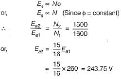
Now, rated armature current is
So, the terminal voltage is
Now, rated armature current is
So, the terminal voltage is
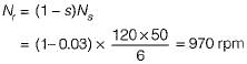
A 125 W, 4-pole, 110 V, 50 Hz single phase induction motor delivers rated output at a slip of 6%. The total copper loss at full load is 25 Watts. Rotational loss may be assumed to be 25 Watts. Neglecting stator copper loss, the full-load efficiency of the motor would be:- a)71.43%
- b)88.62%
- c)75%
- d)90.08%
Correct answer is option 'A'. Can you explain this answer?
A 125 W, 4-pole, 110 V, 50 Hz single phase induction motor delivers rated output at a slip of 6%. The total copper loss at full load is 25 Watts. Rotational loss may be assumed to be 25 Watts. Neglecting stator copper loss, the full-load efficiency of the motor would be:
a)
71.43%
b)
88.62%
c)
75%
d)
90.08%
| | Lakshmi Desai answered |
Solution:
Given data:
P_out = 125 W
N = 4 poles
V = 110 V
f = 50 Hz
Slip (s) = 6%
Total copper loss = 25 W
Rotational loss = 25 W
Calculations:
1. Synchronous Speed (N_s)
N_s = (120 * f) / N
N_s = (120 * 50) / 4
N_s = 1500 rpm
2. Rotor Speed (N_r)
N_r = (1 - s) * N_s
N_r = (1 - 0.06) * 1500
N_r = 1410 rpm
3. Number of poles (P)
P = 2 * N / 60
P = 2 * 4 / 60
P = 0.1333
4. Rotor copper loss (P_c)
P_c = s * P_out
P_c = 0.06 * 125
P_c = 7.5 W
5. Power developed by rotor (P_r)
P_r = P_out + P_c + Rotational loss
P_r = 125 + 7.5 + 25
P_r = 157.5 W
6. Total input power (P_in)
P_in = P_r + Total copper loss
P_in = 157.5 + 25
P_in = 182.5 W
7. Efficiency (η)
η = P_out / P_in * 100
η = 125 / 182.5 * 100
η = 68.49%
Since the question neglects stator copper loss, the efficiency can be improved by reducing the copper loss. Therefore, the full-load efficiency of the motor would be higher than 68.49%.
8. Full-load efficiency (η_f)
η_f = η + (Stator copper loss / P_in * 100)
η_f = 68.49 + (0 / 182.5 * 100)
η_f = 68.49%
Therefore, the full-load efficiency of the motor neglecting stator copper loss is 71.43% (approx.) which is closest to option A.
The power factor of a delta-connected 3-phase, 50 kW, IM is 0.4 when delivering 35% of its rated load. If the stator is reconnected in star, then its- a)pf is worsened, stator current increases
- b)pf is improved, stator current increases
- c)pf remains unchanged, stator current decreases
- d)pf is improved, stator current decreases.
Correct answer is option 'D'. Can you explain this answer?
The power factor of a delta-connected 3-phase, 50 kW, IM is 0.4 when delivering 35% of its rated load. If the stator is reconnected in star, then its
a)
pf is worsened, stator current increases
b)
pf is improved, stator current increases
c)
pf remains unchanged, stator current decreases
d)
pf is improved, stator current decreases.
| | Anoushka Kumar answered |
We know that,

∴
Thus, stator current will decrease.

∴
Thus, stator current will decrease.
Match List-I (Type of motors) with List-ll (Characteristics) and select the correct answer using the codes given below the lists:
List-I
A. Shaded Pole motor
B. Hysteresis motor
C. PMDC motor
D. Capacitor start motor
List-ll
1. Least noise
2. Highest starting torque
3. Lowest speed
4. Used in cassette tape recorder
Codes:
A B C D
(a) 3 4 2 1
(b) 1 4 2 3
(c) 3 1 4 2
(d) 1 2 3 4- a)(a)
- b)(b)
- c)(c)
- d)(d)
Correct answer is option 'C'. Can you explain this answer?
Match List-I (Type of motors) with List-ll (Characteristics) and select the correct answer using the codes given below the lists:
List-I
A. Shaded Pole motor
B. Hysteresis motor
C. PMDC motor
D. Capacitor start motor
List-ll
1. Least noise
2. Highest starting torque
3. Lowest speed
4. Used in cassette tape recorder
Codes:
A B C D
(a) 3 4 2 1
(b) 1 4 2 3
(c) 3 1 4 2
(d) 1 2 3 4
List-I
A. Shaded Pole motor
B. Hysteresis motor
C. PMDC motor
D. Capacitor start motor
List-ll
1. Least noise
2. Highest starting torque
3. Lowest speed
4. Used in cassette tape recorder
Codes:
A B C D
(a) 3 4 2 1
(b) 1 4 2 3
(c) 3 1 4 2
(d) 1 2 3 4
a)
(a)
b)
(b)
c)
(c)
d)
(d)
| | Aman Jain answered |
Capacitor start motor has highest starting toque. Hysteresis motor gives noise less operation.
Which of the following is not true relating to an ideal transformer?- a)The iron loss in an ideal transformer is zero
- b)The winding resistance has a zero value
- c)The leakage reactance has a non-zero value
- d)The magnetizing current is zero
Correct answer is option 'C'. Can you explain this answer?
Which of the following is not true relating to an ideal transformer?
a)
The iron loss in an ideal transformer is zero
b)
The winding resistance has a zero value
c)
The leakage reactance has a non-zero value
d)
The magnetizing current is zero
| | Kajal Yadav answered |
In an ideal transformer there is no-loss (either in winding or core). The leakage reactance is also zero (as no-voltage drop).
Magnetizing current is zero due to infinite permeability of core.
Magnetizing current is zero due to infinite permeability of core.
An electro-mechanical energy conversion device is one which converts _______- a)Electrical energy to mechanical energy only
- b)Mechanical energy to electrical energy only
- c)Electrical to mechanical and mechanical to electrical
- d)None of the mentioned
Correct answer is option 'C'. Can you explain this answer?
An electro-mechanical energy conversion device is one which converts _______
a)
Electrical energy to mechanical energy only
b)
Mechanical energy to electrical energy only
c)
Electrical to mechanical and mechanical to electrical
d)
None of the mentioned
| | Zoya Sharma answered |
The operating principles of electrical to mechanical and mechanical to electrical conversion devices are similar, hence, the common name electro-mechanical device. However, their structural details differ depending on their function.
A 10 kVA, 400 V/ 200 V, 1 -phase transformer with a percentage resistance of 3% and percentage reactance of 6% is supplying a current of 50 A to a resistive load. The value of the load voltage is- a)390 V
- b)194 V
- c)196 V
- d)192 V
Correct answer is option 'B'. Can you explain this answer?
A 10 kVA, 400 V/ 200 V, 1 -phase transformer with a percentage resistance of 3% and percentage reactance of 6% is supplying a current of 50 A to a resistive load. The value of the load voltage is
a)
390 V
b)
194 V
c)
196 V
d)
192 V
| | Manoj Chaudhary answered |
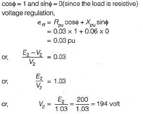
Hence, load voltage = 194 volt
A 1 kVA, 200/100 V, 50 Hz, single phase transformer gave the following results on 50 Hz:
OC (LV side): 100 V, 20 watts
SC (HV side): 5 A, 25 watts
It is assumed that no load loss components are equally divided. The above tests were then conducted on the same transformer at 40 Hz. Test results are
OC (HV): 160 V, W1 watts
SC (LV): 10 A, W2 watts
Neglecting skin effect, W1 and W2 will be- a)16 W, 25 W
- b)25 W, 31.25 W
- c)20 W, 20 W
- d)14.4 W, 25 W
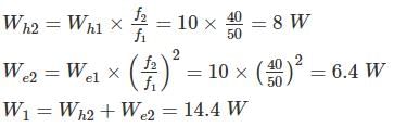
Correct answer is option 'D'. Can you explain this answer?
A 1 kVA, 200/100 V, 50 Hz, single phase transformer gave the following results on 50 Hz:
OC (LV side): 100 V, 20 watts
SC (HV side): 5 A, 25 watts
It is assumed that no load loss components are equally divided. The above tests were then conducted on the same transformer at 40 Hz. Test results are
OC (HV): 160 V, W1 watts
SC (LV): 10 A, W2 watts
Neglecting skin effect, W1 and W2 will be
OC (LV side): 100 V, 20 watts
SC (HV side): 5 A, 25 watts
It is assumed that no load loss components are equally divided. The above tests were then conducted on the same transformer at 40 Hz. Test results are
OC (HV): 160 V, W1 watts
SC (LV): 10 A, W2 watts
Neglecting skin effect, W1 and W2 will be
a)
16 W, 25 W
b)
25 W, 31.25 W
c)
20 W, 20 W
d)
14.4 W, 25 W
| | Sanskriti Bajaj answered |
Given that no load losses components are equally divided
Wh = We = 10W
Initially test is conducted on LV side
Now V/f ratio is 100/50 = 2
In HV side, applied voltage is 160 V, this voltage on LV side is equal to 80 V.
Now V/f ratio is constant, Wh ∝ f, We ∝ f2
In SC test
I(HV side) = 5 A
I(LV side) = 10 A
As the SC tests were conducted at rated current on both sides, the copper losses are same.
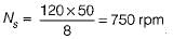
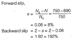
A properly shunted centre-zero galvanometer is connected in the rotor circuit of a 6-pole, 50 Hz would-rotor induction motor. If the galvanometer makes 90 complete oscillations in one minute, the speed of rotor would be- a)1000 rpm
- b)740 rpm
- c)880 rpm
- d)970 rpm
Correct answer is option 'D'. Can you explain this answer?
A properly shunted centre-zero galvanometer is connected in the rotor circuit of a 6-pole, 50 Hz would-rotor induction motor. If the galvanometer makes 90 complete oscillations in one minute, the speed of rotor would be
a)
1000 rpm
b)
740 rpm
c)
880 rpm
d)
970 rpm
| | Naveen Mukherjee answered |
Rotor frequency,
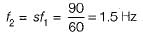
∴ Slip,
So, rotor speed,
∴ Slip,
So, rotor speed,
In a split phase motor- a)the starting winding is connected through a centrifugal switch
- b)the running winding is connected through a centrifugal switch
- c)both starting and running windings are connected through a centrifugal switch
- d)centrifugal switch is used to control supply voltage
Correct answer is option 'A'. Can you explain this answer?
In a split phase motor
a)
the starting winding is connected through a centrifugal switch
b)
the running winding is connected through a centrifugal switch
c)
both starting and running windings are connected through a centrifugal switch
d)
centrifugal switch is used to control supply voltage
| | Hridoy Chakraborty answered |
Split Phase Motor and Centrifugal Switch
Split phase motors are single-phase induction motors that have two windings - a starting winding and a running winding. These windings are placed at right angles to each other and are connected to the main winding of the motor. The starting winding has more turns, and it is also smaller in size than the running winding.
Centrifugal switch is an electro-mechanical device that is used to open or close an electrical circuit based on the rotational speed of a shaft or rotor. In split phase motors, a centrifugal switch is used to disconnect the starting winding from the power supply once the motor has reached a certain speed.
Answer Explanation
The correct option is 'A' - the starting winding is connected through a centrifugal switch.
When a split phase motor is started, both the starting and running windings are energized. The starting winding produces a magnetic field that is shifted by 90 degrees from the magnetic field produced by the running winding. This results in a rotating magnetic field that causes the rotor to start rotating.
Once the motor has reached around 70-80% of its rated speed, the centrifugal switch opens and disconnects the starting winding from the power supply. This is necessary because if the starting winding remains energized, it will produce a magnetic field that will interfere with the magnetic field produced by the running winding. This will cause the motor to overheat and eventually fail.
Therefore, the centrifugal switch is used to prevent this from happening by disconnecting the starting winding once the motor is up to speed. The running winding then takes over and continues to produce the rotating magnetic field that drives the motor.
In summary, the correct option is 'A' because the centrifugal switch is used to connect and disconnect the starting winding from the power supply in a split phase motor.
For eliminating 3rd harmonic from the phase emf generated in an alternator, the coil span in terms of full-pitch would be- a)5/4
- b)4/3
- c)5/3
- d)2/3
Correct answer is option 'D'. Can you explain this answer?
For eliminating 3rd harmonic from the phase emf generated in an alternator, the coil span in terms of full-pitch would be
a)
5/4
b)
4/3
c)
5/3
d)
2/3
| | Aniket Shah answered |
For eliminating nth harmonic,
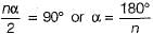
∴ Coil span of short-pitched winding
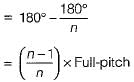
For eliminating 3rd harmonic, coil-span
= 2/3 x Full-pitch
∴ Coil span of short-pitched winding
For eliminating 3rd harmonic, coil-span
= 2/3 x Full-pitch
If ϕm is the maximum value of flux due to any one phase, the resultant flux in 3-phase and 2-phase ac machines would be given by- a)2 ϕm and 1.5 ϕm; both rotating
- b)1.5 ϕm, rotating and ϕm, standstill
- c)1.5 ϕm, and ϕm; both standstill
- d)1.5 ϕm, and ϕm; both rotating
Correct answer is option 'D'. Can you explain this answer?
If ϕm is the maximum value of flux due to any one phase, the resultant flux in 3-phase and 2-phase ac machines would be given by
a)
2 ϕm and 1.5 ϕm; both rotating
b)
1.5 ϕm, rotating and ϕm, standstill
c)
1.5 ϕm, and ϕm; both standstill
d)
1.5 ϕm, and ϕm; both rotating
| | Nayanika Kaur answered |
The correct answer is option 'D': 1.5 m and m; both rotating.
Explanation:
In 3-phase and 2-phase ac machines, the resultant flux is determined by the sum of the individual fluxes produced by each phase. Let's analyze the given options to understand which one is correct.
a) 2 m and 1.5 m; both rotating
This option suggests that the maximum value of flux due to any one phase is m. In a 3-phase system, the maximum value of flux due to any one phase is m. Therefore, the total resultant flux would be 3m for a rotating 3-phase machine. However, for a 2-phase machine, there are only two phases. So, the total resultant flux would be 2m. Hence, this option is incorrect.
b) 1.5 m, rotating and m, standstill
This option suggests that the maximum value of flux due to any one phase is m. In a 3-phase system, the maximum value of flux due to any one phase is m. Therefore, the total resultant flux would be 3m for a rotating 3-phase machine. However, for a 2-phase machine, there are only two phases. So, the total resultant flux would be 2m. Hence, this option is incorrect.
c) 1.5 m and m; both standstill
This option suggests that the maximum value of flux due to any one phase is m. In a 3-phase system, the maximum value of flux due to any one phase is m. Therefore, the total resultant flux would be 3m for a rotating 3-phase machine. However, for a standstill machine, there is no rotation, and the flux remains constant. Hence, this option is incorrect.
d) 1.5 m and m; both rotating
This option suggests that the maximum value of flux due to any one phase is m. In a 3-phase system, the maximum value of flux due to any one phase is m. Therefore, the total resultant flux would be 3m for a rotating 3-phase machine. Similarly, for a 2-phase machine, there are only two phases, and the total resultant flux would be 2m. Since both machines are rotating, this option is correct.
In summary, the resultant flux in 3-phase and 2-phase ac machines is given by 1.5 m and m, respectively, when both are rotating.
The statements which support the points that auto transformers are disadvantageous as compared to 2-winding transformer
I. Weight of conductor reduces
II. Direct electrical contacts
III. Leakage reactance reduces
IV. Lower short-circuit current- a)I,III
- b)II,III
- c)II,IV
- d)I,II,IV
Correct answer is option 'C'. Can you explain this answer?
The statements which support the points that auto transformers are disadvantageous as compared to 2-winding transformer
I. Weight of conductor reduces
II. Direct electrical contacts
III. Leakage reactance reduces
IV. Lower short-circuit current
I. Weight of conductor reduces
II. Direct electrical contacts
III. Leakage reactance reduces
IV. Lower short-circuit current
a)
I,III
b)
II,III
c)
II,IV
d)
I,II,IV
| | Arshiya Basu answered |
Direct electrical contacts is a disadvantage to the auto transformer.
Short circuit current of the auto transformer is higher than the corresponding 2-winding transformer.
Short circuit current of the auto transformer is higher than the corresponding 2-winding transformer.
If a transformer is at no load , then it will act like- a)a resistor at p.f =0
- b)an inductive reactor at 0.2 lagging
- c)a capacitive reactor at0.2 leading
- d)an inductive reactor at 0.8 lagging
Correct answer is option 'B'. Can you explain this answer?
If a transformer is at no load , then it will act like
a)
a resistor at p.f =0
b)
an inductive reactor at 0.2 lagging
c)
a capacitive reactor at0.2 leading
d)
an inductive reactor at 0.8 lagging
| | Manoj Chaudhary answered |
Transformer is nothing but the arranged windings which are magnetically coupled. The windings will inductive predominantly with very low resistance.
In a hysteresis motor, the rotor must have- a)retentivity
- b)resistivity
- c)susceptibility
- d)none of the above
Correct answer is option 'A'. Can you explain this answer?
In a hysteresis motor, the rotor must have
a)
retentivity
b)
resistivity
c)
susceptibility
d)
none of the above
| | Ritika Sarkar answered |
Hysteresis motor is a type of synchronous motor that operates by the principle of hysteresis loss. The rotor of this motor is made up of a ferromagnetic material with high retentivity, which means it can retain a large amount of magnetism even in the absence of an external magnetic field.
Explanation:
• Retentivity is a characteristic of a magnetic material that determines the amount of magnetism it can retain. In hysteresis motor, the rotor must have high retentivity so that it can maintain a strong magnetic field even in the absence of an external magnetic field.
• The stator of the hysteresis motor produces a rotating magnetic field, which induces a magnetic field in the rotor. Due to the high retentivity of the rotor material, the induced magnetic field in the rotor lags behind the rotating magnetic field of the stator.
• This lagging causes the rotor to rotate in the direction of the rotating magnetic field of the stator. The hysteresis motor does not require any external excitation, and it operates on the principle of hysteresis loss.
• The rotor of the hysteresis motor also requires low resistivity to reduce the power loss due to eddy currents. However, susceptibility is not a relevant characteristic for the hysteresis motor rotor.
Conclusion:
Therefore, from the above explanation, we can conclude that in a hysteresis motor, the rotor must have high retentivity to maintain a strong magnetic field even in the absence of an external magnetic field.
Chapter doubts & questions for Electrical Machines - Topicwise Question Bank for Electrical Engineering 2026 is part of Electrical Engineering (EE) exam preparation. The chapters have been prepared according to the Electrical Engineering (EE) exam syllabus. The Chapter doubts & questions, notes, tests & MCQs are made for Electrical Engineering (EE) 2026 Exam. Find important definitions, questions, notes, meanings, examples, exercises, MCQs and online tests here.
Chapter doubts & questions of Electrical Machines - Topicwise Question Bank for Electrical Engineering in English & Hindi are available as part of Electrical Engineering (EE) exam. Download more important topics, notes, lectures and mock test series for Electrical Engineering (EE) Exam by signing up for free.