


All Exams > Mechanical Engineering > Solid Mechanics > All Questions
All questions of Shear Force & Bending Moment Diagrams (SFD & BMD) for Mechanical Engineering Exam
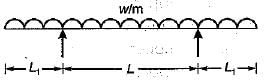
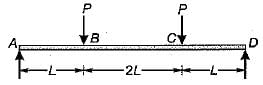
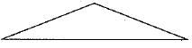
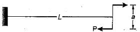
For the beam shown ih the given figure, the maximum positive bending moment is equal to the maximum negative bending moment. The value of L1 is
- a)L/√2
- b)L/√3
- c)L/2
- d)L/2√2
Correct answer is option 'D'. Can you explain this answer?
For the beam shown ih the given figure, the maximum positive bending moment is equal to the maximum negative bending moment. The value of L1 is
a)
L/√2
b)
L/√3
c)
L/2
d)
L/2√2
 | Milan Ghosh answered |
The BM can be found from the area of SFD.
The shear force diagram is
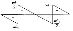
Maximum negative, bending moment,

Maximum positive, bending moment,
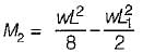
For M1 = M2

The shear force diagram is
Maximum negative, bending moment,
Maximum positive, bending moment,
For M1 = M2

If a beam is subjected to a constant bending moment along its length then the shear force will- a)also have a constant value every where along its length
- b)be zero at all sections along the beam
- c)be maximum at the centre and zero at the ends
- d)be maximum at the ends and zero at the centre
Correct answer is option 'B'. Can you explain this answer?
If a beam is subjected to a constant bending moment along its length then the shear force will
a)
also have a constant value every where along its length
b)
be zero at all sections along the beam
c)
be maximum at the centre and zero at the ends
d)
be maximum at the ends and zero at the centre
| | Milan Ghosh answered |
The relation between shear force (V) and bending moment (M) is:
dM/dx = V
it means the slope of a bending moment diagram will represent the magnitude of shear force at that section.
Since the bending moment is constant along the length, therefore its derivative i.e. shear force is equal to zero at all sections along the beam.
There is no shear force between the loads and the bending moment is constant for that section along the length and vice-versa.
There is no shear force between the loads and the bending moment is constant for that section along the length and vice-versa.
Additional Information
The relation between shear force (V) and loading rate (w) is:
dV/dx = w
it means a positive slope of the shear force diagram represents an upward loading rate.
The relation between loading rate and shear force can be written as:

Bending moment in the a beam is not a function of- a)Position of the load
- b)Cross section of the beam
- c)Type of beam
- d)Span of the beam
Correct answer is option 'B'. Can you explain this answer?
Bending moment in the a beam is not a function of
a)
Position of the load
b)
Cross section of the beam
c)
Type of beam
d)
Span of the beam
| | Aniket Pillai answered |
Bending Moment in a Beam
Bending moment in a beam is the internal moment that causes the beam to bend or deflect when subjected to an external load. It is an important parameter in the design of beams as it helps in determining the strength and stability of the beam.
Factors Affecting Bending Moment
There are several factors that affect the bending moment in a beam. These include:
1. Position of the Load
The position of the load on the beam has a significant effect on the bending moment. The bending moment is maximum at the point where the load is applied and decreases as we move away from the load.
2. Type of Beam
The type of beam used also affects the bending moment. Different types of beams such as simply supported, cantilever, and continuous beams have different bending moments.
3. Span of the Beam
The span of the beam is the distance between the supports. The bending moment increases with an increase in the span of the beam.
4. Cross Section of the Beam
The cross section of the beam also affects the bending moment. Beams with a larger cross-sectional area have a higher bending moment capacity than those with a smaller cross-sectional area.
Answer
The correct answer is option B, i.e., cross section of the beam. The cross section of the beam does not affect the bending moment. However, it affects the moment of inertia, which is used to calculate the bending stress in the beam. The bending moment is dependent on the other factors mentioned above.
If the magnitude of shear force is constant, then the magnitude of the slope of bending moment curve is- a)zero
- b)increasing
- c)constant
- d)decreasing
Correct answer is option 'C'. Can you explain this answer?
If the magnitude of shear force is constant, then the magnitude of the slope of bending moment curve is
a)
zero
b)
increasing
c)
constant
d)
decreasing
 | Garima Kulkarni answered |
Explanation:
The following point should always be kept in mind while drawing SFD and BMD:
1. The rate of change of the shear force at any point on the axis of the beam is equal to the negative of the intensity of the distributed load at that same point.
i.e. w=−dV/dx
Here, negative sign represents that the loading is acting downward.
2. The rate of change of the bending moment at any point on the axis of a beam is equal to the shear force at that same point.
i.e. V=dM/dx
Calculation: -
From (2),
We have,
dM/dx=V=constant
Thus,
The magnitude of slope of moment diagram is also constant.
The point of contraflexure in a beam is at the location where the- a)deflection changes sign
- b)beam develops crack
- c)radius of curvature changes sign
- d)bending moment is zero
Correct answer is option 'D'. Can you explain this answer?
The point of contraflexure in a beam is at the location where the
a)
deflection changes sign
b)
beam develops crack
c)
radius of curvature changes sign
d)
bending moment is zero
 | Atharva Rane answered |
Explanation:
The point of contraflexure in a beam is the location where the shear force is maximum. Contraflexure refers to the change in sign of the bending moment along the length of the beam. It occurs when the beam is subjected to a combination of loading conditions that cause the bending moment to change direction.
When a beam is loaded, it experiences both bending moment and shear force. The bending moment causes the beam to bend and the shear force causes the beam to shear. The distribution of bending moment and shear force along the length of the beam is influenced by the type and magnitude of the applied loads.
Shear Force and Bending Moment:
Shear force is the internal force that tends to shear or cut a beam along its cross-section. It is responsible for the transverse loads that act on a beam. Bending moment, on the other hand, is the internal moment that causes a beam to bend. It is responsible for the sagging or hogging of the beam.
Contraflexure:
Contraflexure occurs when the bending moment changes sign along the length of the beam. This means that the beam changes from sagging to hogging or vice versa. The point of contraflexure is the location where this sign change occurs.
Significance of Contraflexure:
The point of contraflexure is an important location in the beam as it indicates the transition from one bending moment condition to another. It is often associated with the maximum shear force in the beam. At the point of contraflexure, the shear force is at its maximum value.
The maximum shear force occurs at the point of contraflexure because it is the location where the bending moment changes sign. This change in sign results in a rapid change in the internal forces and stresses within the beam, leading to the maximum shear force.
Conclusion:
In summary, the point of contraflexure in a beam is the location where the shear force is maximum. It occurs when the bending moment changes sign along the length of the beam. The maximum shear force at the point of contraflexure is a result of the rapid change in internal forces and stresses within the beam.
In the case of l-section, the web resists mainly- a)Axial force
- b)Shear force
- c)Bending moment
- d)Both shear force and bending moment
Correct answer is option 'B'. Can you explain this answer?
In the case of l-section, the web resists mainly
a)
Axial force
b)
Shear force
c)
Bending moment
d)
Both shear force and bending moment
| | Bhaskar Mukherjee answered |
In the case of (-section, nearly 80-90% shear force, is resisted by web and only 10-20% is resisted by flanges, whereas in bending. 80-90% moment is resisted by flanges and only 10-20% by the web.

The point where the bending moment is zero after changing its sign is known as- a)point of failure
- b)point of maximum shear force
- c)point of contraflexure
- d)point of maximum deflection
Correct answer is option 'C'. Can you explain this answer?
The point where the bending moment is zero after changing its sign is known as
a)
point of failure
b)
point of maximum shear force
c)
point of contraflexure
d)
point of maximum deflection
| | Sanya Agarwal answered |
Points of zero bending moment
- The points of contra flexure are points of zero bending moment, i.e. where the beam changes its curvature from hogging to sagging.
- In a bending beam, a point of contra flexure is a location where the bending moment is zero (changes its sign).
- In a bending moment diagram, it is the point at which the bending moment curve intersects with the zero lines.
Point of inflexion:
- Point of inflexion is the point where the elastic deflection curve changes its curvature not bending moment diagram.
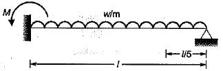
A cantilever carrying uniformly distributed load W over its full length is propped at its free end such that it is at the level of the fixed end. The bending moment will be zero at its free end and also at- a)mid point of the cantilever
- b)fixed point of the cantilever
- c)1/4th length from free end
- d)3/4th length from free end
Correct answer is option 'D'. Can you explain this answer?
A cantilever carrying uniformly distributed load W over its full length is propped at its free end such that it is at the level of the fixed end. The bending moment will be zero at its free end and also at
a)
mid point of the cantilever
b)
fixed point of the cantilever
c)
1/4th length from free end
d)
3/4th length from free end
| | Anirudh Kulkarni answered |
Explanation:
When a cantilever is propped at its free end, the reaction force at the prop is equal and opposite to the load W. This means that the cantilever is in equilibrium and the bending moment at any point along the length of the cantilever must be zero.
However, the distribution of the bending moment is not uniform along the length of the cantilever. It is maximum at the fixed end and decreases towards the free end. The location of zero bending moment can be determined by equating the bending moment equation to zero.
The bending moment equation for a uniformly distributed load over the full length of a cantilever is given by:
M(x) = (Wx^2)/2 - Wl^2x/2
Where,
M(x) is the bending moment at a distance x from the fixed end
W is the uniformly distributed load
l is the length of the cantilever
To find the location of zero bending moment, we need to solve the above equation for M(x) = 0.
(Wx^2)/2 - Wl^2x/2 = 0
x^2 - l^2x = 0
x(x - l^2) = 0
x = 0 or x = l^2
Since the bending moment is zero at the fixed end, the only valid solution is x = l^2. This means that the bending moment is zero at a distance of 3/4th length from the free end of the cantilever.
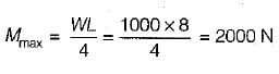
The maximum bending moment under a particular point load among a train of point loads crossing a simply Supported girder occurs at the location when that load is at - a)at mid span
- b)so placed that load point and the CG of the train of loads coincides
- c)at one-quarter span
- d)so placed that load point and the CG of the train of loads equi-distant from the mid span.
Correct answer is option 'D'. Can you explain this answer?
The maximum bending moment under a particular point load among a train of point loads crossing a simply Supported girder occurs at the location when that load is at
a)
at mid span
b)
so placed that load point and the CG of the train of loads coincides
c)
at one-quarter span
d)
so placed that load point and the CG of the train of loads equi-distant from the mid span.
 | Vertex Academy answered |
Position of Maximum Bending moment under a particular point load among a train of point loads:
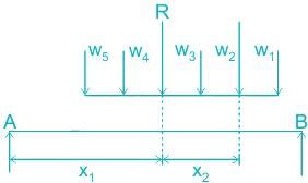
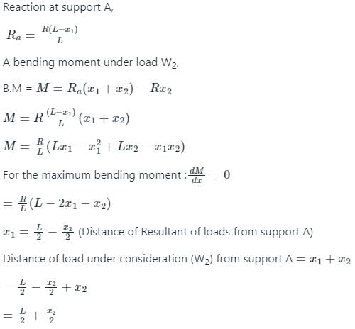
Conclusion: The maximum bending moment under a particular point load among a train of point loads crossing a simply Supported girder occurs at the location when that load is at a point so that the load and the resultant should be equidistant from the mid-span.
Conclusion: The maximum bending moment under a particular point load among a train of point loads crossing a simply Supported girder occurs at the location when that load is at a point so that the load and the resultant should be equidistant from the mid-span.
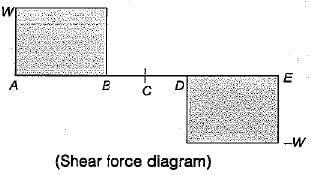
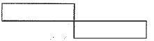
For the loaded beam shown in the figure, the correct shear force diagram is
- a)
- b)
- c)
- d)
Correct answer is option 'C'. Can you explain this answer?
For the loaded beam shown in the figure, the correct shear force diagram is
a)
b)
c)
d)
| | Ashish Chakraborty answered |
The shear force in the span BC will be zero. Hence the options A and B are incorrect. The shear force in the span AB and CD will be of opposite sign. Therefore, the option C is correct.
The rate of change of bending moment is equal to- a)shear force at that section
- b)deflection at that section
- c)loading at the section
- d)slope at that section
Correct answer is option 'A'. Can you explain this answer?
The rate of change of bending moment is equal to
a)
shear force at that section
b)
deflection at that section
c)
loading at the section
d)
slope at that section
| | Akanksha Mehta answered |
M = V · x
dM/dx = V
i.e. Rate of change of bending moment is shear force.
dM/dx = V
i.e. Rate of change of bending moment is shear force.
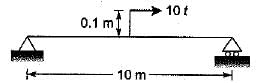
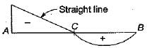
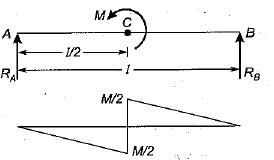
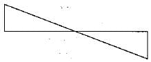
The correct shear force diagram for the beam shown in the figure is
- a)
- b)
- c)
- d)
Correct answer is option 'A'. Can you explain this answer?
The correct shear force diagram for the beam shown in the figure is
a)
b)
c)
d)
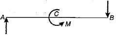
 | Mayuresh Patil answered |
Simply find the reaction Ra=-M/L and Rb = M/L
you will get Ra=-0.1t and Rb=0.1t
These forces will create a couple that will counteract the external couple.
Draw shear force considering these forces only. you will get a simple straight line in the negative direction.
Which one of the following portions of the loaded beam shown in the given figure is subjected to pure bending?
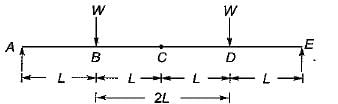
- a)AB
- b)DE
- c)AE
- d)BD
Correct answer is option 'D'. Can you explain this answer?
Which one of the following portions of the loaded beam shown in the given figure is subjected to pure bending?
a)
AB
b)
DE
c)
AE
d)
BD
| | Bhaskar Rane answered |
Since the given beam is loaded symmetrically, therefore the reactions at each suportwill be equal i.e. W
In section BD, shear force is zero. Hence this section subjected to pure bending.
In section BD, shear force is zero. Hence this section subjected to pure bending.
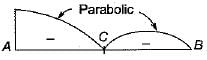
A propped cantilever beam shown in the figure given is having interna! hinge at its mid-span. Which one of the following is the shape of bending moment diagram for the given loading?
- a)
- b)
- c)
- d)
Correct answer is option 'D'. Can you explain this answer?
A propped cantilever beam shown in the figure given is having interna! hinge at its mid-span. Which one of the following is the shape of bending moment diagram for the given loading?
a)
b)
c)
d)
| | Nilesh Kapoor answered |
Due to hinge at C the part CB of beam be have s as simply supported beam. Thus reaction at B will be in upward direction and equals half of the load in span BC.
Span CA be haves as a cantilever beam. There fore B.M.D. will be sagging in BC and hogging in AC and it will be parabolic.
For a cantiiever B.M.D. will be as shown below.
Combining all the arguments answer will be (d) which is given with BM plotted on tension side.
Span CA be haves as a cantilever beam. There fore B.M.D. will be sagging in BC and hogging in AC and it will be parabolic.
For a cantiiever B.M.D. will be as shown below.
Combining all the arguments answer will be (d) which is given with BM plotted on tension side.
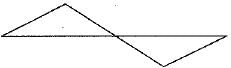
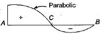
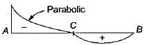
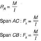
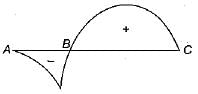
If the bending moment diagram for a simply suppoted beam is of the form as given in figure then the load acting on the beam is
- a)a concentrated force at C
- b)a uniformly distributed load over the whole length of the beam
- c)equal and opposite moments applied at A and B
- d)a moment applied at C
Correct answer is option 'D'. Can you explain this answer?
If the bending moment diagram for a simply suppoted beam is of the form as given in figure then the load acting on the beam is
a)
a concentrated force at C
b)
a uniformly distributed load over the whole length of the beam
c)
equal and opposite moments applied at A and B
d)
a moment applied at C
| | Maulik Das answered |

Span AC:
Span CB:
A simply supported beam is loaded as shown in the above figure below.
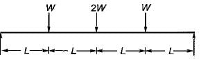
The maximum shear force in the beam will be - a)zero
- b)W
- c)2 W
- d)4 W
Correct answer is option 'C'. Can you explain this answer?
A simply supported beam is loaded as shown in the above figure below.
The maximum shear force in the beam will be
The maximum shear force in the beam will be
a)
zero
b)
W
c)
2 W
d)
4 W
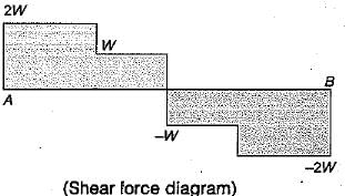
| | Aditi Sarkar answered |
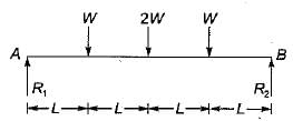
Taking moment about A = 0

R2 = 2W
But, ∑Fv = 0
⇒ W + 2W + W - R1 - R2 = 0
⇒ R1 = 4W - 2W = 2W
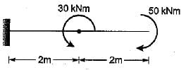
A cantilever beam is subjected to moments as shown in the given figure. The BM diagram for the beam will be
- a)
- b)
- c)
- d)

Correct answer is option 'A'. Can you explain this answer?
A cantilever beam is subjected to moments as shown in the given figure. The BM diagram for the beam will be
a)
b)
c)
d)
| | Anuj Chakraborty answered |
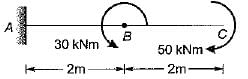
The bending moment due to 50 kNm moment would be hogging. Similarly the bending moment due to 30 kNm would be sagging. Therefore the bending moment diagram is,
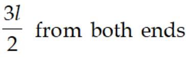
A simply supported beam of span 'L' carrying a UDL of w per unit length. If the beam is propped at its centre then in bending moment diagram, the bending moment is zero at a distance of - a)
- b)
- c)
- d)
Correct answer is option 'C'. Can you explain this answer?
A simply supported beam of span 'L' carrying a UDL of w per unit length. If the beam is propped at its centre then in bending moment diagram, the bending moment is zero at a distance of
a)
b)
c)
d)
 | Engineers Adda answered |
From compatibilty equation, deflection due to R + deflection to w = 0
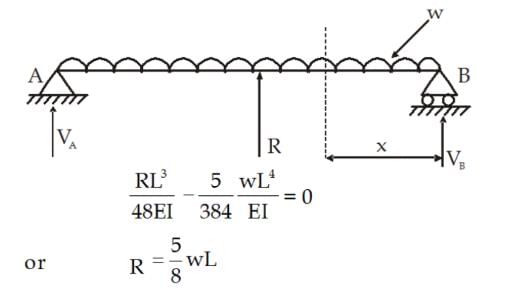
Next, from the overall equilibrium (balancing the total vertical forces on the beam):
VA + R + VC = wL
2V + 5/8 wL = wL [from symmetry VA = VC = V ]
Thus,
V = (3wL) / (8×2) = (3wL) / 16.
V = (3wL) / (8×2) = (3wL) / 16.
Now, let at a section x distance apart from support B, the bending moment at the section is:
Mx = (3wL / 16) × x - (wx²) / 2 = 0.
Mx = (3wL / 16) × x - (wx²) / 2 = 0.
Thus,
x / 2 = 3 / 16 L
Therefore,
x = 3L / 8 (from both ends).
x / 2 = 3 / 16 L
Therefore,
x = 3L / 8 (from both ends).
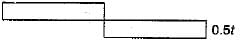
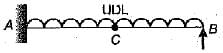
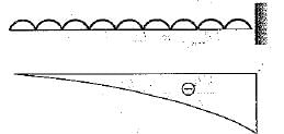
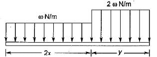
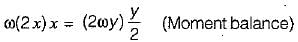
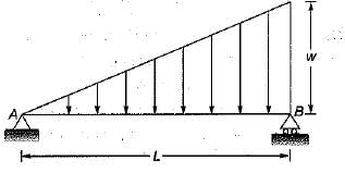
The shear force along the beam shown in the figure is
- a)Zero
- b)Uniform
- c) Uniformly varying
- d)Concentrated at A and B only
Correct answer is option 'C'. Can you explain this answer?
The shear force along the beam shown in the figure is
a)
Zero
b)
Uniform
c)
Uniformly varying
d)
Concentrated at A and B only
| | Engineers Adda answered |
C) Uniformly varying:
Because the shear force is determined by the location of the load and varies from one end to the point of load application.
Because the shear force is determined by the location of the load and varies from one end to the point of load application.
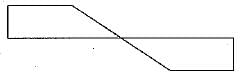
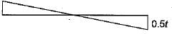
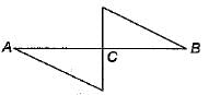
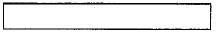
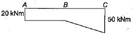
The BM diagram of the beam shown in figure is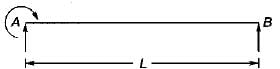
- a)a rectangle
- b)a triangle
- c)a trapezium
- d)a parabola
Correct answer is option 'B'. Can you explain this answer?
The BM diagram of the beam shown in figure is
a)
a rectangle
b)
a triangle
c)
a trapezium
d)
a parabola
| | Poulomi Khanna answered |
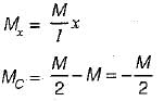
Taking moments about A. We get
M - R2 + L = 0
⇒ R2 = M/L
Since these is no vertical loading hence the reactions are equal and oposite.
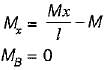
Bending moment is given by

M - R2 + L = 0
⇒ R2 = M/L
Since these is no vertical loading hence the reactions are equal and oposite.
Bending moment is given by
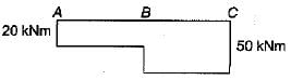
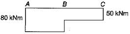
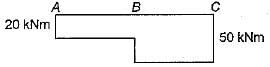
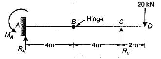
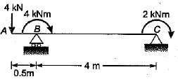
The fixed end moment MA of the beam shown in the given figure is
- a)+40 kNm
- b)-40 kNm
- c)+80 kNm
- d)-80 kNm
Correct answer is option 'B'. Can you explain this answer?
The fixed end moment MA of the beam shown in the given figure is
a)
+40 kNm
b)
-40 kNm
c)
+80 kNm
d)
-80 kNm
| | Mahesh Nair answered |
∑FV = 0
⇒ RA + RC = 20
MB = 0 [from right]
∴ RC x 4 - 20 x 6 = 0
⇒ Rc x 4 = 20 x 6
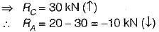
MB = 0 [from left]
RA x 4 - MA = 0
⇒ MA = RA x 4 = -10 x 4
= - 40 kNm
The fixed end moment at A will be in clockwise direction, opposite to the direction shown in the figure.
∴ MA = -40 kNm
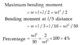
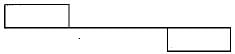
A simply supported beam with equal overhang ori both sides is loaded as shown in the figure. If the bending moment at mid-span is zero, then the percentage overhang on each side will be

- a)33.3
- b)25
- c)20
- d)15
Correct answer is option 'B'. Can you explain this answer?
A simply supported beam with equal overhang ori both sides is loaded as shown in the figure. If the bending moment at mid-span is zero, then the percentage overhang on each side will be
a)
33.3
b)
25
c)
20
d)
15
| | Arnab Saini answered |
Let the overhang percentage in 100p.
So overhang = pl
The shear force diagram will be,

For B.M. at mid point to be zero, area of shear force diagram under (1) should be equal to that of (2),

So overhang = pl
The shear force diagram will be,
For B.M. at mid point to be zero, area of shear force diagram under (1) should be equal to that of (2),
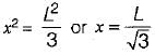
For the simply supported beam, shown in the figure below at what distance from the support A is the shear force zero?
- a)L/4
- b)L/3
- c)L/2
- d)L/√3
Correct answer is option 'D'. Can you explain this answer?
For the simply supported beam, shown in the figure below at what distance from the support A is the shear force zero?
a)
L/4
b)
L/3
c)
L/2
d)
L/√3
| | Rajdeep Gupta answered |
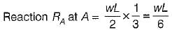
Let the point of zero shear force occur at section X-Xfrom left support A
∴ Shear force at X-X
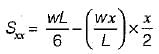
∴ For zero shear force we have,

∴
In a continuous curve of bending moment, the point of zero bending moment, where it changes sign is called- a)the point of inflextion
- b)the point of contra-flexure
- c)the point of a virtual hinge
- d)all of the above
Correct answer is option 'D'. Can you explain this answer?
In a continuous curve of bending moment, the point of zero bending moment, where it changes sign is called
a)
the point of inflextion
b)
the point of contra-flexure
c)
the point of a virtual hinge
d)
all of the above
| | Divya Banerjee answered |
Explanation:
Therefore, the correct answer is option 'D' - all of the above.
- Continuous curve of bending moment: A bending moment diagram is a graphical representation of the variation of bending moment along the length of a beam under loading.
- Point of zero bending moment: It is the point where the bending moment changes sign from positive to negative or vice versa.
- Point of inflexion: It is a point on a curve where the curvature changes sign. In a bending moment diagram, the point of inflexion is the point where the second derivative of the bending moment curve changes sign.
- Point of contra-flexure: It is a point on a beam where the bending moment is zero but the curvature is not zero. In other words, it is a point where the beam changes from being concave upwards to concave downwards or vice versa.
- Point of a virtual hinge: It is a point on a beam where the bending moment is zero and the shear force is not zero. In other words, it is a point where the beam has a zero moment but is still subjected to a transverse force.
- All of the above: The point of zero bending moment can be referred to as any of the above terms depending on the context of the problem.
Therefore, the correct answer is option 'D' - all of the above.
The beam is loaded as shown in figure. Select the correct BM diagram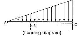
- a)

- b)
- c)
- d)
Correct answer is option 'D'. Can you explain this answer?
The beam is loaded as shown in figure. Select the correct BM diagram
a)
b)
c)
d)
| | Pallabi Tiwari answered |
BMD will be of 2nd degree, so the correct answer is (d).
Chapter doubts & questions for Shear Force & Bending Moment Diagrams (SFD & BMD) - Solid Mechanics 2026 is part of Mechanical Engineering exam preparation. The chapters have been prepared according to the Mechanical Engineering exam syllabus. The Chapter doubts & questions, notes, tests & MCQs are made for Mechanical Engineering 2026 Exam. Find important definitions, questions, notes, meanings, examples, exercises, MCQs and online tests here.
Chapter doubts & questions of Shear Force & Bending Moment Diagrams (SFD & BMD) - Solid Mechanics in English & Hindi are available as part of Mechanical Engineering exam. Download more important topics, notes, lectures and mock test series for Mechanical Engineering Exam by signing up for free.
Solid Mechanics33 videos|85 docs|29 tests |