


All Exams > Electrical Engineering (EE) > Power Systems > All Questions
All questions of Distribution Systems, Cables & Insulators for Electrical Engineering (EE) Exam
What is the percentage saving in feeder copper if the line voltage in a 2-wire DC systems is raised from 100 V to 200 V for the same power transmitted over the same power distance and having the same power loss?- a)25 %
- b)75 %
- c)50 %
- d)100 %
Correct answer is option 'B'. Can you explain this answer?
What is the percentage saving in feeder copper if the line voltage in a 2-wire DC systems is raised from 100 V to 200 V for the same power transmitted over the same power distance and having the same power loss?
a)
25 %
b)
75 %
c)
50 %
d)
100 %
| | Bibek Saha answered |
Percentage saving in feeder copper:
To calculate the percentage saving in feeder copper, we need to compare the amount of copper required for the original voltage (100 V) with the amount required for the new voltage (200 V).
Power transmitted:
Given that the power transmitted remains the same, we can calculate the power using the formula:
Power = Voltage * Current
Since the power is the same, we can write:
Power1 = Power2
Power loss:
The power loss in a transmission line is given by the formula:
Power loss = I^2 * R
Since the power loss remains the same, we can write:
Power loss1 = Power loss2
Calculating the current:
To calculate the current, we can rearrange the power formula:
Current = Power / Voltage
Since the power is the same, we can write:
Current1 = Current2
Calculating the resistance:
We know that the power loss in the transmission line is given by the formula:
Power loss = I^2 * R
Rearranging the formula, we get:
R = Power loss / I^2
Since the power loss is the same and the current is the same, we can write:
Resistance1 = Resistance2
Calculating the amount of copper:
The amount of copper required for a transmission line is directly proportional to the resistance. Therefore, if the resistance is the same, the amount of copper required will also be the same.
Calculating the percentage saving:
To calculate the percentage saving, we can use the formula:
Percentage saving = (Copper1 - Copper2) / Copper1 * 100
Since the amount of copper required is the same for both voltages, we have:
Percentage saving = (Copper1 - Copper1) / Copper1 * 100
= 0 / Copper1 * 100
= 0
Therefore, there is no percentage saving in feeder copper when the line voltage is raised from 100 V to 200 V for the same power transmitted over the same power distance and having the same power loss. The correct answer is option 'B' - 75%.

Cables used for underground services from 33 kV to 60 kV are:- a)extra high-tension cables
- b)high tension cables
- c)super tension cables
- d)extra super voltage cables
Correct answer is option 'A'. Can you explain this answer?
Cables used for underground services from 33 kV to 60 kV are:
a)
extra high-tension cables
b)
high tension cables
c)
super tension cables
d)
extra super voltage cables
| | Sanaya Basu answered |
Underground cables are used to transmit electrical power from one location to another. They are commonly used in urban areas where overhead lines may not be feasible due to space constraints or aesthetic considerations. When it comes to underground services with voltage levels ranging from 33 kV to 60 kV, the correct type of cable to use is known as extra high-tension cables.
Extra high-tension cables, also known as EHT cables, are specifically designed to handle higher voltage levels compared to other types of cables. These cables are designed to have a higher insulation level and are capable of withstanding higher electrical stresses.
Here are some key points about extra high-tension cables:
1. Insulation: The insulation used in EHT cables is designed to withstand the high voltages present in these systems. The insulation material used is typically a special grade of cross-linked polyethylene (XLPE) or ethylene propylene rubber (EPR), which has excellent electrical properties.
2. Conductor: The conductors used in EHT cables are usually made of copper or aluminum. These conductors are designed to have a large cross-sectional area to handle the high current carrying capacity required for transmitting power at higher voltages.
3. Shielding: EHT cables are often equipped with shielding layers to protect the cable from external electrical interference and to minimize the electric field outside the cable. The shielding layers are made of metallic tapes or wires that are wrapped around the insulation.
4. Jacketing: The outermost layer of the cable is known as the jacket, which provides mechanical protection to the cable against moisture, chemicals, and physical damage. The jacketing material used is typically a thermoplastic material such as polyvinyl chloride (PVC) or high-density polyethylene (HDPE).
Overall, extra high-tension cables are specifically designed to handle the higher voltage levels of 33 kV to 60 kV. These cables have higher insulation levels, larger conductors, shielding layers, and protective jackets to ensure safe and reliable transmission of electrical power underground.
Screened cables can be used for voltages:- a)up to 11 kV
- b)11 kV to 33 kV
- c)33 kV to 66 kV
- d)66 kV to 132 kV
Correct answer is option 'C'. Can you explain this answer?
Screened cables can be used for voltages:
a)
up to 11 kV
b)
11 kV to 33 kV
c)
33 kV to 66 kV
d)
66 kV to 132 kV
 | Machine Experts answered |
- In practice, underground cables are generally required to deliver 3-phase power. For the purpose, either three-core cable or three single-core cables may be used.
- For voltages upto 66 kV, 3-core cable (i.e., multi-core construction) is preferred due to economic reasons.
- However, for voltages beyond 66 kV, 3-core-cables become too large and unwieldy and, therefore, single-core cables are used.
The following types of cables are generally used for 3-phase service:
- Belted cables — up to 11 kV
- Screened cables — from 22 kV to 66 kV
- Pressure cables — beyond 66 kV.
Screened cables: These cables are meant for use up to 33 kV, but in particular cases, their use may be extended to operating voltages up to 66 kV. Two principal types of screened cables are H type cables and S.L. type cables.
Consider the following statements:
1. AAC (All Aluminium conductors) are universaly employed for feeders as well as distributors.
2. The conductor size for a feeder is mainly governed by the permissible voltage drop in the line.
Which of the above statement(s) is/are true?- a)1 only
- b)1 and 2
- c)none
- d)2 only
Correct answer is option 'C'. Can you explain this answer?
Consider the following statements:
1. AAC (All Aluminium conductors) are universaly employed for feeders as well as distributors.
2. The conductor size for a feeder is mainly governed by the permissible voltage drop in the line.
Which of the above statement(s) is/are true?
1. AAC (All Aluminium conductors) are universaly employed for feeders as well as distributors.
2. The conductor size for a feeder is mainly governed by the permissible voltage drop in the line.
Which of the above statement(s) is/are true?
a)
1 only
b)
1 and 2
c)
none
d)
2 only
| | Isha Singh answered |
ACSR conductors are universally employed for distribution systems (feeders as well as distributors), AAC can be used for distribution purpose provided the spans are small.
Hence, statement-1 is false.
The conductor size for a feeder is mainly governed by current carrying capacity and overall economy. Hence, 2 is also a false statement.
Hence, statement-1 is false.
The conductor size for a feeder is mainly governed by current carrying capacity and overall economy. Hence, 2 is also a false statement.
A 2-wire DC distributor cable 800 m long is loaded with 1 A/m. Resistance of each conductor is 0.05 Ω/km. Calculate the maximum voltage drop if the distributor is fed from both ends with equal voltages of 220 V.- a)2 V
- b)8 V
- c)16 V
- d)4 V
Correct answer is option 'B'. Can you explain this answer?
A 2-wire DC distributor cable 800 m long is loaded with 1 A/m. Resistance of each conductor is 0.05 Ω/km. Calculate the maximum voltage drop if the distributor is fed from both ends with equal voltages of 220 V.
a)
2 V
b)
8 V
c)
16 V
d)
4 V
| | Shanaya Mehta answered |
To calculate the maximum voltage drop in the 2-wire DC distributor cable, we need to consider the resistance of the cable and the current flowing through it.
Given:
Length of the cable (L) = 800 m
Current per unit length (I) = 1 A/m
Resistance per unit length (R) = 0.05 Ω/km
Voltage at each end of the cable (V) = 220 V
1. Calculate the total resistance of the cable:
The resistance of the cable can be calculated using the formula:
Resistance (R) = Resistance per unit length (R') * Length of the cable (L)
In this case, R' = 0.05 Ω/km and L = 800 m.
So, R = 0.05 Ω/km * 800 m = 40 Ω
2. Calculate the total current flowing through the cable:
The total current flowing through the cable can be calculated using the formula:
Total current (I_total) = Current per unit length (I) * Length of the cable (L)
In this case, I = 1 A/m and L = 800 m.
So, I_total = 1 A/m * 800 m = 800 A
3. Calculate the voltage drop across the cable:
The voltage drop across the cable can be calculated using Ohm's Law:
Voltage drop (V_drop) = Resistance (R) * Total current (I_total)
In this case, R = 40 Ω and I_total = 800 A.
So, V_drop = 40 Ω * 800 A = 32000 V
4. Determine the maximum voltage drop:
Since the cable is fed from both ends with equal voltages, the maximum voltage drop will occur when the cable is fully loaded. In this case, the maximum voltage drop will be half of the total voltage drop.
Maximum voltage drop = V_drop / 2 = 32000 V / 2 = 16000 V
Therefore, the maximum voltage drop in the 2-wire DC distributor cable is 16000 V.
The correct answer is option C) 16 V.
In a two-wire system, the voltage across the supply end is maintained at 500 V. The line is 4 km long. If the full-load current is 15 A, what should be the booster voltage and output so that the distant voltage can also be 500 V?Take the resistance of the cable to be 0.5 ohm/km.- a)224 W
- b)260 W
- c)450 W
- d)120 W
Correct answer is option 'C'. Can you explain this answer?
In a two-wire system, the voltage across the supply end is maintained at 500 V. The line is 4 km long. If the full-load current is 15 A, what should be the booster voltage and output so that the distant voltage can also be 500 V?
Take the resistance of the cable to be 0.5 ohm/km.
a)
224 W
b)
260 W
c)
450 W
d)
120 W
| | Pooja Patel answered |
We Have,
Resistance of cable is 0.5 ohm/km
Hence, total Resistance of 4 km long cable (R) = 0.5 × 4 = 2 Ω
Load Current (I) = 15 A
So total Voltage drop in the cable = IR = 15 × 2 = 30 volts
Total Power Loss (P) = I2R
⇒ P = I2R = 152 × 2 = 225 × 2 = 450 W
The insulation resistance of a cable of 10 km length is 1 MΩ. The resistance for a length of 40 km is- a)1 MΩ
- b)4 MΩ
- c)0.25 MΩ
- d)Can’t be determined
Correct answer is option 'C'. Can you explain this answer?
The insulation resistance of a cable of 10 km length is 1 MΩ. The resistance for a length of 40 km is
a)
1 MΩ
b)
4 MΩ
c)
0.25 MΩ
d)
Can’t be determined
| | Tanishq Majumdar answered |
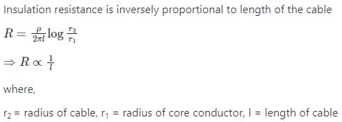
l1 = 10 km, R1 = 1 MΩ, l2 = 40 km

1/R2 = 40/10
R2 = 1/4 = 0.25 MΩ
Which among the following cable are generally suited for the voltage up to 11 kV?- a)Belted cabless
- b)Screened cables
- c)Pressure cables
- d)None of these
Correct answer is option 'A'. Can you explain this answer?
Which among the following cable are generally suited for the voltage up to 11 kV?
a)
Belted cabless
b)
Screened cables
c)
Pressure cables
d)
None of these
| | Nilanjan Saini answered |
Introduction:
In electrical engineering, cables are used to transmit electrical power from one point to another. Different types of cables are used depending on the voltage level and application requirements. The question asks about the type of cable generally suited for voltage up to 11 kV.
Belted Cables:
- Belted cables are one of the types of cables used for high voltage applications.
- These cables consist of multiple insulated conductors arranged in a circular configuration and held together by a metallic or non-metallic belt.
- The belt provides mechanical strength and protects the conductors from external influences.
- Belted cables are commonly used for medium voltage applications up to 11 kV.
- They are suitable for both underground and overhead installations.
Screened Cables:
- Screened cables, also known as shielded cables, are another type of cables used for high voltage applications.
- These cables have an additional layer of metallic shielding around the insulated conductors.
- The shielding layer is usually made of copper or aluminum and provides protection against electromagnetic interference.
- Screened cables are commonly used in high voltage applications, typically above 11 kV.
- They are suitable for underground installations and are commonly used in power distribution systems.
Pressure Cables:
- Pressure cables, also known as pipe-type cables or fluid-filled cables, are a different type of cables used for high voltage applications.
- These cables consist of insulated conductors enclosed in a fluid-filled pipe or tube.
- The fluid, usually oil, provides insulation and cooling for the conductors.
- Pressure cables are commonly used for very high voltage applications, typically above 66 kV.
- They are suitable for both underground and underwater installations.
Conclusion:
Based on the given options, belt cables are generally suited for the voltage up to 11 kV. This type of cable is commonly used for medium voltage applications and provides the necessary insulation and mechanical strength. Screened cables and pressure cables are typically used for higher voltage levels.
Dielectric strength of rubber is around- a)3 kV/mm
- b)10 kV/mm
- c)30 kV/mm
- d)300 kV/mm
Correct answer is option 'C'. Can you explain this answer?
Dielectric strength of rubber is around
a)
3 kV/mm
b)
10 kV/mm
c)
30 kV/mm
d)
300 kV/mm
| | Arindam Sengupta answered |
Dielectric Strength of Rubber
Dielectric strength is a measure of the maximum electric field a material can withstand without breaking down. In the case of rubber, its dielectric strength is typically around 30 kV/mm.
Explanation:
- Dielectric Strength Definition: Dielectric strength is the maximum electric field a material can withstand without experiencing electrical breakdown. It is an important property in determining the insulating capabilities of a material.
- Rubber as an Insulator: Rubber is often used as an insulating material in electrical applications due to its flexibility and resistance to electricity. It can effectively prevent the flow of electrical current when used as an insulator.
- Dielectric Strength of Rubber: The dielectric strength of rubber is around 30 kV/mm, which means it can withstand high electric fields before breaking down. This makes rubber a suitable material for insulation in various electrical and electronic devices.
- Applications: Rubber with its dielectric strength of 30 kV/mm finds applications in cables, wires, electrical components, and insulating coatings where high voltage protection is required.
- Importance: Understanding the dielectric strength of rubber is crucial in designing and selecting appropriate materials for electrical insulation to ensure safety and efficiency in electrical systems.
In conclusion, the dielectric strength of rubber being around 30 kV/mm makes it a reliable insulating material for various electrical applications where high voltage protection is necessary.
Which of the following is the main field of application of pin type insulator?- a)Distribution system
- b)Transmission system
- c)Transmission and distribution system
- d)EHV transmission system
Correct answer is option 'A'. Can you explain this answer?
Which of the following is the main field of application of pin type insulator?
a)
Distribution system
b)
Transmission system
c)
Transmission and distribution system
d)
EHV transmission system
| | Zoya Sharma answered |
Pin type insulator become very bulky and cumbersome when designed for higher voltage. Pin insulators beyond 50,000 Volts becomes uneconomical. the modern practice is not to use pin type insulator SBI on 33kv so use of pin insulator is limited to distribution level voltage.
Suspension insulator are made up of _____________- a)glass
- b)porcelain
- c)steatite
- d)epoxy resin
Correct answer is option 'B'. Can you explain this answer?
Suspension insulator are made up of _____________
a)
glass
b)
porcelain
c)
steatite
d)
epoxy resin
| | Pooja Patel answered |
Suspension insulators consist of a number of porcelain disks flexibly connected in series by metal links in the form of Strings. Glass is used for making pin type insulators.
Voltage distribution across disc of strings of suspension insulator assembly is ______- a)same for all disks
- b)maximum for unit nearest to the line
- c)maximum for unit nearest to the tower
- d)equal to transmission line voltage rating
Correct answer is option 'B'. Can you explain this answer?
Voltage distribution across disc of strings of suspension insulator assembly is ______
a)
same for all disks
b)
maximum for unit nearest to the line
c)
maximum for unit nearest to the tower
d)
equal to transmission line voltage rating
| | Zoya Sharma answered |
Thee voltage between line conductor and Earth is not distributed uniformly across individual disks. The unit nearest the conductor has the maximum value across it. The figure progressively decreases as the unit nearest the cross on is approach.
If a string of suspension insulator has three units, each can withstand a maximum 11 KV and total string can withstand 25.76 KV. What is the string efficiency?- a)234.1%
- b)46.3%
- c)68.75%
- d)78%
Correct answer is option 'D'. Can you explain this answer?
If a string of suspension insulator has three units, each can withstand a maximum 11 KV and total string can withstand 25.76 KV. What is the string efficiency?
a)
234.1%
b)
46.3%
c)
68.75%
d)
78%
| | Ameya Nambiar answered |
Suspension Insulators
Suspension insulators are widely used in electrical power systems to support overhead transmission lines. They are designed to provide insulation and mechanical support to the conductors, while also preventing electrical leakage and flashover.
String Efficiency
The string efficiency of a suspension insulator string is a measure of its ability to distribute the applied voltage equally across all the insulator units. It is given by the ratio of the maximum voltage that can be applied to the entire string to the sum of the maximum voltages that each unit can withstand individually.
Given Parameters
Number of units in the string (n) = 3
Maximum voltage withstand by each unit (V) = 11 KV
Total voltage withstand by the string (Vt) = 25.76 KV
Calculating String Efficiency
The maximum voltage that can be applied to the entire string is equal to the maximum voltage withstand by each unit multiplied by the number of units in the string.
Maximum voltage of the string (Vs) = V * n = 11 KV * 3 = 33 KV
The string efficiency (SE) is then given by the ratio of the total voltage withstand by the string to the maximum voltage of the string.
SE = (Vt / Vs) * 100 = (25.76 KV / 33 KV) * 100 = 0.78 * 100 = 78%
Therefore, the string efficiency of the suspension insulator string is 78%.
Conclusion
In this question, we were given the number of units in the suspension insulator string, the maximum voltage withstand by each unit, and the total voltage withstand by the string. By calculating the maximum voltage of the string and applying the formula for string efficiency, we determined that the string efficiency is 78%.
A 2-wire d.c. distributor 200 meters long is uniformly loaded with 2A/meter resistance of a single wire is 0.3 Ω/km. If the distributor is fed at one end, calculate the maximum voltage drop- a)10 volt
- b)12 volt
- c)24 volt
- d)None of these
Correct answer is option 'B'. Can you explain this answer?
A 2-wire d.c. distributor 200 meters long is uniformly loaded with 2A/meter resistance of a single wire is 0.3 Ω/km. If the distributor is fed at one end, calculate the maximum voltage drop
a)
10 volt
b)
12 volt
c)
24 volt
d)
None of these
| | Pooja Patel answered |
Concept:
In a uniformly loaded distributor fed at one end, the maximum total voltage drop = IR/2
In a uniformly loaded distributor fed at both ends, the maximum total voltage drop = IR/8
The maximum voltage drop in the case of uniformly loaded distributor fed at both ends is one-fourth of the maximum voltage drop in the case of uniformly loaded distributor fed at one end.
Calculation:
Length of distributor = 200 m = 0.2 km
Current supplied by distributor = 2 amperes/meter
Total current supplied by distributor (I) = 200 × 2 = 400 A
The resistance of single wire = 0.3 Ω/km
Total resistance = 0.3 × 0.2 = 0.06 Ω
Maximum voltage drop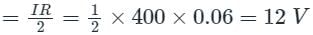
Which of the following material is not used for overhead line insulators?- a)Porcelain
- b)Glass
- c)PVC
- d)Steatite
Correct answer is option 'C'. Can you explain this answer?
Which of the following material is not used for overhead line insulators?
a)
Porcelain
b)
Glass
c)
PVC
d)
Steatite
| | Zoya Sharma answered |
In addition to high insulation resistance and high relative permittivity, overhead line insulators must have high mechanical strength to bear the weight of line insulators, wind stress and ice loading if any. PVC have good insulation resistance but it does not have such mechanical strength so it is not suitable for overhead line insulators.
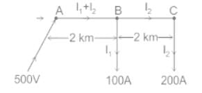
Fig. below shows a 2 wire DC distributor cable AC of 4 km long supplying loads of 100 A and 200 A at distances of 2 km and 4 km from A. The feeder is fed at point A with a voltage of 500 V. The voltage available at the farthest point in the system is ______.(Assume conductor resistance per km as 0.02 Ω).

- a)470 V
- b)460 V
- c)476 V
- d)480 V
Correct answer is option 'B'. Can you explain this answer?
Fig. below shows a 2 wire DC distributor cable AC of 4 km long supplying loads of 100 A and 200 A at distances of 2 km and 4 km from A. The feeder is fed at point A with a voltage of 500 V. The voltage available at the farthest point in the system is ______.
(Assume conductor resistance per km as 0.02 Ω).
a)
470 V
b)
460 V
c)
476 V
d)
480 V
 | Pioneer Academy answered |
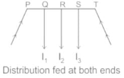
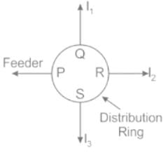
On the basis of how DC distributors are fed by the feeders, they are classified as:
- Distributor fed at one end
- Distributor fed at both ends
- Distributor fed at the centre.
- Ring distributor.
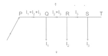
Now the type of distribution given in the question is of type “Distributor fed at one end”.
- In this type of feeding, the distributor is connected to the supply at one end and loads are taken at different points along the length of the distributor.
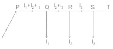
- In the above figure end P is also called singly fed distributor and loads I1, I2 and I3 tapped off at points Q, R, S respectively.
Points to remember in this type of distribution:
- The current in the various sections of the distributor away from the feeding point goes on decreasing. Thus the current in the section PQ is more than current in the section QR and the current in the section QR is more than current in section RS.
- The voltage across the loads away from the feeding point goes on decreasing. Therefore minimum voltage occurs at point S.
- In case a fault occurs at/on any section of the distributor, the whole distributor will have to be disconnected from the supply mains.
Calculations:
Given- conductor resistance per km = 0.02 Ω
But in 2 wire DC distributor system 2 conductors are present
∴ Resistance per km for 2 wire DC distributor = 0.02 × 2 = 0.04 Ω
∴ Resistance of section AB = 0.04 × 2 = 0.08 Ω (RAB)
∴ Resistance of section BC = 0.04 × 2 = 0.08 Ω (RBC)
Also, I2 = 200 A, I1 = 100 A
∴ Current in section AB = I1 + I2 = 100 + 200 = 300 A
∴ current in section BC = I2 = 200 A
i.e. IAB = 300 A, IBC = 200 A
Now, Voltage available at load point B
VB = Voltage at A – Voltage drop in AB
VB = 500 V – IAB × RAB
VB = 500 V – (300 × 0.08) V
VB = (500 - 24) V
VB = 476 V
Now, voltage available at point C
VC = voltage at B – voltage drop in BC
VC = 476 V – IBC × RBC
VC = 476 V – (200 × 0.08) V
VC = 476 V – 16 V
VC = 460 V
Therefore the voltage available at the farthest point (C) in the system is 460 V.
Note:
There are a few advantages of other types of the distribution system.
- In this type of distribution, if a fault occurs on any feeding point of the distributor or on any section of the distributor, the continuity of the supply is maintained from the other operating feeding point.
- Also the area of cross-section required for doubly-fed distributors is much less than that of a singly fed distributor.
Fig. Distributor fed at the center
- Distributor fed at the center is equivalent to two singly fed distributors, each distributor having a common feeding point and length equal to half of the total length.
- In-ring main distribution, the distributor is in the form of a closed ring. It is equivalent to a straight distributor fed at both ends with equal voltages, where the two ends being brought together to form a closed ring.
- The distributor ring may be fed at one or more than one point.
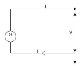
For the figure shown, having a 2-wire dc system where mid point is earthed, having resistance of 20 ohms, with a power transmitted of 5 MW at the voltage level of 440 kV.
The power loss of the distribution system will be __________
- a)5165 W
- b)515 kW
- c)10330 W
- d)2583 W
Correct answer is option 'A'. Can you explain this answer?
For the figure shown, having a 2-wire dc system where mid point is earthed, having resistance of 20 ohms, with a power transmitted of 5 MW at the voltage level of 440 kV.
The power loss of the distribution system will be __________
The power loss of the distribution system will be __________
a)
5165 W
b)
515 kW
c)
10330 W
d)
2583 W
| | Pioneer Academy answered |
I = P/V = 5000000/440000 = 11.36 A
Power loss = 2I2 * R = 2 * 11.362 * 20 = 5165 W.
Power loss = 2I2 * R = 2 * 11.362 * 20 = 5165 W.
Which type of transmission system is NOT considered for a DC system?- a)DC two wires with midpoint earthed
- b)DC three wires
- c)DC two wires
- d)DC four wires with line earthed
Correct answer is option 'D'. Can you explain this answer?
Which type of transmission system is NOT considered for a DC system?
a)
DC two wires with midpoint earthed
b)
DC three wires
c)
DC two wires
d)
DC four wires with line earthed
| | Ashwin Mukherjee answered |
DC Transmission Systems
DC Four Wires with Line Earthed
DC four wires with line earthed is not considered for a DC system. In a DC transmission system, the most commonly used configurations are DC two wires with midpoint earthed, DC three wires, and DC two wires. However, a DC four wires system with line earthed is not typically employed for DC transmission.
Explanation
- DC two wires with midpoint earthed: This configuration involves two conductors with a midpoint earth connection. It is commonly used for long-distance DC transmission as it helps in reducing losses and improving system reliability.
- DC three wires: In this setup, three conductors are used for DC transmission. It allows for better load balancing and fault tolerance compared to a two-wire system.
- DC two wires: A simple two-wire DC system is used for shorter transmission distances or in applications where a more complex configuration is not necessary.
- DC four wires with line earthed: This configuration involves four conductors with one of the lines being earthed. While it is possible to have a four-wire DC system, it is not commonly used and considered less practical compared to other configurations.
In summary, DC four wires with line earthed is not typically considered for a DC transmission system due to its limited advantages and practicality compared to other configurations.
Suspension type insulator are subjected to ______________- a)tensile stress
- b)compressive stress
- c)tensile and compressive stress
- d)depends on its use
Correct answer is option 'A'. Can you explain this answer?
Suspension type insulator are subjected to ______________
a)
tensile stress
b)
compressive stress
c)
tensile and compressive stress
d)
depends on its use
| | Pooja Patel answered |
Suspension type insulator hangs from the cross arms of the suspending supporting structure. The line conductor is attached to its lower end hence the load of the conductor causes tensile stress on the suspension insulator.
A transmission and distribution engineer needed to design the sub transmission substation. The tapping component needed will be ______.- a)feeder
- b)distributor
- c)transmitter
- d)tap-changing transformer
Correct answer is option 'A'. Can you explain this answer?
A transmission and distribution engineer needed to design the sub transmission substation. The tapping component needed will be ______.
a)
feeder
b)
distributor
c)
transmitter
d)
tap-changing transformer
| | Zoya Sharma answered |
For the sub transmission level, there is no tapping at various level does not take place. For this a feeder is used.
A _________ distribution system is more reliable than the ______ distribution system.- a)parallel, radial
- b)parallel, ring
- c)radial, parallel
- d)ring, parallel
Correct answer is option 'A'. Can you explain this answer?
A _________ distribution system is more reliable than the ______ distribution system.
a)
parallel, radial
b)
parallel, ring
c)
radial, parallel
d)
ring, parallel
| | Pooja Patel answered |
A parallel distribution system has two end feeding and an alternative of parallel line, so in case there is a fault, the isolator can isolate the faulty part and let the healthy system operate.
How many types of DC distributions system are present solely based on the way they are fed by feeders?- a)3
- b)4
- c)5
- d)6
Correct answer is option 'B'. Can you explain this answer?
How many types of DC distributions system are present solely based on the way they are fed by feeders?
a)
3
b)
4
c)
5
d)
6
 | Cstoppers Instructors answered |
On the basis of how DC distributors are fed by the feeders, they are classified as:
- Distributor fed at one end
- Distributor fed at both ends
- Distributor fed at the centre.
- Ring distributor.
Now the type of distribution given in the question is of type “Distributor fed at one end”.
- In this type of feeding, the distributor is connected to the supply at one end and loads are taken at different points along the length of the distributor.
- In the above figure end P is also called singly fed distributor and loads I1, I2 and I3 tapped off at points Q, R, S respectively.
Points to remember in this type of distribution:
- The current in the various sections of the distributor away from the feeding point goes on decreasing. Thus the current in the section PQ is more than current in the section QR and the current in the section QR is more than current in section RS.
- The voltage across the loads away from the feeding point goes on decreasing. Therefore minimum voltage occurs at point S.
- In case a fault occurs at/on any section of the distributor, the whole distributor will have to be disconnected from the supply mains.
Which of the following insulator is similar to pin type insulator?- a)Suspension insulator
- b)Post insulator
- c)Strain insulator
- d)Shackle insulator
Correct answer is option 'B'. Can you explain this answer?
Which of the following insulator is similar to pin type insulator?
a)
Suspension insulator
b)
Post insulator
c)
Strain insulator
d)
Shackle insulator
| | Pooja Patel answered |
Post insulators are very similar to pin type insulator, but has a metal base with a metal cap so that more than one unit can be mounted in series. Suspensions train and shackle insulators are completely different from pin type insulator on the basis of construction.
A DC 2-wire system with mid-point earthed having cross-sectional area of each conductor be ‘a’ and resistance ‘R1’. If this is replaced by monopolar system, then saving of copper will be ______- a)1/2
- b)1/4
- c)2
- d)4
Correct answer is option 'A'. Can you explain this answer?
A DC 2-wire system with mid-point earthed having cross-sectional area of each conductor be ‘a’ and resistance ‘R1’. If this is replaced by monopolar system, then saving of copper will be ______
a)
1/2
b)
1/4
c)
2
d)
4
| | Pioneer Academy answered |
Let the power losses remain constant over the systems, then
2P2R/V2 = 2P2R1/V2
or, R1 = R
As R = lρ/a;
a1 = a
So, V1/V1 = a1 * 2l/a1 = 1/2.
2P2R/V2 = 2P2R1/V2
or, R1 = R
As R = lρ/a;
a1 = a
So, V1/V1 = a1 * 2l/a1 = 1/2.
What is the most common cause of failure of overhead line insulators?- a)Flashover
- b)Mechanical stress
- c)Porosity of materials
- d)Improper vitrification
Correct answer is option 'A'. Can you explain this answer?
What is the most common cause of failure of overhead line insulators?
a)
Flashover
b)
Mechanical stress
c)
Porosity of materials
d)
Improper vitrification
| | Sravya Khanna answered |
The most common cause of failure of overhead line insulators is flashover. Flashover occurs when there is a breakdown of the insulating material, resulting in a conductive path being formed between the live conductor and the ground or other conductive objects. This can lead to a short circuit and disruption of the power supply.
Flashover can occur due to a variety of reasons, including environmental factors and insulator design or manufacturing defects. Here are some key factors that contribute to flashover:
1. Pollution: Air pollution, such as dust, salt, or industrial emissions, can deposit on the surface of insulators. This pollution layer reduces the surface resistance of the insulator and increases the likelihood of flashover.
2. Humidity: High humidity levels can cause the formation of a conductive layer on the insulator surface, leading to a higher chance of flashover.
3. Contamination: Insulator surfaces can be contaminated by bird droppings, tree sap, or other organic substances. These contaminants can form a conductive path and increase the risk of flashover.
4. Aging: Over time, insulators can deteriorate due to exposure to weather conditions, UV radiation, or chemical reactions. This aging process can weaken the insulating properties and make them more prone to flashover.
5. Insulator design: Improper design of the insulator, such as inadequate creepage distance or insufficient insulation coordination, can increase the risk of flashover.
6. Incorrect installation: If insulators are not properly installed or maintained, they may not be able to withstand mechanical stresses or environmental conditions, leading to flashover.
7. Overvoltage: Excessive voltage surges, such as lightning strikes or switching transients, can cause flashover by exceeding the insulator's withstand capability.
It is important to address these factors to prevent flashover and ensure the reliable operation of overhead line insulators. Regular inspection, cleaning, and maintenance of insulators, as well as proper insulation coordination and design, can help mitigate the risks associated with flashover.
Two wire systems have the voltage at the supply end maintained at 500 V. The line is 4 km long. If the full-load current is 15 A, what must be the booster voltage and output in order that the far end voltage may also be 500 V. The resistance of the cable is 0.5 ohm/km.- a)400W
- b)450W
- c)478.5W
- d)550W
Correct answer is option 'B'. Can you explain this answer?
Two wire systems have the voltage at the supply end maintained at 500 V. The line is 4 km long. If the full-load current is 15 A, what must be the booster voltage and output in order that the far end voltage may also be 500 V. The resistance of the cable is 0.5 ohm/km.
a)
400W
b)
450W
c)
478.5W
d)
550W
| | Pooja Patel answered |
Concept:
The booster output is given by:
W = Vb × Ifl
where, W = Booster output power
Vb = Booster voltage
Ifl = Full load current
Calculation:
Given, R = 0.5 ohm/km
RT = L × R
RT = 4 × 0.5 = 2Ω
Vb = Ifl × RT
Vb = 15 × 2
Vb = 30 V
W = 30 × 15
W = 450 W
Which type of insulator is used where there is dead end of the line or there is a corner or a sharp curve, for high voltage line?- a)Pin type insulator
- b)Shackle insulator
- c)Strain insulator
- d)Stay insulator
Correct answer is option 'C'. Can you explain this answer?
Which type of insulator is used where there is dead end of the line or there is a corner or a sharp curve, for high voltage line?
a)
Pin type insulator
b)
Shackle insulator
c)
Strain insulator
d)
Stay insulator
| | Shivani Saha answered |
Strain insulators are used where there is a dead end of the line or there is a corner or a sharp curve in a high voltage line. These insulators are specifically designed to provide mechanical support and electrical insulation in such situations.
Here is a detailed explanation of why strain insulators are used in these scenarios:
1. Purpose of strain insulators:
- Strain insulators are used to support the weight of the conductors and other components of the overhead line.
- They also provide electrical insulation to prevent current leakage to the supporting structure or the ground.
- Strain insulators are designed to withstand the mechanical stresses caused by tension and bending in the line due to dead ends, corners, or sharp curves.
2. Dead end of the line:
- At the dead end of a high voltage line, the conductors terminate abruptly.
- Strain insulators are used to support the weight of the conductors and associated hardware.
- They prevent the transmission of mechanical stresses to the supporting structure, ensuring the stability and integrity of the line.
3. Corners and sharp curves:
- In high voltage transmission lines, corners and sharp curves are common due to the geographical layout or alignment of the line.
- These situations impose additional mechanical stresses on the conductors, insulators, and supporting structures.
- Strain insulators are installed in these areas to absorb and distribute the mechanical stresses, preventing damage to the line.
4. Design features of strain insulators:
- Strain insulators are usually longer and more flexible than other types of insulators.
- They allow for the required movement and elongation of the conductors during thermal expansion and contraction.
- The elongation capability of strain insulators helps to minimize the mechanical stress on the line and prevent conductor breakage.
In summary, strain insulators are used at the dead end of a line, as well as at corners or sharp curves in high voltage lines. They provide mechanical support, electrical insulation, and help manage the mechanical stresses imposed on the line in these situations.
The amount of copper used by a 3-wire distributor having the same maximum voltage to earth as compared to a 2-wire DC distributor is ______.- a)33.3%
- b)69.75%
- c)66.7%
- d)31.25%
Correct answer is option 'D'. Can you explain this answer?
The amount of copper used by a 3-wire distributor having the same maximum voltage to earth as compared to a 2-wire DC distributor is ______.
a)
33.3%
b)
69.75%
c)
66.7%
d)
31.25%
| | Pooja Patel answered |
Concept:
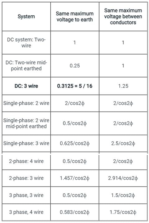
- For the same conductor length, the same amount of power, same losses and same maximum voltage to earth, 3 wire DC system requires a minimum conductor area.
- For transmitting the same amount of power at the same voltage, a three-phase transmission line requires less conductor material than a single-phase line; The three-phase transmission system is so cheaper
- For a given amount of power transmitted through a system, the three-phase system requires conductors with a smaller cross-sectional area; This means a saving of copper and thus the original installation costs are less.
Important Points:
- Below is given the table which shows the ratio of conductor-material in any system compared with that in the corresponding 2-wire DC system.
- Cos φ is the power factor in an AC system.
While designing the distribution to locality of one lac population with medium dense load requirement, we can employ ________.- a)radial system
- b)parallel system
- c)ring main system
- d)any of the mentioned
Correct answer is option 'A'. Can you explain this answer?
While designing the distribution to locality of one lac population with medium dense load requirement, we can employ ________.
a)
radial system
b)
parallel system
c)
ring main system
d)
any of the mentioned
| | Charvi Reddy answered |
Radial System for Distribution to Locality of One Lac Population
Radial system is the best option for designing the distribution to locality of one lac population with medium dense load requirement. Below are the reasons why radial system is the best option:
1. Definition of Radial System
A radial system is an electrical distribution system in which power flows from a single source to the destination point through a series of transformers, feeders, and distribution lines arranged in a radial pattern.
2. Advantages of Radial System
Radial system has several advantages over other distribution systems, such as:
- Simple and easy to design and operate
- Low cost of installation and maintenance
- High reliability and stability
- Easy fault detection and isolation
- Uniform voltage distribution
- Easy expansion and modification
3. Application of Radial System
Radial system is suitable for distribution to a locality of one lac population with medium dense load requirement because:
- It can handle moderate loads efficiently
- It provides a uniform and stable voltage supply to all customers
- It allows easy connection and disconnection of customers without affecting the rest of the system
- It can be easily expanded or modified to meet changing load requirements
Conclusion
In conclusion, radial system is the best option for designing the distribution to locality of one lac population with medium dense load requirement due to its simplicity, reliability, low cost, and efficiency in handling moderate loads.
______ voltages can be available from a 3 wire DC distribution system.- a)2
- b)3
- c)4
- d)1
Correct answer is option 'A'. Can you explain this answer?
______ voltages can be available from a 3 wire DC distribution system.
a)
2
b)
3
c)
4
d)
1
 | Gate Funda answered |
Availability of two voltages in a 3-wire system is preferred over the 2-wire system for d.c. distribution. The principal advantage of this system is that it makes available two voltages at the consumer terminals.
V volts between any outer and neutral and 2V volts between the outers.
V volts between any outer and neutral and 2V volts between the outers.
A DC 2-wire system with mid-point earthed having cross-sectional area of each conductor be ‘a’ and resistance ‘R1’. If the DC tow wire replaces the system, then the ratio of volume of each conductor V1/V2 will be ___________- a)1/4
- b)1/2
- c)4
- d)2
Correct answer is option 'A'. Can you explain this answer?
A DC 2-wire system with mid-point earthed having cross-sectional area of each conductor be ‘a’ and resistance ‘R1’. If the DC tow wire replaces the system, then the ratio of volume of each conductor V1/V2 will be ___________
a)
1/4
b)
1/2
c)
4
d)
2
| | Upasana Joshi answered |
Insufficient information is provided to complete this question. Please provide the missing information.
In an underground cable insulating material is used.- a)Oil impregnated paper
- b)PVC, varnished cambric
- c)Rubber
- d)More than one of the above
Correct answer is option 'D'. Can you explain this answer?
In an underground cable insulating material is used.
a)
Oil impregnated paper
b)
PVC, varnished cambric
c)
Rubber
d)
More than one of the above
 | EduRev GATE answered |
Different types of insulating materials can be used in underground cables depending on the specific requirements and applications.
Common insulating materials used in underground cables include:
Common insulating materials used in underground cables include:
- Oil-impregnated paper: Oil-impregnated paper insulation is a traditional and widely used insulating material for underground cables. The paper is impregnated with a special type of insulating oil to enhance its dielectric properties and provide electrical insulation.
- PVC (Polyvinyl Chloride): PVC insulation is commonly used in underground power cables. It is a thermoplastic material that offers good electrical insulation properties and resistance to moisture and environmental factors.
- Varnished cambric: Varnished cambric is a type of fabric-based insulation that is treated with varnish to enhance its electrical properties. It has been historically used in underground cables but has become less common in modern installations.
- Rubber: Rubber insulation, particularly ethylene propylene rubber (EPR) or cross-linked polyethylene (XLPE), is commonly used in medium and high-voltage underground cables. Rubber offers good electrical insulation properties and is resistant to moisture and environmental factors.
In practice, different types of insulating materials may be used in combination within an underground cable, depending on the specific requirements for voltage rating, environmental conditions, and cable design.
While designing the distribution sub stations by the designer, it is required to use the _______ for the discrete power tapping.- a)distributor
- b)power transformer
- c)distribution transformer
- d)feeder
Correct answer is option 'A'. Can you explain this answer?
While designing the distribution sub stations by the designer, it is required to use the _______ for the discrete power tapping.
a)
distributor
b)
power transformer
c)
distribution transformer
d)
feeder
| | Aaditya Choudhary answered |
Introduction:
In the design of distribution substations, the designer needs to consider various components and equipment to ensure efficient and reliable power distribution. One of the key components in the distribution substation is the discrete power tapping, which is used to distribute power to different loads or consumers.
Explanation:
The correct option for discrete power tapping in distribution substations is distributor. Let's understand why:
1. Distributor:
A distributor is a device used in power distribution systems to distribute power to different loads or consumers. It is responsible for dividing the power from a single source into multiple branches or feeders. The distributor can be considered as a network of switches or circuit breakers that control the flow of power to different loads.
2. Power Transformer:
A power transformer is a device used to transfer electrical energy between two or more electrical circuits through electromagnetic induction. It is primarily used for stepping up or stepping down the voltage levels in the power distribution system. While power transformers play a crucial role in substations, they are not directly involved in discrete power tapping.
3. Distribution Transformer:
A distribution transformer is a type of power transformer specifically designed for the distribution of electrical power to consumers at lower voltage levels. It steps down the voltage from the transmission level to the distribution level and provides power to individual consumers or loads. However, distribution transformers are not directly involved in discrete power tapping.
4. Feeder:
A feeder is a conductor or set of conductors used to carry electrical energy from the substation to individual consumers or loads. It can be considered as a distribution line that connects the substation to various distribution points. While feeders are an essential part of power distribution, they are not used for discrete power tapping.
Conclusion:
In the design of distribution substations, the correct option for the discrete power tapping is a distributor. This device is responsible for distributing power to different loads or consumers by dividing the power from a single source into multiple branches or feeders. Power transformers, distribution transformers, and feeders play different roles in the power distribution system but are not directly involved in discrete power tapping.
A transmission line consists of 9 discs of suspension insulator in each string. What is the operating voltage of the transmission line?- a)11 KV
- b)33 KV
- c)66 KV
- d)132 KV
Correct answer is option 'D'. Can you explain this answer?
A transmission line consists of 9 discs of suspension insulator in each string. What is the operating voltage of the transmission line?
a)
11 KV
b)
33 KV
c)
66 KV
d)
132 KV
| | Raghav Nambiar answered |
Operating Voltage of the Transmission Line
To determine the operating voltage of the transmission line, we need to consider the number of discs of suspension insulator in each string.
Given that there are 9 discs of suspension insulator in each string, we can use this information to calculate the operating voltage.
Insulator Strings
- An insulator string is a set of insulator discs connected in series and used to support the transmission line conductors.
- The insulator discs are designed to withstand high voltages and provide insulation between the conductors and the supporting structure.
Voltage Rating of Insulator Discs
- Each insulator disc has a specific voltage rating, which indicates the maximum voltage it can withstand without breaking down.
- The voltage rating of an insulator disc depends on its design, material, and dimensions.
- Common voltage ratings for insulator discs include 11 kV, 33 kV, 66 kV, 132 kV, etc.
Operating Voltage Calculation
- In a transmission line, the operating voltage is determined by the voltage rating of the insulator discs used in the string.
- Since each string consists of 9 discs of suspension insulator, the operating voltage will be equal to the voltage rating of the insulator disc multiplied by the number of discs in the string.
- Therefore, the operating voltage of the transmission line can be calculated as 9 times the voltage rating of the insulator disc.
Given Data
- Number of discs in each string = 9
Options for Operating Voltage
a) 11 kV
b) 33 kV
c) 66 kV
d) 132 kV
Answer
The correct answer is option d) 132 kV.
Explanation
- Since each string consists of 9 discs of suspension insulator, the operating voltage will be 9 times the voltage rating of the insulator disc.
- None of the given options (11 kV, 33 kV, 66 kV) can be multiplied by 9 to obtain an integer value, except for 132 kV.
- Therefore, the operating voltage of the transmission line is 132 kV.
Sulphur hexafluoride cable is insulated by - a)Impregnated paper
- b)Polyvinyl chloride
- c)High pressure oil
- d)Compressed gas
Correct answer is option 'D'. Can you explain this answer?
Sulphur hexafluoride cable is insulated by
a)
Impregnated paper
b)
Polyvinyl chloride
c)
High pressure oil
d)
Compressed gas
| | Sanchita Choudhary answered |
Insulation of Sulphur Hexafluoride Cable
Insulation of a sulphur hexafluoride cable is achieved through the use of compressed gas. This type of insulation is commonly used in high voltage power cables for various applications.
Compressed Gas Insulation
- Sulphur hexafluoride (SF6) is a colorless, odorless, non-toxic, and non-flammable gas that is commonly used as an electrical insulator in high voltage applications.
- SF6 gas has excellent insulating properties, allowing it to effectively insulate high voltage cables and prevent electrical breakdown.
- The gas is compressed and sealed within the cable to create a protective barrier between the conductors and the external environment.
- Compressed gas insulation is preferred for high voltage applications due to its high dielectric strength and thermal stability.
Advantages of Compressed Gas Insulation
- High dielectric strength: SF6 gas has a high dielectric strength, making it an effective insulator for high voltage applications.
- Thermal stability: SF6 gas is thermally stable, ensuring consistent insulation performance even under varying temperature conditions.
- Compact design: Compressed gas insulation allows for a more compact design of high voltage cables, saving space and reducing installation costs.
- Long service life: SF6 gas insulation is known for its long service life, providing reliable insulation for extended periods.
In conclusion, the insulation of sulphur hexafluoride cable is achieved through compressed gas, specifically SF6 gas, which offers excellent insulation properties for high voltage applications.
Which of the following is NOT a type of DC distributor?- a)Distributor fed at one end
- b)Distributor fed at both ends
- c)Distributor fed at the center
- d)Distributor fed at the horizon
Correct answer is option 'D'. Can you explain this answer?
Which of the following is NOT a type of DC distributor?
a)
Distributor fed at one end
b)
Distributor fed at both ends
c)
Distributor fed at the center
d)
Distributor fed at the horizon
| | Pooja Patel answered |
Types Of DC Distributors:
- DC distributors are usually classified on the basis of the way they are fed by the feeders. Following are the four types of DC distributors.
- Distributor fed at one end
- Distributor fed at both ends
- Distributor fed at the center
- Ring distributor
Distributor Fed At One End:
- In this type, the distributor is connected to the supply at one end and loads are tapped at different points along its length.
- The following figure shows the single-line diagram of a distributor fed at one end. It is worth noting that -
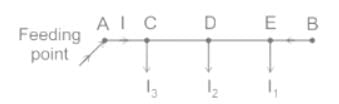
- The current in various sections of the distributor away from the feeding point goes on decreasing.
- From the above figure, the current in section DE is less than the current in section CD and likewise.
- The voltage also goes on to decrease away from the feeding point. In the above figure, the voltage at point E will be minimum.
- In case of a fault in any section of the distributor, the whole distributor will have to be disconnected from the supply. Thus, the continuity of supply is interrupted.
Distributor Fed At Both Ends:
- In this type, the distributor is connected to supply at both ends, and voltages at feeding points may or may not be equal.
- The minimum voltage occurs at some load point which is shifted with the variation of load on different sections of the distributor.

- If a fault occurs at any feeding point, continuity of the supply is ensured from the other feeding point.
- If a fault occurs on any section of the distributor, continuity of the supply is ensured on both sides of the fault with respective feeding points.
- The conductor cross-section area required for a doubly fed distributor is much less than that required for a distributor fed at one end.
Distributor Fed At The Center:
- As the name implies, the distributor is supplied at the center point.
- Voltage drop at the farthest ends is not as large as that would be in a distributor fed at one end.
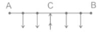
Ring Main DC Distributor:
- In this type, the distributor is in the form of a closed ring and fed at one point.
- This is equivalent to a straight distributor fed at both ends with equal voltages.
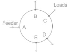
A standard conductor cable is expressed as 3/0.029. The number of strands in the cable is:- a)6
- b)9
- c)3
- d)7
Correct answer is option 'C'. Can you explain this answer?
A standard conductor cable is expressed as 3/0.029. The number of strands in the cable is:
a)
6
b)
9
c)
3
d)
7
| | EduRev GATE answered |
Representation of ACSR strand Conductor:
A standard conductor is represented as A/S/D for ACSR conductor.
Where,
A is the number of aluminum strands.
S is the number of steel strands.
D is the diameter of each strand.
Example: If the ACSR conductor having 7 steel strands surrounded by
25 aluminum conductors with a diameter of 0.05 mm will be specified as
25/7/0.05.
Application:
Given:
Cable is expressed as 3/0.029
This implies the cable consists of 3 strands of 0.029 mm.
Sheath losses can be eliminated by- a)transposing cable along with cross bonding
- b)transposing cables only
- c)cross bonding
- d)none are effective
Correct answer is option 'A'. Can you explain this answer?
Sheath losses can be eliminated by
a)
transposing cable along with cross bonding
b)
transposing cables only
c)
cross bonding
d)
none are effective
| | Jaya Datta answered |
Sheath losses refer to the power losses that occur in the metallic sheath of a cable due to the circulation of eddy currents. These losses can be significant and can lead to a decrease in the overall efficiency of the cable system. However, there are ways to mitigate or eliminate these losses, and one effective method is transposing the cable along with cross bonding.
1. Transposing the cable:
Transposing involves rearranging the positions of the cable conductors within the cable bundle. By interchanging the positions of the conductors, the magnetic fields generated by the current flowing through them are varied. This variation helps to reduce the eddy currents circulating in the metallic sheath and subsequently decreases the sheath losses. Transposing is typically done by switching the positions of the conductors at regular intervals along the length of the cable.
2. Cross bonding:
Cross bonding is another technique used to eliminate sheath losses. It involves connecting the metallic sheath of the cable to the earth at multiple points along its length. By providing multiple earth connections, the circulating currents in the sheath are effectively divided, reducing the overall loss. Cross bonding also helps to equalize the potential difference between different sections of the sheath, minimizing the risk of insulation breakdown.
3. Combined effect of transposing and cross bonding:
Transposing the cable along with cross bonding has a synergistic effect in reducing sheath losses. The transposition helps to vary the magnetic fields, while cross bonding provides multiple earth connections. This combination ensures that the circulating currents in the sheath are minimized, leading to a significant reduction or elimination of sheath losses.
4. Other methods:
While transposing the cable along with cross bonding is the most effective method to eliminate sheath losses, there are other techniques that can be used to mitigate these losses to some extent. These include using magnetic shields, reducing the thickness of the metallic sheath, and using sheath materials with higher resistivity.
In conclusion, sheath losses in cables can be effectively eliminated by transposing the cable along with cross bonding. This combination technique helps to vary the magnetic fields and provides multiple earth connections, minimizing the circulating currents in the metallic sheath and reducing overall power losses.
Which of the following distribution systems is the most economical?- a)Single phase AC system
- b)DC system
- c)Three phase, 4-wire AC system
- d)Three phase, 3-wire AC system
Correct answer is option 'B'. Can you explain this answer?
Which of the following distribution systems is the most economical?
a)
Single phase AC system
b)
DC system
c)
Three phase, 4-wire AC system
d)
Three phase, 3-wire AC system
| | Yashvi Shah answered |
Economical Distribution System
Introduction:
The distribution system is the final stage of power delivery from the power plant to the end-users. The efficiency and cost of the distribution system significantly impact the overall power delivery cost. Therefore, choosing an economical distribution system is crucial for power utilities.
Options:
The given options are:
a) Single phase AC system
b) DC system
c) Three phase, 4-wire AC system
d) Three phase, 3-wire AC system
Explanation:
The most economical distribution system is the one that has low installation cost, low maintenance cost, and high efficiency. Let's evaluate each option based on these criteria.
a) Single phase AC system: It has low installation cost, but it is inefficient, and the maintenance cost is relatively high. Therefore, it is not the most economical option.
b) DC system: It has low installation cost, high efficiency, and low maintenance cost. Moreover, it is suitable for various applications, including renewable energy integration, electric vehicles, and data centers. Therefore, it is the most economical option.
c) Three phase, 4-wire AC system: It has high installation and maintenance costs, and its efficiency is relatively low. Therefore, it is not the most economical option.
d) Three phase, 3-wire AC system: It has a similar installation and maintenance cost as the 4-wire system, and its efficiency is slightly better. However, it is not as efficient as the DC system. Therefore, it is not the most economical option.
Conclusion:
The most economical distribution system is the DC system due to its low installation cost, high efficiency, and low maintenance cost.
Armouring protect cables against- a)earth fault
- b)capacitance leakage
- c)mechanical damage
- d)stray magnetic fields
Correct answer is option 'C'. Can you explain this answer?
Armouring protect cables against
a)
earth fault
b)
capacitance leakage
c)
mechanical damage
d)
stray magnetic fields
| | Sahana Sarkar answered |
Understanding Cable Armouring
Cable armouring is a protective layer designed to enhance the durability and safety of electrical cables. Its primary function is to safeguard the cable from various external threats.
Protection Against Mechanical Damage
- Impact Resistance: Armouring provides a robust layer that can withstand physical impacts, preventing damage from falling objects or heavy machinery.
- Abrasion Resistance: It protects the cable from wear and tear caused by friction against surfaces, ensuring the cable maintains its integrity over time.
- Environmental Protection: Armoured cables are less susceptible to damage from environmental factors, such as rodents or harsh weather conditions.
Why Not Earth Fault, Capacitance Leakage, or Stray Magnetic Fields?
- Earth Fault: This pertains to electrical faults where current leaks to the ground. Armouring does not prevent electrical faults; instead, proper insulation and grounding techniques are used for this purpose.
- Capacitance Leakage: This is related to the undesired flow of current through insulation, often caused by moisture or breakdown of materials. Armouring alone does not address this issue, as it is an electrical insulation concern.
- Stray Magnetic Fields: Armouring does not shield cables from magnetic fields. Instead, specialized materials or configurations are needed to mitigate electromagnetic interference.
Conclusion
In summary, the primary role of cable armouring is to protect against mechanical damage, making option 'C' the correct answer. By providing a strong physical barrier, armouring ensures the longevity and reliability of electrical cables in various environments.
The string efficiency of insulators can be increased by- a)reducing the number of strings
- b)increasing the number of strings
- c)correct grading of insulators of various capacitances
- d)changing the orientation of strings
Correct answer is option 'C'. Can you explain this answer?
The string efficiency of insulators can be increased by
a)
reducing the number of strings
b)
increasing the number of strings
c)
correct grading of insulators of various capacitances
d)
changing the orientation of strings
| | Mansi Choudhury answered |
Understanding Insulator String Efficiency
Insulator strings are crucial in overhead transmission lines, serving to support conductors and prevent electrical leakage to the ground. The efficiency of these insulator strings can significantly impact transmission performance and reliability.
Why Option 'C' is Correct
Correct grading of insulators of various capacitances is the key to enhancing string efficiency. Here’s why:
Conclusion
In summary, while reducing or increasing the number of insulator strings may seem beneficial, it is the correct grading of insulators of varying capacitances that optimally enhances their efficiency and longevity in electrical systems. This approach directly addresses the challenges of voltage distribution and insulator performance.
Insulator strings are crucial in overhead transmission lines, serving to support conductors and prevent electrical leakage to the ground. The efficiency of these insulator strings can significantly impact transmission performance and reliability.
Why Option 'C' is Correct
Correct grading of insulators of various capacitances is the key to enhancing string efficiency. Here’s why:
- Capacitance Balancing: Insulators in a string can have different capacitances due to variations in design or material properties. By grading the insulators properly, you ensure that the voltage across each insulator is distributed evenly, minimizing the risk of failure.
- Reduction of Voltage Stress: Proper grading helps in reducing the maximum voltage stress on each insulator. This is essential for improving the lifespan and reliability of the insulators, as high voltage stress can lead to electrical breakdown.
- Enhanced Performance: When insulators are correctly graded, they can perform effectively under varying environmental conditions. This ensures that the insulators maintain their efficiency over time, contributing to better system performance.
- Mitigation of Corona Losses: Grading can help to minimize corona discharge, which occurs when the electric field around the insulator exceeds a certain level. Properly graded insulators help maintain a lower electric field, thus reducing losses.
Conclusion
In summary, while reducing or increasing the number of insulator strings may seem beneficial, it is the correct grading of insulators of varying capacitances that optimally enhances their efficiency and longevity in electrical systems. This approach directly addresses the challenges of voltage distribution and insulator performance.
The function of steel wire in an ACSR conductor is to- a)compensate for skin effect
- b)take care of surges
- c)provide additional mechanical strength
- d)reduce inductance
Correct answer is option 'C'. Can you explain this answer?
The function of steel wire in an ACSR conductor is to
a)
compensate for skin effect
b)
take care of surges
c)
provide additional mechanical strength
d)
reduce inductance
| | Swati Tiwari answered |
Role of Steel Wire in ACSR Conductors
ACSR (Aluminum Conductor Steel Reinforced) conductors are widely used in overhead power transmission. The inclusion of steel wire in these conductors serves a vital purpose, primarily focusing on mechanical strength.
Mechanical Strength
- The primary function of steel wire in ACSR conductors is to provide additional mechanical strength.
- Aluminum, while having excellent electrical conductivity, is relatively soft and can be susceptible to sagging and breaking under tension.
- The steel core reinforces the conductor, allowing it to withstand physical stress such as wind, ice load, and tension from being strung between poles.
Benefits of Using Steel Wire
- Increased Tensile Strength: The steel core significantly improves the tensile strength of the conductor, enabling it to span longer distances without excessive sag.
- Durability: Steel provides resistance to physical damage, enhancing the overall durability of the conductor in harsh environmental conditions.
- Support for Aluminum: By reinforcing the aluminum, the steel wire allows for a balance between high conductivity and robust structural integrity.
Conclusion
In summary, the steel wire in an ACSR conductor is crucial for maintaining the mechanical strength necessary for reliable and efficient overhead power transmission. Its role in reinforcing the conductor ensures that it can endure the various stresses encountered in real-world applications, making it an essential component of this type of electrical conductor.
Which of the following is NOT a disadvantage of the direct laying method?- a)The maintenance cost is very high.
- b)Heat can be dissipated easily
- c)It cannot be used in congested areas.
- d)Localization of the fault is difficult.
Correct answer is option 'B'. Can you explain this answer?
Which of the following is NOT a disadvantage of the direct laying method?
a)
The maintenance cost is very high.
b)
Heat can be dissipated easily
c)
It cannot be used in congested areas.
d)
Localization of the fault is difficult.
 | Crack Gate answered |
Direct Laying Of Underground Cables
The cables to be laid using this method must have a serving of bituminized paper and hessian tape so as to provide protection against corrosion and electrolysis.
The direct laying procedure is as follows:
- A trench of about 1.5 meters deep and 45 cm wide is dug.
- Then the trench is covered with a 10 cm thick layer of fine sand.
- The cable is laid over the sand bed. The sand bed protects the cable from moisture from the ground.
- Then the laid cable is again covered with a layer of sand about 10 cm thick.
- When multiple cables are to be laid in the same trench, a horizontal or verticle spacing of about 30 cm is provided to reduce the effect of mutual heating. Spacing between the cables also ensures a fault occurring on one cable does not damage the adjacent cable.
- The trench is then covered with bricks and soil to protect the cable from mechanical injury.
Advantages
- Simple and cheap method.
- The heat generated in cables is easily dissipated in the ground.
Disadvantages
- Alterations in the cable network are not easy.
- Maintenance cost is higher.
- Identifying the location of a fault is difficult.
- This method can not be used in congested areas such as metro cities where excavation is too expensive.
If r is the radius of the conductor and R the radius of the sheath of the cable, the cable operates stably from the view point of dielectric strength if:- a)

- b)

- c)

- d)

Correct answer is option 'B'. Can you explain this answer?
If r is the radius of the conductor and R the radius of the sheath of the cable, the cable operates stably from the view point of dielectric strength if:
a)
b)
c)
d)
| | Ishani Iyer answered |
The cable operates stably from the view point of dielectric strength if, 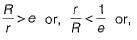

For high voltage transmission lines, conductors are suspended from towers so as to- a)increase clearance from ground
- b)reduce wind and snow effect
- c)take care of increase in length
- d)reduce clearance from ground
Correct answer is option 'A'. Can you explain this answer?
For high voltage transmission lines, conductors are suspended from towers so as to
a)
increase clearance from ground
b)
reduce wind and snow effect
c)
take care of increase in length
d)
reduce clearance from ground
| | Tanishq Majumdar answered |
Introduction:
High voltage transmission lines are used to transmit large amounts of electrical power over long distances. These lines are supported by towers, and the conductors are suspended from these towers. The purpose of this arrangement is to ensure the efficient and safe transmission of electricity.
Explanation:
The correct answer to the given question is option 'A', which states that conductors are suspended from towers to increase clearance from the ground. Let's understand why this is the correct answer.
1. Safety:
The primary reason for suspending the conductors from towers is to ensure safety. By increasing the clearance from the ground, the risk of accidental contact between the conductors and the ground or other objects is minimized. This is particularly important for high voltage transmission lines, as they carry extremely high voltages that can be hazardous if they come into contact with people or objects on the ground.
2. Clearance from Obstacles:
By suspending the conductors from towers, a sufficient clearance is maintained from various obstacles such as buildings, trees, and vehicles. This prevents the conductors from coming into contact with these objects, reducing the risk of damage to the conductors and the objects themselves. It also helps to prevent power outages and interruptions in the transmission of electricity.
3. Snow and Ice:
In regions with cold climates, snow and ice can accumulate on the conductors. By suspending the conductors from towers, the distance between the conductors and the ground is increased, reducing the likelihood of snow and ice buildup. This helps to maintain the reliability and efficiency of the transmission lines, as excessive snow and ice can cause electrical faults and interruptions.
4. Wind Effects:
High voltage transmission lines are exposed to strong winds, especially in open areas. By suspending the conductors from towers, the effect of wind on the conductors is minimized. The elevated position of the conductors reduces the wind load, preventing excessive movement and reducing the stress on the conductors and the towers. This helps to maintain the structural integrity of the transmission line system.
Conclusion:
In conclusion, conductors are suspended from towers in high voltage transmission lines to increase clearance from the ground. This arrangement ensures the safety of people and objects on the ground, maintains a sufficient distance from obstacles, reduces the effects of snow and ice buildup, and minimizes the impact of wind on the conductors. Overall, it helps to ensure the efficient and reliable transmission of electricity over long distances.
Match List-l (Type of Cables) with List-ll (Operatng Voltages) and select the correct answer using the code given below the lists:
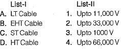
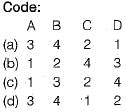
- a)D
- b)B
- c)C
- d)A
Correct answer is option 'D'. Can you explain this answer?
Match List-l (Type of Cables) with List-ll (Operatng Voltages) and select the correct answer using the code given below the lists:
a)
D
b)
B
c)
C
d)
A
 | Engineers Adda answered |
(A)
LT (Low Tension) cables are used for voltages up to 1,000 V, so A → 3.
HT (High Tension) cables are typically used for distribution at voltages up to 11,000 V, so D → 1.
ST (Sub-transmission) cables are used for voltages around 33,000 V, so C → 2.
EHT (Extra-High Tension) cables are used for higher transmission voltages such as up to 66,000 V, so B → 4.
Therefore the correct matching is A → 3, B → 4, C → 2, D → 1, which corresponds to option (A).
Chapter doubts & questions for Distribution Systems, Cables & Insulators - Power Systems 2026 is part of Electrical Engineering (EE) exam preparation. The chapters have been prepared according to the Electrical Engineering (EE) exam syllabus. The Chapter doubts & questions, notes, tests & MCQs are made for Electrical Engineering (EE) 2026 Exam. Find important definitions, questions, notes, meanings, examples, exercises, MCQs and online tests here.
Chapter doubts & questions of Distribution Systems, Cables & Insulators - Power Systems in English & Hindi are available as part of Electrical Engineering (EE) exam. Download more important topics, notes, lectures and mock test series for Electrical Engineering (EE) Exam by signing up for free.
Power Systems21 videos|112 docs|45 tests |