


All Exams > Electrical Engineering (EE) > Electrical Engineering SSC JE (Technical) > All Questions
All questions of Generation, Transmission and Distribution for Electrical Engineering (EE) Exam
The main advantage of AC transmission system over DC transmission system is- a)easy transformation
- b)less losses in transmission over long distances
- c)less insulation problems
- d)less problem of instability
Correct answer is option 'B'. Can you explain this answer?
The main advantage of AC transmission system over DC transmission system is
a)
easy transformation
b)
less losses in transmission over long distances
c)
less insulation problems
d)
less problem of instability
 | Shivam Sharma answered |
The Advantages of DC. More efficient: Over long distances, DC transmission can move more power with less electrical losses than an equivalent AC transmission line. Lower Cost: Higher efficiency means a lower transmission cost, helping renewable energy compete against other power sources.

The fusing factor of HRC fuse is- a)1.8
- b)1.5
- c)1.1
- d)1.4
Correct answer is option 'C'. Can you explain this answer?
The fusing factor of HRC fuse is
a)
1.8
b)
1.5
c)
1.1
d)
1.4
| | Aditya Deshmukh answered |
This is the ratio of minimum fusing current and current rating of fuse. Therefore, fusing factor = Minimum fusing current or current rating of the fuse. The value of fusing factor is always more than 1.
In an underground cable, insulating material is useda) rubberb) PVCc) any of the aboved) none of the aboveCorrect answer is option 'C'. Can you explain this answer?
| | Om Desai answered |
The principal insulating materials used in cables are rubber, vulcanised India rubber,impregnated paper, varnished cambric and polyvinyl chloride.
Which of the following statements is incorrect ?- a)As the temperature rises, the tension in the transmission line decreases
- b)As temperature rises the sag in transmission lines reduces
- c)Tension and sag in transmission lines are complementary to each other.
- d)None of the above
Correct answer is option 'B'. Can you explain this answer?
Which of the following statements is incorrect ?
a)
As the temperature rises, the tension in the transmission line decreases
b)
As temperature rises the sag in transmission lines reduces
c)
Tension and sag in transmission lines are complementary to each other.
d)
None of the above
| | Aditya Deshmukh answered |
Sag is defined as the different in level between points of supports and the lowest point on the conductor. Here AOB is the transmission line conductor. Two supports are at point A and at point B. AB is the horizontal line and from this horizontal line to point O, S is the sag when measured vertically.
Temperature has different effects — while increasing
- Mechanically there will be huge Sag due to thermal expansion - ground clearance will be compromised.
- Resistance of conductor will increase also as materiel property — making more I^2*R losses apart from losses due to increased current.
- The UTS will start reducing as well as due to expansion tension will reduce in conductor. In case the tension doesn't decrease much but Ultimate Tensile Strength decreased more it will snap
Series capacitors on transmission lines are of little used when- a)the load VAR requirement is small
- b)the load VAR requirement is large
- c)the load VAR requirement is fluctuating
- d)Series capacitors are never used on transmission lines
Correct answer is option 'A'. Can you explain this answer?
Series capacitors on transmission lines are of little used when
a)
the load VAR requirement is small
b)
the load VAR requirement is large
c)
the load VAR requirement is fluctuating
d)
Series capacitors are never used on transmission lines
 | Mrinalini Sen answered |
Series compensation is the method of improving the system voltage by connecting a capacitor in series with the transmission line. In other words, in series compensation, reactive power is inserted in series with the transmission line for improving the impedance of the system. It improves the power transfer capability of the line. It is mostly used in extra and ultra high voltage line.
For the transmission of same power- a)DC line requires more copper than an AC line
- b)AC line requires more copper than a DC line
- c)Both AC as well as DC line need same copper
- d)None of the above
Correct answer is option 'B'. Can you explain this answer?
For the transmission of same power
a)
DC line requires more copper than an AC line
b)
AC line requires more copper than a DC line
c)
Both AC as well as DC line need same copper
d)
None of the above
| | Lavanya Menon answered |
Explanation:
- AC lines require more copper than DC lines for the transmission of the same power. This is because AC lines experience skin effect, which causes the current to concentrate near the surface of the conductor, leading to higher resistance and more power loss. To compensate for this, AC lines need to have larger conductors with more copper.
- DC lines, on the other hand, do not experience skin effect and have lower resistance, resulting in less power loss. Therefore, DC lines require less copper compared to AC lines for transmitting the same amount of power.
For the transmission of same power AC line requires more copper than a DC line
The permissible variation in supply frequency is- a)+ 1%
- b)+ 2%
- c)+ 3%
- d)+ 5%
Correct answer is option 'D'. Can you explain this answer?
The permissible variation in supply frequency is
a)
+ 1%
b)
+ 2%
c)
+ 3%
d)
+ 5%
| | Sanya Agarwal answered |
According to
CENTRAL ELECTRICITY REGULATORY COMMISSION OF INDIA
CENTRAL ELECTRICITY REGULATORY COMMISSION OF INDIA
Ideal Range of frequency variation
f = 50 ± 1%
49.5 to 50.5 Hz
Practical permissible Range of frequency variation
f = 50 ± 3%
48.5 to 51.5 Hz
The grid frequency should be maintained at 48.6 Hz. and above at all times.
Two pin sockets should not be used in domestic wiring unless the appliance to be connected is- a)double earthed
- b)double insulated
- c)controlled by ELCB
- d)controlled by MCB
Correct answer is option 'B'. Can you explain this answer?
Two pin sockets should not be used in domestic wiring unless the appliance to be connected is
a)
double earthed
b)
double insulated
c)
controlled by ELCB
d)
controlled by MCB
 | Engineers Adda answered |
Correct Answer :- b
Explanation : Two pin sockets should not be used in domestic wiring unless the appliance to be connected is double insulated.
Standard domestic ac supply voltage in India is- a)220 V
- b)240 V
- c)230 V
- d)None of these
Correct answer is option 'C'. Can you explain this answer?
Standard domestic ac supply voltage in India is
a)
220 V
b)
240 V
c)
230 V
d)
None of these
| | Yashvi Shah answered |
In India the standard voltage is 230 V and the frequency is 50 Hz.
A fault occurring at the terminals of an unloaded synchronous generator operating at its rate voltage has resulted in the following values of currents and voltages Ia0 = j2.37 pu, Ia1 = –j3.05 pu, Ia2 = j0.68 pu,Va0 = Va1 = Va2 = 0.237 pu- a)L-L fault.
- b)L-G fault.
- c)L-L-G fault.
- d)L-L-L fault.
Correct answer is option 'D'. Can you explain this answer?
A fault occurring at the terminals of an unloaded synchronous generator operating at its rate voltage has resulted in the following values of currents and voltages Ia0 = j2.37 pu, Ia1 = –j3.05 pu, Ia2 = j0.68 pu,Va0 = Va1 = Va2 = 0.237 pu
a)
L-L fault.
b)
L-G fault.
c)
L-L-G fault.
d)
L-L-L fault.
| | Srestha Gupta answered |
0 pu, Vt0 = 1 pu, and Vt1 = -j0.8 pu.
This fault is most likely a single line-to-ground fault, which has caused the phase a current to be displaced by 90 degrees (i.e., Ia0 is purely imaginary) and the phase a voltage to be reduced by a significant amount (i.e., Vt1 is negative and has a large magnitude).
To determine the fault location and type, additional information such as the system topology and impedance values would be needed. However, based on the given information, it is not possible to determine these parameters.
Energy meter, for connecting, has ––––––– terminals.- a)2
- b)4
- c)6
- d)8
Correct answer is option 'B'. Can you explain this answer?
Energy meter, for connecting, has ––––––– terminals.
a)
2
b)
4
c)
6
d)
8
| | Tanvi Shah answered |
Correct Answer :- b
Explanation : An energy meter usually has four terminals. A pair of terminals for the current coil and another pair for the Voltage coil (a.k.a pressure coil). As their name suggests, current coil is in series with the line and or produces magnetic field according to the current flow.
Whereas Voltage coil is in parallel with the Load and it produces magnetic field according to the voltage drop across the Load.
These two fields combine to produce a torque which rotates the aluminum disc on a conventional Energy meter.
Can you explain the answer of this question below:If the length of a cable is double , its capacitance
- A:
becomes half
- B:
becomes one fourth
- C:
remains unaltered
- D:
becomes double
The answer is d.
If the length of a cable is double , its capacitance
becomes half
becomes one fourth
remains unaltered
becomes double
 | Swara Dasgupta answered |
1. Capacitance exists between two things with different electric charge and a dielectric in between.
2. The transmission line and the earth below it, have a charge difference and the air between them is dielectric. This constitutes a capacitance.
3. The longer the cable, the more part of it runs parallel to the earth and hence, more capacitance between them since the length of the cable and the capacitance of the cable are directly proportional to each other.
Which of the following is not a standard transmission voltage?- a)132 kV
- b)222 kV
- c)400 kV
- d)750 kV
Correct answer is option 'B'. Can you explain this answer?
Which of the following is not a standard transmission voltage?
a)
132 kV
b)
222 kV
c)
400 kV
d)
750 kV
| | Aditya Deshmukh answered |
STANDARD TRANSMISSION VOLTAGES
Voltages adopted for transmission of bulk power have to conform to standard specifications formulated in all countries and internationally. They are necessary in view of import, export, and domestic manufacture and use. The following voltage levels are recognized in India as per IS-2026 for line-to-line voltages of 132 kV and higher.
Nominal System
Voltage kV 132 220 275 345 400 500 750
Maximum Operating
Voltage, kV 145 245 300 362 420 525 765
Plug setting of an electromagnetic relay can be altered by varying- a)number of ampere turns
- b)air gap of magnetic path.
- c)adjustable back stop
- d)none of these
Correct answer is option 'A'. Can you explain this answer?
Plug setting of an electromagnetic relay can be altered by varying
a)
number of ampere turns
b)
air gap of magnetic path.
c)
adjustable back stop
d)
none of these
| | Disha Das answered |
Explanation:
The plug setting of an electromagnetic relay can be altered by varying the number of ampere turns on the relay coil. The plug setting is the current level at which the relay operates. It is important to set the plug setting correctly to ensure proper protection of the system and equipment. The following points explain how the plug setting can be altered by varying the number of ampere turns on the relay coil:
Ampere Turns:
Ampere turns is a measure of the magnetic field strength produced by the relay coil. It is the product of the number of turns in the coil and the current flowing through it. The magnetic field produced by the coil is used to attract or repel the armature of the relay, which in turn operates the contacts.
Plug Setting:
The plug setting is the current level at which the relay operates. It is typically set using a plug or a screw adjustment on the relay. The plug setting is important because it determines the level of current at which the relay will operate and trip the circuit breaker.
Altering Plug Setting:
The plug setting of a relay can be altered by varying the number of ampere turns on the relay coil. This can be done by either increasing or decreasing the number of turns in the coil or by varying the current flowing through it. By altering the ampere turns, the magnetic field strength produced by the coil is changed, which affects the operation of the relay.
Conclusion:
Therefore, the correct answer is option 'A', that the plug setting of an electromagnetic relay can be altered by varying the number of ampere turns.
If a combination of HRC fuse and a circuit breaker is used, the circuit breaker operates for- a)short-circuit current.
- b)the combination is newer employed in practice
- c)under all abnormal currents.
- d)low overload currents.
Correct answer is option 'D'. Can you explain this answer?
If a combination of HRC fuse and a circuit breaker is used, the circuit breaker operates for
a)
short-circuit current.
b)
the combination is newer employed in practice
c)
under all abnormal currents.
d)
low overload currents.
| | Yashvi Shah answered |
Explanation:
The combination of an HRC fuse and a circuit breaker is a common practice in electrical systems. The HRC fuse is used to protect against short-circuit currents, while the circuit breaker is used to protect against overloads.
However, when both devices are used together, the circuit breaker should be set to operate at a low overload current. This is because the HRC fuse will typically clear any short-circuit current before the circuit breaker has a chance to trip.
Therefore, the circuit breaker in this combination is primarily used to protect against low overload currents that may not be cleared by the HRC fuse alone.
In summary, the correct answer is option 'D' - the circuit breaker operates for low overload currents.
The zero-sequence current of a generator for line-to ground fault is j2.4 pu. Then the current through the neutral during the fault is- a)j2.4 pu
- b)j0.8 pu
- c)j7.8 pu
- d)j0.24 pu
Correct answer is option 'C'. Can you explain this answer?
The zero-sequence current of a generator for line-to ground fault is j2.4 pu. Then the current through the neutral during the fault is
a)
j2.4 pu
b)
j0.8 pu
c)
j7.8 pu
d)
j0.24 pu
| | Mrinalini Sen answered |
Ia0 = (1/3)Ia = Ia = In = 3Ia0
= 3 x j2.4 = j7.2 pu
A 11 kV underground cable is layed at a depth of- a)0.1 m
- b)0.5 m
- c)0.9 m
- d)1.5 m
Correct answer is option 'C'. Can you explain this answer?
A 11 kV underground cable is layed at a depth of
a)
0.1 m
b)
0.5 m
c)
0.9 m
d)
1.5 m
| | Rajeev Menon answered |
Depth — The desired minimum depth of laying from ground surface to the top of cable is as follows:
1. High voltage cables, 3.3 kV to 11 kV rating = 0.9 m
2. High voltage cables, 22 kV, 33 kV rating= 1.05 m
3. Low voltage and control cables = 0.75 m
4. Cables at road crossings = 1.00 m
The maximum demand of a consumer is 2 kW and the corresponding daily energy consumption is 30 unit. What is the corresponding load factor ?- a)25%
- b)50%
- c)62.5 %
- d)75%
Correct answer is option 'C'. Can you explain this answer?
The maximum demand of a consumer is 2 kW and the corresponding daily energy consumption is 30 unit. What is the corresponding load factor ?
a)
25%
b)
50%
c)
62.5 %
d)
75%
| | Prisha Sen answered |
Calculation of Load Factor
Load factor is the ratio of average load to the maximum demand during a given period of time. It is a measure of the efficiency of energy utilization. The formula for load factor is:
Load factor = Average load / Maximum demand
Given data:
Maximum demand = 2 kW
Daily energy consumption = 30 units
We can calculate the average load as follows:
Average load = Daily energy consumption / 24 hours
= 30 units / 24 hours
= 1.25 kW
Therefore, the load factor is:
Load factor = Average load / Maximum demand
= 1.25 kW / 2 kW
= 0.625 or 62.5 %
Therefore, the correct option is C.
If the positive,-negative-and zero-sequence reactances of an element of a power system are 0.3, 0.3 and 0.8 pu respectively, then the element would be a- a)synchronous generator.
- b)synchronous motor.
- c)static load.
- d)transmission line.
Correct answer is option 'D'. Can you explain this answer?
If the positive,-negative-and zero-sequence reactances of an element of a power system are 0.3, 0.3 and 0.8 pu respectively, then the element would be a
a)
synchronous generator.
b)
synchronous motor.
c)
static load.
d)
transmission line.
| | Ameya Nambiar answered |
Given information:
- Positive sequence reactance = 0.3 pu
- Negative sequence reactance = 0.3 pu
- Zero sequence reactance = 0.8 pu
Explanation:
To determine the type of element, we need to understand the behavior of each sequence reactance for different elements in a power system.
1. Synchronous generator:
A synchronous generator has a large positive sequence reactance and a small negative sequence reactance. The zero sequence reactance is usually very small or zero. Therefore, the given values of reactances do not match with those of a synchronous generator.
2. Synchronous motor:
A synchronous motor has a large negative sequence reactance and a small positive sequence reactance. The zero sequence reactance is usually very small or zero. Therefore, the given values of reactances do not match with those of a synchronous motor.
3. Static load:
A static load has equal positive, negative, and zero sequence impedances. Therefore, the given values of reactances do not match with those of a static load.
4. Transmission line:
A transmission line has equal positive and negative sequence impedances and a larger zero sequence impedance. Therefore, the given values of reactances match with those of a transmission line.
Conclusion:
From the above explanation, we can conclude that the given element is a transmission line.
Time delay relay is used in which relay type- a)magnetic relay
- b)thermal relay
- c)reed relay
- d)latching relay
Correct answer is option 'B'. Can you explain this answer?
Time delay relay is used in which relay type
a)
magnetic relay
b)
thermal relay
c)
reed relay
d)
latching relay
 | Bijoy Kapoor answered |
A thermal relay works depending upon the above mentioned property of metals. The basic working principle of thermal relay is that, when a bimetallic strip is heated up by a heating coil carrying over current of the system, it bends and makes normally open contacts.
Construction of Thermal Relay
The construction of thermal relay is quite simple. As shown in the figure above the bimetallic strip has two metals – metal A and metal B. Metal A has lower coefficient of expansion and metal B has higher coefficient of expansion.
Compared to Gauss-seidel method, Newton- Raphson method takes- a)Less number of iterations and more time per iteration
- b)Less numbers of iterations and less time per iteration
- c)More number of iterations and more time per iteration
- d)More number of iterations and less time per iteration
Correct answer is option 'A'. Can you explain this answer?
Compared to Gauss-seidel method, Newton- Raphson method takes
a)
Less number of iterations and more time per iteration
b)
Less numbers of iterations and less time per iteration
c)
More number of iterations and more time per iteration
d)
More number of iterations and less time per iteration
| | Alok Khanna answered |
Newton-Raphson method and Gauss-Seidel method are two commonly used iterative methods for solving nonlinear equations. In this question, we are asked to compare these two methods in terms of the number of iterations and time per iteration.
Newton-Raphson Method:
• The Newton-Raphson method is an iterative method used to find the roots of nonlinear equations.
• It requires the first derivative of the function to be calculated.
• In each iteration, it updates the guess value using the formula Xn+1=Xn-f(Xn)/f'(Xn)
• It converges faster than other iterative methods.
Gauss-Seidel Method:
• The Gauss-Seidel method is an iterative method used to solve a system of linear equations.
• It updates the guess value for each variable in each iteration.
• It converges slower than Newton-Raphson method.
Comparison:
• The Newton-Raphson method requires the calculation of the first derivative, which is an additional calculation compared to the Gauss-Seidel method.
• However, the Newton-Raphson method converges faster than the Gauss-Seidel method. So, it requires less number of iterations to converge.
• On the other hand, the Gauss-Seidel method requires fewer calculations per iteration compared to the Newton-Raphson method. Hence, it takes less time per iteration.
• Therefore, the correct answer is option 'A', i.e., Newton-Raphson method takes less number of iterations and more time per iteration compared to the Gauss-Seidel method.
What is the nominal pH value of water that is to be maintained in a steam raising thermal power station ?- a)0.0
- b)7.0
- c)8.5
- d)14.3
Correct answer is option 'C'. Can you explain this answer?
What is the nominal pH value of water that is to be maintained in a steam raising thermal power station ?
a)
0.0
b)
7.0
c)
8.5
d)
14.3
 | Anirban Khanna answered |
Depends on the Material of construction being used for the various power plant equipment. Typically a super critical power plant uses Low alloy steels for it's boilers and Stainless steel for other feed regenerative equipment. Turbine blades are generally made of exotic material. Considering all these the typical pH value of the steam cycle water is maintained between 8.5 to 9.5.
To detect inter-phase fault of three phase line, the number of relays needed will be- a)One
- b)Two
- c)Three
- d)Four
Correct answer is option 'B'. Can you explain this answer?
To detect inter-phase fault of three phase line, the number of relays needed will be
a)
One
b)
Two
c)
Three
d)
Four
| | Anirban Khanna answered |
Protective relays are used to detect the interphase faults . Phase to phase faults in a electrical machine. Inter-phase faults leads to generate huge current in the system which can damage the machine. Phase to phase short circuit fault makes the path voltage zero and generates short circuit current. This huge current can burn the windings by producing more heat . This huge heat can not be cooled down by means for hydrogen cooling or oil cooling . So if we want to restrict this short circuit current we have to detect the fault at first and then break the circuit by the corresponding circuit breaker attached with the relay..Over current relay can be used to protect the system from this huge current. Instantenous type over current relay is used to detect the instantenous rise of circuit current beyond the predetermined value..During over current takes place in the system relay trips and makes the circuit breaker open attached with the corresponding Over current relay .
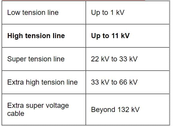
High tension cables can be used for transmission of voltage upto- a)66 kv
- b)22 kv
- c)33 kv
- d)11 kv
Correct answer is option 'D'. Can you explain this answer?
High tension cables can be used for transmission of voltage upto
a)
66 kv
b)
22 kv
c)
33 kv
d)
11 kv
| | Shivam Sharma answered |
The type of cable to be used at a particular location is determined by the mechanical considerations and the voltage at which it is required to operate. According to voltage these are classified as low-voltage cables for operating voltage up to 1kv, high-voltage cables for operating voltage up to 11KV, super tension cables for operating voltage up to 33 KV, extra high tension cables for operating voltage up to 66KV and extra super voltage power cables for operating voltage beyond 132KV.
If the fault current is 2 kA, the relay setting is 50% and the C.T. ratio is 400/5, then the plug setting multiplier of a relay will be- a)5
- b)7
- c)8
- d)10
Correct answer is option 'D'. Can you explain this answer?
If the fault current is 2 kA, the relay setting is 50% and the C.T. ratio is 400/5, then the plug setting multiplier of a relay will be
a)
5
b)
7
c)
8
d)
10
| | Pallavi Nair answered |
Calculation of Plug Setting Multiplier
Given:
- Fault current (Isc) = 2 kA
- Relay setting = 50%
- CT ratio = 400/5
We know that the plug setting multiplier (PSM) is given by:
PSM = (Isc × Relay setting × CT ratio) / (Pick-up current of the relay)
Pick-up current of the relay = Relay setting × CT primary current
Therefore, Pick-up current of the relay = 50% × 400 A = 200 A
Substituting the given values in the PSM equation, we get:
PSM = (2 kA × 50% × 400/5) / 200 A
PSM = 10
Hence, the plug setting multiplier of the relay will be 10.
Conclusion
The plug setting multiplier of a relay can be calculated using the formula PSM = (Isc × Relay setting × CT ratio) / (Pick-up current of the relay). In this case, the PSM is found to be 10.
Fuse material must have- a)high melting point and high specific resistance
- b)low melting point and high specific resistance
- c)low melting point and low specific resistance
- d)high melting point and low specific resistance
Correct answer is option 'C'. Can you explain this answer?
Fuse material must have
a)
high melting point and high specific resistance
b)
low melting point and high specific resistance
c)
low melting point and low specific resistance
d)
high melting point and low specific resistance
| | Snehal Rane answered |
Fuse Material Properties
Fuse material is a crucial component for the safety and protection of electrical circuits. It needs to have specific properties to perform its function effectively.
Low Melting Point
The fuse material should have a low melting point to ensure that it melts quickly and opens the circuit when an excessive current flows through it. If the melting point is too high, the fuse will not open the circuit promptly, and the current may damage the equipment or cause a fire.
Low Specific Resistance
The fuse material should have low specific resistance to minimize the voltage drop across it when the current flows through it. If the specific resistance is too high, the voltage drop across the fuse will be significant, and it may cause malfunctioning of the equipment.
Conclusion
Thus, the correct option is 'C' - low melting point and low specific resistance. The low melting point ensures the fuse opens the circuit quickly, and the low specific resistance reduces the voltage drop across the fuse.
The sag in a transmission line conductors depends upon
- a),Conductor material
- b)Height of the tower
- c)The tension in conductors
- d)(a), (b) and (c)
Correct answer is option 'D'. Can you explain this answer?
The sag in a transmission line conductors depends upon
a)
,Conductor material
b)
Height of the tower
c)
The tension in conductors
d)
(a), (b) and (c)
| | Avantika Kaur answered |
The sag in a transmission line conductors depends on several factors. These factors are discussed below:
Conductor Material:
The material used in the construction of the conductor affects its sag. Conductors made up of different materials have different thermal expansion coefficients, which result in varying amounts of sag. For instance, aluminum conductors have higher thermal expansion coefficients than steel conductors. Therefore, they tend to sag more when exposed to high temperatures.
Height of the Tower:
The height of the tower affects the sag of the conductor as it determines the span between two towers. The longer the span, the more the conductor sags. Therefore, taller towers can help reduce sag as they increase the height of the conductor above the ground.
The Tension in Conductors:
The tension in the conductor affects the sag as it determines the force acting on the conductor. The higher the tension, the less the sag. Therefore, increasing the tension in the conductor can help reduce sag.
Conclusion:
In conclusion, the sag in a transmission line conductor depends on several factors such as the conductor material, height of the tower, and the tension in conductors. A combination of these factors can be used to reduce sag and maintain the stability of the transmission line.
The material used in liquid fuses is- a)SF6
- b)distilled water.
- c)carbon tetra chloride.
- d)transformer oil.
Correct answer is option 'C'. Can you explain this answer?
The material used in liquid fuses is
a)
SF6
b)
distilled water.
c)
carbon tetra chloride.
d)
transformer oil.
| | Shivam Sharma answered |
Liquid type fuses
These fuses are filled with carbon tetrachloride and they have wide range of application in high voltage systems. They may be used in circuits with 100A rated current in 132kV system. The breaking capacity is of the order of 6100A. It consists of a glass tube filled with carbon tetrachloride solution with both ends sealed with brass caps. The fuse wire is sealed at one end of the tube and the other end is held strongly by a phosphor bronze spiral spring fixed at one end of the glass tube.
A relay used on short transmission lines is- a)Reactance relay
- b)mho'n relay
- c)impedance relay
- d)None of these
Correct answer is option 'A'. Can you explain this answer?
A relay used on short transmission lines is
a)
Reactance relay
b)
mho'n relay
c)
impedance relay
d)
None of these
| | Mrinalini Sen answered |
Reactance relay used for the small transmission line. mho relay used in the long transmission line. impedance is non-directional and used in medium transmission lines. reactance relay is non directional and used in short transmission lines.
A distribution transformer is normally a transformer with primary and secondary winding sconnected in- a) Star-star
- b) Star-delta
- c) Delta-delta
- d) Delta-star
Correct answer is option 'D'. Can you explain this answer?
A distribution transformer is normally a transformer with primary and secondary winding sconnected in
a)
Star-starb)
Star-deltac)
Delta-deltad)
Delta-star  | Rahul Chatterjee answered |
That is the input and output voltages for the windings are the same. However, if the 3-phase transformer is connected in star–delta, ( Yd ) each star-connected primary winding will receive the phase voltage, VP of the supply, which is equal to 1/√3 x VL.
A thermal generating station has an installedM capacity of 15 MW and supplies a daily load of10 MW for 12 hours and 5 MW of remaining 12 hours. The plant capacity factor for this station is- a)1
- b)0.75
- c)0.67
- d)0.5
Correct answer is option 'D'. Can you explain this answer?
A thermal generating station has an installedM capacity of 15 MW and supplies a daily load of10 MW for 12 hours and 5 MW of remaining 12 hours. The plant capacity factor for this station is
a)
1
b)
0.75
c)
0.67
d)
0.5
| | Tanvi Shah answered |
Plant capacity factor =
average energy produced/maximum possible energy based on installed capacity
= 10 x12 + 5 x 12 / 24 x 15 = 0.5
Zero-sequence fault current is absent when fault is- a)single-line-to ground fault.
- b)line-to-line ground fault.
- c)double-line-to ground fault.
- d)line-to-line
Correct answer is option 'D'. Can you explain this answer?
Zero-sequence fault current is absent when fault is
a)
single-line-to ground fault.
b)
line-to-line ground fault.
c)
double-line-to ground fault.
d)
line-to-line
| | Lavanya Menon answered |
-Zero-sequence fault current is a current or voltage unbalance between phases in magnitude or phase angle gives rise to negative and zero-sequence components.
-The negative sequence component has a rotation opposite that of the power system.
-The zero-sequence component represents an unbalance that causes current flow in the neutral.
-Zero-sequence fault current is absent when fault is line-to-line.
For rural electrification in a country like India with complex network, the circuit breaker preferred is ....... one.- a)minimum oil
- b)air-blast
- c)SF6
- d)air-break
Correct answer is option 'C'. Can you explain this answer?
For rural electrification in a country like India with complex network, the circuit breaker preferred is ....... one.
a)
minimum oil
b)
air-blast
c)
SF6
d)
air-break
| | Sakshi Roy answered |
The preferred circuit breaker for rural electrification in a country like India with a complex network is SF6.
Advantages of SF6 circuit breaker:
1. Excellent insulating properties: SF6 gas has excellent electrical insulation properties, making it ideal for use in high-voltage switchgear.
2. High dielectric strength: SF6 gas has a high dielectric strength, which means it can withstand high voltages without breaking down.
3. Low maintenance: SF6 circuit breakers require very little maintenance, making them ideal for use in rural areas where maintenance facilities may not be readily available.
4. Compact design: SF6 circuit breakers have a compact design, which means they take up less space compared to other types of circuit breakers.
5. Long lifespan: SF6 circuit breakers have a long lifespan, which means they can be used for many years without needing to be replaced.
6. Environmentally friendly: SF6 gas is a greenhouse gas, but it has a very low impact on the environment due to its low atmospheric lifetime.
Conclusion:
In conclusion, SF6 circuit breakers are the preferred choice for rural electrification in a country like India due to their excellent insulating properties, high dielectric strength, low maintenance, compact design, long lifespan, and environmental friendliness.

Porcelain insulators are glazed because- a)to prevent absorption of gases and water vapour
- b)good appearance
- c)increases mechanical strength
- d)safe from sunlight
Correct answer is option 'A'. Can you explain this answer?
Porcelain insulators are glazed because
a)
to prevent absorption of gases and water vapour
b)
good appearance
c)
increases mechanical strength
d)
safe from sunlight
| | Anirban Khanna answered |
Porcelain in most commonly used material for over head insulator in present days. The aluminium silicate is mixed with plastic kaolin, feldspar and quartz to obtain final hard and glazed porcelain insulator material. The surface of the insulator should be glazed enough so that water should not be traced on it.
The minimum oil circuit breaker has less volume of oil because- a)the oil between the breaker contacts has greater strength.
- b)there is insulation between the breaker contacts.
- c)solid insulation is provided for insulation insulating the contacts from the earth
- d)none of the above
Correct answer is option 'C'. Can you explain this answer?
The minimum oil circuit breaker has less volume of oil because
a)
the oil between the breaker contacts has greater strength.
b)
there is insulation between the breaker contacts.
c)
solid insulation is provided for insulation insulating the contacts from the earth
d)
none of the above
| | Aditya Deshmukh answered |
In oil circuit breaker the fixed contact and moving contact are immerged inside the insulating oil. Whenever there is a separation of current carrying contacts in the oil, the arc in circuit breaker is initialized at the moment of separation of contacts, and due to this arc the oil is vaporized and decomposed in mostly hydrogen gas and ultimately creates a hydrogen bubble around the arc. This highly compressed gas bubble around the arc prevents re-striking of the arc after current reaches zero crossing of the cycle. The oil circuit breaker is the one of the oldest type of circuit breakers.
Fuse is a safety device in a circuit- a)overload
- b)open circuit
- c)short circuit and overload
- d)closed circuit
Correct answer is option 'C'. Can you explain this answer?
Fuse is a safety device in a circuit
a)
overload
b)
open circuit
c)
short circuit and overload
d)
closed circuit
| | Rahul Chatterjee answered |
A fuse is nothing more than a short length of wire designed to melt and separate in the event of excessive current. Fuses are always connected in series with the component(s) to be protected from overcurrent, so that when the fuse blows (opens) it will open the entire circuit and stop current through the component(s). A fuse connected in one branch of a parallel circuit, of course, would not affect current through any of the other branches.
In a 220 kV system, the inductance and capacitance up the circuit breaker location are 25 mH and 0.025mF respectively. The value of resistor required to be connected across the breaker contacts which will give no transient oscillations, is- a)25 W
- b)250W
- c)500W
- d)1000W
Correct answer is option 'C'. Can you explain this answer?
In a 220 kV system, the inductance and capacitance up the circuit breaker location are 25 mH and 0.025mF respectively. The value of resistor required to be connected across the breaker contacts which will give no transient oscillations, is
a)
25 W
b)
250W
c)
500W
d)
1000W
| | Mainak Pillai answered |
The value of resistor required to be connected across the breaker contacts which will give no transient oscillations R is
R = 0.5* √(L/C)
R = 0.5 * √(25*10-3/(0.025*10-6))
R = 500 Ω
R = 0.5* √(L/C)
R = 0.5 * √(25*10-3/(0.025*10-6))
R = 500 Ω
The symmetrical components are used in the fault analysis because- a)the number of equations becomes smaller.
- b)the sequence networks do not have mutual couplings.
- c)the results are required in terms of symmetrical components.
- d)None of these
Correct answer is option 'B'. Can you explain this answer?
The symmetrical components are used in the fault analysis because
a)
the number of equations becomes smaller.
b)
the sequence networks do not have mutual couplings.
c)
the results are required in terms of symmetrical components.
d)
None of these
| | Anirban Khanna answered |
Due the non-coupling of the transmission system sequence network it is easy to implement symmetrical fault analysis.
Hence Option (B) is correct
Which portion of the power system is least prone to faults ?- a)Alternators.
- b)Switchgear.
- c)Transformers.
- d)Underground cable.
Correct answer is option 'A'. Can you explain this answer?
Which portion of the power system is least prone to faults ?
a)
Alternators.
b)
Switchgear.
c)
Transformers.
d)
Underground cable.
| | Uday Saini answered |
The portion of the power system that is least prone to faults is Alternators. Let's understand why.
What is an Alternator?
An alternator is a machine that converts mechanical energy into electrical energy in the form of alternating current (AC). It is a type of generator that produces AC power.
Why Alternators are least prone to faults?
There are several reasons why alternators are least prone to faults:
1. Simple design: Alternators have a simple design with fewer parts, which makes them less prone to faults.
2. Robust construction: Alternators are built using high-quality materials and are designed to withstand harsh environments, making them more reliable.
3. Maintenance: Alternators require minimal maintenance, making them more reliable and reducing the chances of faults.
4. Protection: Alternators are equipped with protection devices such as overcurrent and overvoltage protection, which prevent damage to the machine and reduce the chances of faults.
5. Testing: Alternators are tested rigorously before they are put into service, which ensures that they are functioning properly and reduces the chances of faults.
Conclusion:
In conclusion, Alternators are the least prone to faults because of their simple design, robust construction, minimal maintenance, protection devices, and rigorous testing.
As per IE rule, if the leakage current in an electrical installation exceeds a specified value, no supply should be given until the cause of the same is removed, this specified value is 1/5000 the part of ...............- a)maximum current in the circuit
- b)cable rating of the circuit
- c)fuse rating of the circuit
- d)OL letting of the circuit breaker
Correct answer is option 'A'. Can you explain this answer?
As per IE rule, if the leakage current in an electrical installation exceeds a specified value, no supply should be given until the cause of the same is removed, this specified value is 1/5000 the part of ...............
a)
maximum current in the circuit
b)
cable rating of the circuit
c)
fuse rating of the circuit
d)
OL letting of the circuit breaker
| | Ameya Gupta answered |
IE Rule for Leakage Current in Electrical Installations
IE (Indian Electricity) Rule specifies that if the leakage current in an electrical installation exceeds a specified value, no supply should be given until the cause of the same is removed. The specified value of leakage current is 1/5000th part of the maximum current in the circuit.
Explanation:
- Leakage Current: Leakage current is the current that flows through the insulation of electrical equipment and conductors to the earth or other conductors.
- Electrical Installation: Electrical installation refers to the equipment and wiring that are used to distribute electrical power in a building or facility.
- Specified Value: The specified value of leakage current is the maximum permissible value of leakage current that is allowed in an electrical installation.
- Maximum Current: The maximum current in the circuit refers to the highest current that can flow through the circuit under normal operating conditions.
- Cable Rating: Cable rating refers to the maximum current that a cable can carry under normal operating conditions without exceeding its temperature rating.
- Fuse Rating: Fuse rating refers to the maximum current that a fuse can carry without blowing.
- OL Letting: OL Letting refers to the current rating of the overload protection device that is used to protect the circuit from overloading.
Importance of IE Rule:
- The IE rule is important because it ensures the safety of the electrical installation and the people who use it.
- Excessive leakage current can cause electric shock, which can be fatal.
- The IE rule ensures that the leakage current is within safe limits, which reduces the risk of electric shock.
Conclusion:
In conclusion, the IE rule specifies that the maximum permissible value of leakage current in an electrical installation is 1/5000th part of the maximum current in the circuit. This rule is important because it ensures the safety of the electrical installation and the people who use it.
A power plant has a maximum demand of 15 MW. The load factor is 50% and the plant factor is 40%. The operating reserve is- a)3.0 MW
- b)3.75 MW
- c)6.0 MW
- d)7.5 MW
Correct answer is option 'B'. Can you explain this answer?
A power plant has a maximum demand of 15 MW. The load factor is 50% and the plant factor is 40%. The operating reserve is
a)
3.0 MW
b)
3.75 MW
c)
6.0 MW
d)
7.5 MW
| | Debanshi Basak answered |
Given:
Maximum demand = 15 MW
Load factor = 50%
Plant factor = 40%
To find: Operating reserve
Calculation:
1. Base Load:
Base Load = Maximum demand × Load factor
Base Load = 15 MW × 0.5 = 7.5 MW
2. Operating Reserve:
Operating Reserve = Maximum demand × (Plant factor - Load factor)
Operating Reserve = 15 MW × (0.4 - 0.5) = 15 MW × (-0.1) = -1.5 MW
Note: The negative value of operating reserve indicates that the power plant is not able to meet the required reserve capacity.
3. Adjusted Base Load:
Adjusted Base Load = Base Load + Operating Reserve
Adjusted Base Load = 7.5 MW + (-1.5 MW) = 6 MW
4. Final Operating Reserve:
Final Operating Reserve = Maximum demand - Adjusted Base Load
Final Operating Reserve = 15 MW - 6 MW = 9 MW
Therefore, the operating reserve is 3.75 MW (Option B).
Short-circuit currents are due to- a)single-phase to earth fault.
- b)phase-to-phase fault.
- c)all the three phases-to-earth fault.
- d)all the three phases short-to earth fault.
- e)any of the above
Correct answer is option 'E'. Can you explain this answer?
Short-circuit currents are due to
a)
single-phase to earth fault.
b)
phase-to-phase fault.
c)
all the three phases-to-earth fault.
d)
all the three phases short-to earth fault.
e)
any of the above
| | Mrinalini Sen answered |
A short circuit is an abnormal connection between two nodes of an electric circuit intended to be at different voltages. This results in an electric current limited only by the Thevenin equivalent resistance of the rest of the network which can cause circuit damage, overheating, fire or explosion.
The load currents in short-circuit calculation are neglected because
1. short-circuit currents are much larger than load currents.
2. short-circuit currents are greatly out of phase with load currents.
Which of these statement(s) is/are correct ?- a)neither 1 nor 2
- b)2 alone
- c)1 alone
- d)1 and 2
Correct answer is option 'C'. Can you explain this answer?
The load currents in short-circuit calculation are neglected because
1. short-circuit currents are much larger than load currents.
2. short-circuit currents are greatly out of phase with load currents.
Which of these statement(s) is/are correct ?
1. short-circuit currents are much larger than load currents.
2. short-circuit currents are greatly out of phase with load currents.
Which of these statement(s) is/are correct ?
a)
neither 1 nor 2
b)
2 alone
c)
1 alone
d)
1 and 2
| | Sanjeev Kumar answered |
The load current in short circuit calculations are neglected because1. Short circuit currents are much larger than load currents2. Short circuit currents are greatly out of phase with load currentsTherefore, both statements are correct statements.
In a transmission line insulators are used- a)pin type
- b)egg type
- c)shackle type
- d)suspension type
Correct answer is option 'D'. Can you explain this answer?
In a transmission line insulators are used
a)
pin type
b)
egg type
c)
shackle type
d)
suspension type
| | Divya Singh answered |
Transmission Line Insulators: Suspension Type
Insulators are used in transmission lines to support the conductors and prevent the flow of current to the tower or pole. They are made up of insulating materials like porcelain, glass, or polymer. The type of insulator used depends on the voltage level and the environmental conditions of the transmission line. There are different types of insulators used in transmission lines like pin type, egg type, shackle type, and suspension type.
Suspension type insulators are the most commonly used insulators in transmission lines. They are used to support the high voltage conductors in the air. The suspension insulator consists of a string of insulator units connected to each other by metal links or rods. The number of units in a string depends on the voltage level of the transmission line.
Structure of Suspension Type Insulators
The suspension insulator consists of the following parts:
1. Core: The core of the insulator is made up of a high strength material like steel or iron. It provides mechanical strength to the insulator.
2. Insulating Material: The insulator material is made up of porcelain, glass, or polymer. It provides electrical insulation and prevents the flow of current to the tower or pole.
3. Fittings: The fittings are made up of metal and are used to connect the insulator to the tower or pole.
Advantages of Suspension Type Insulators
1. High Voltage Capability: Suspension type insulators are suitable for high voltage transmission lines.
2. Easy Maintenance: The suspension insulators are easy to maintain and replace.
3. Good Mechanical Strength: The suspension insulators have good mechanical strength and can withstand the weight and tension of the conductor.
4. Good Electrical Performance: The suspension insulators provide good electrical performance and can withstand high voltage and current.
Conclusion
Suspension type insulators are the most commonly used insulators in transmission lines. They provide good electrical and mechanical performance and are suitable for high voltage transmission lines. The suspension insulators are easy to maintain and replace, which makes them a cost-effective solution for transmission line insulation.
A balanced 3-phase system consists of- a)zero-sequence currents only.
- b)positive-sequence currents only.
- c)negative-and zero-sequence currents.
- d)zero, negative and positive sequence currents.
Correct answer is option 'B'. Can you explain this answer?
A balanced 3-phase system consists of
a)
zero-sequence currents only.
b)
positive-sequence currents only.
c)
negative-and zero-sequence currents.
d)
zero, negative and positive sequence currents.
| | Bijoy Kapoor answered |
A system of three unbalanced phasors can be resolved in the following three symmetrical components: Positive Sequence: A balanced three-phase system with the same phase sequence as the original sequence. ... Zero Sequence: Three phasors that are equal in magnitude and phase.
The main source of hydro electric power station is- a)Coal
- b)generator
- c)water
- d)nuclear
Correct answer is option 'C'. Can you explain this answer?
The main source of hydro electric power station is
a)
Coal
b)
generator
c)
water
d)
nuclear
| | Mrinalini Sen answered |
The most common type of hydroelectric power plant uses a dam on a river to store water in a reservoir. Water released from the reservoir flows through a turbine, spinning it, which in turn activates a generator to produce electricity. ... The power is sent from a power grid into the electric generators.
The positive sequence current of a transmission line is :- a)always zero.
- b)1/3 of negative sequence current.
- c)equal to negative current.
- d)3 times negative sequence current
Correct answer is option 'C'. Can you explain this answer?
The positive sequence current of a transmission line is :
a)
always zero.
b)
1/3 of negative sequence current.
c)
equal to negative current.
d)
3 times negative sequence current
| | Yash Patel answered |
For Transformer,
Negative sequence compnent = positive sequence component = zero sequence compnent
For Transmission line,
Negative sequence compnent = positive sequence component
Series reactors are used to :- a)improve the transmission efficiency.
- b)improve the power factor of the power system.
- c)improve the voltage regulation.
- d)bring down the fault level within the capacity of the switchgear
Correct answer is option 'D'. Can you explain this answer?
Series reactors are used to :
a)
improve the transmission efficiency.
b)
improve the power factor of the power system.
c)
improve the voltage regulation.
d)
bring down the fault level within the capacity of the switchgear
 | Sagarika Patel answered |
Series reactors are used as current limiting reactors to increase the impedance of a system. They are also used for neutral earthing. Such reactors are also used to limit the starting currents of synchronous electric motors and to compensate Reactive Power in order to improve the transmission capacity of power lines.
Chapter doubts & questions for Generation, Transmission and Distribution - Electrical Engineering SSC JE (Technical) 2026 is part of Electrical Engineering (EE) exam preparation. The chapters have been prepared according to the Electrical Engineering (EE) exam syllabus. The Chapter doubts & questions, notes, tests & MCQs are made for Electrical Engineering (EE) 2026 Exam. Find important definitions, questions, notes, meanings, examples, exercises, MCQs and online tests here.
Chapter doubts & questions of Generation, Transmission and Distribution - Electrical Engineering SSC JE (Technical) in English & Hindi are available as part of Electrical Engineering (EE) exam. Download more important topics, notes, lectures and mock test series for Electrical Engineering (EE) Exam by signing up for free.
Electrical Engineering SSC JE (Technical)23 videos|95 docs|42 tests |