Digital Electronics MCQ Level- 1 - Physics MCQ
10 Questions MCQ Test - Digital Electronics MCQ Level- 1
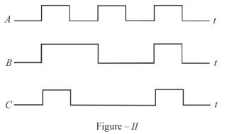
Figure-I shows a logic circuit with two inputs A and B and output C. The voltage incorrect waveform of A, B and C are shown in figure-II. The logic circuit is :



When an input electrical signal A = 10100 is applied to a NOT gate, its output signal is :
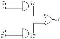
The output Y from the following logic gate circuit will be :
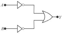
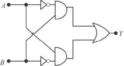
The Boolean expression of the output Y in terms of the inputs A and B for the circuit shown in the following figure is.
The binary number 110000111101 corresponds to a hexadecimal number.
Figure I shows a two input type of logic circuit where A and B are the inputs and C is the output. The truth table of the logic gate is shown in Figure II.
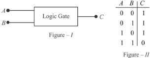
Which one of the following logic gate does the given truth table represent?

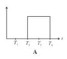
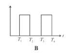
The given figure shows the wave forms for two inputs A and B and that for the output V of logic circuit. The logic circuit is :

The truth table for the input NAND gate is given by :


 will be equal to.


 where A is the input.

