Electromagnetic Induction MSQ - Physics MCQ
10 Questions MCQ Test Topic wise Tests for IIT JAM Physics - Electromagnetic Induction MSQ
If a conductor 0.2m long moves with a velocity of 0.3m/s in a magnetic field of 5T, calculate the emf induced if magnetic field, velocity and length of conductor are mutually perpendicular to each other.
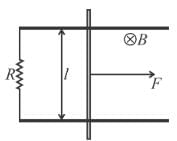
A constant force F is being applied on a rod of length ‘l’ kept at rest on two parallel conducting rails connected at ends by resistance R in uniform magnetic field B as shown. Which of the following statement is incorrect.

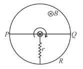
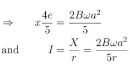
In the figure shown ‘R’ is a fixed conducting fixed ring of negligible resistance and radius ‘a’. PQ is a uniform rod of resistance r. It is hinged at the centre of the ring and rotated about this point in clockwise direction with a uniform angular velocity ω. There is a uniform magnetic field of strength ‘B’ pointing inwards ‘r’ is a stationary resistance

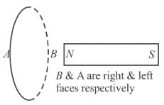
In the figure shown, the magnet is pushed towards the fixed ring along the axis of the ring and it passes through the ring. Which of the following is incorrect.
An ideal inductor, (having initial current zero) a resistor and an ideal battery are connected in series at time t = 0. At any time t, the battery supplies energy at the rate PB, the resistor dissipates energy at the rate PR and the inductor stores energy at the rate PL.
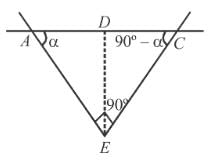
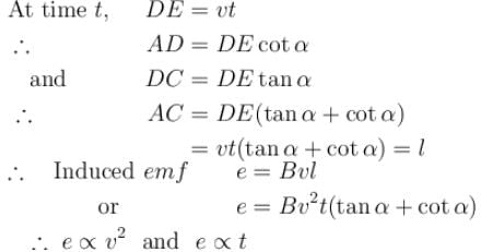
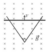
Two straight conducting rails form a right angle where their ends are joined. A conducting bar in contact with the rails starts at the vertex at time t = 0 and moves with constant velocity v along them as shown in figure. A magnetic field  is directed into the page. The induced emf in the circuit at any time t is proportional to
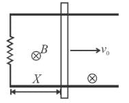
A conducting rod of length l is moved at constant velocity ‘v0’ on two parallel, conducting, smooth, fixed rails, that are placed in a uniform constant magnetic field B perpendicular to the plane of the rails as shown in figure. A resistance R is connected between the two ends of the rail. Then which of the following is/are correct:
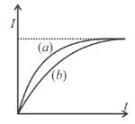
A circuit consisting of a constant emf. ‘E’, a self induction ‘L’ and a resistance ‘R’ is closed at t = 0. The relation between the current I in the circuit and time t is as shown by curve ‘a’ in the figure. When one or more of parameters E, R and L are changed, the curve ‘b’ is obtained. The steady state current is same in both the cases. Then it is possible that
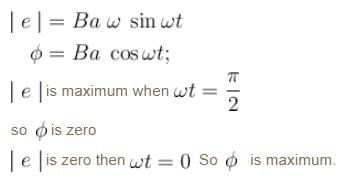
A conducting loop rotates with constant angular velocity about its fixed diameter in a uniform magnetic field. Whose direction is perpendicular to that fixed diameter.


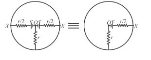

 Direction of current in external ‘r’ is from circumference to centre
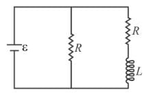


 for all times t,
  only near the starting of the circuit
