OP AMP MCQ Level – 2 - Physics MCQ
10 Questions MCQ Test - OP AMP MCQ Level – 2
The circuit connection of Op-Amp given in the figure (i) and (ii) represent


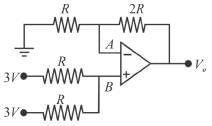
Given the circuit below, calculate the output voltage of the non-inverting Op-Amp summer:

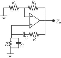
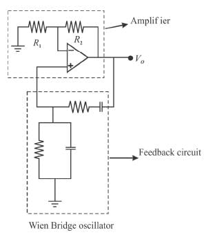
What should be the values of the component R and R2 such the frequency of the Wien bridge oscillator is 300Hz?
(given C = 0.01 μf and R1 = 12kΩ.
(given C = 0.01 μf and R1 = 12kΩ.

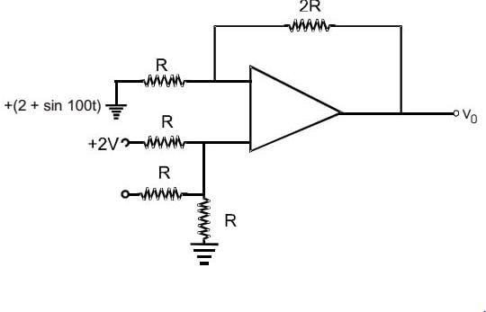
A non-inverting Op-Amp summer is shown in the figure. The output voltage V0 is
When negative feedback is used, then the gain bandwidth product of an Op-Amp.
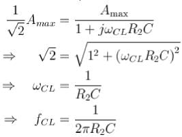
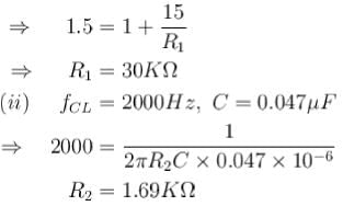
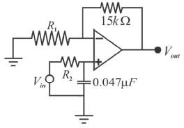
The low-pass active filter shown in the figure has a cut-off frequency of 2kHz and a pass band gain of 1.5. The values of the resistors are :
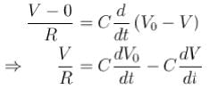
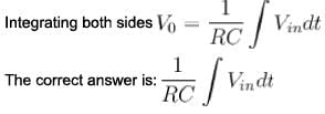
The circuit below represent a non-inverting integrator. Find the expression for the output voltage.
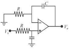
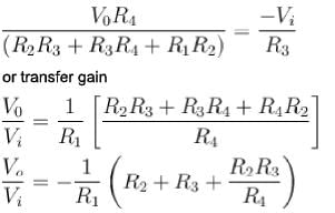
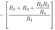
The transistor gain of the circuit shown in figure is given by
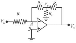
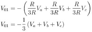
The output voltage at the end of second amplifier V01 is :
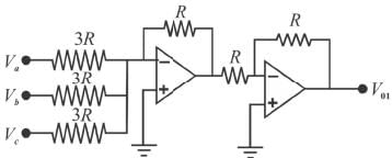
The following circuit contains 3 Op-Amps and resistors.
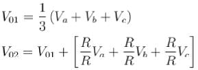
The output V02 (at the end of third Op-Amp) of the below circuit is :
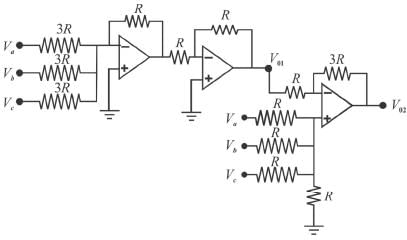




 of its low frequency value)
