NEET Exam  >  NEET Tests  >  Topic-wise MCQ Tests for NEET  >  Test: Alternating Current - 3 - NEET MCQ

Test: Alternating Current - 3 - NEET MCQ


Test Description

25 Questions MCQ Test Topic-wise MCQ Tests for NEET - Test: Alternating Current - 3

Test: Alternating Current - 3 for NEET 2024 is part of Topic-wise MCQ Tests for NEET preparation. The Test: Alternating Current - 3 questions and answers have been prepared according to the NEET exam syllabus.The Test: Alternating Current - 3 MCQs are made for NEET 2024 Exam. Find important definitions, questions, notes, meanings, examples, exercises, MCQs and online tests for Test: Alternating Current - 3 below.
Solutions of Test: Alternating Current - 3 questions in English are available as part of our Topic-wise MCQ Tests for NEET for NEET & Test: Alternating Current - 3 solutions in Hindi for Topic-wise MCQ Tests for NEET course. Download more important topics, notes, lectures and mock test series for NEET Exam by signing up for free. Attempt Test: Alternating Current - 3 | 25 questions in 50 minutes | Mock test for NEET preparation | Free important questions MCQ to study Topic-wise MCQ Tests for NEET for NEET Exam | Download free PDF with solutions
Test: Alternating Current - 3 - Question 1

In an a.c. circuit voltage V and current i are given by V = 100 sin 100 t volts, i = 100 sin (100t + p/3) mA. The power dissipated in the circuit is :

Detailed Solution for Test: Alternating Current - 3 - Question 1

Vrms = 100/√2 V
Irms = 100/√2 mA
= 10-1/√2 A
π/3 = 30º
Average power = Vrms×Irms× cos
= (100/√2)×(10-1√2)× cos 30º
= 10/2×(1/2)
= 10/4
= 2.5W

Test: Alternating Current - 3 - Question 2

The potential difference V and current i flowing through an a.c. circuit are given by V = 5 cos wt volt, i = 2 sin wt amp. the power dissipated in the circuit.

Detailed Solution for Test: Alternating Current - 3 - Question 2

The voltage can be written as,
V=5[sinωt+(π/2​)]
The angle between the voltage and the current is 90∘.
The power dissipated in the circuit is given as,
P=Vrms​Irms​cosϕ
=Vrms​Irms​cos90o
=0
Thus, the power dissipated in the circuit is 0.
 

1 Crore+ students have signed up on EduRev. Have you? Download the App
Test: Alternating Current - 3 - Question 3

An a.c. circuit consists of an inductor of inductances 0.5 H and a capacitor of capacitance 8 mF in series. The current in the circuit is maximum when the angular frequency of an a.c. source is

Detailed Solution for Test: Alternating Current - 3 - Question 3

Given,
Inductance and capacitance are joined in series, and inductance L=0.5H,
And capacitance C=8μF=8×10⁻⁶F.
We know that,
ω=1/√(LC)
ω=1/√(8×10−6×0.5)=1/(2×10−3)=0.5×103HZ=500HZ

Test: Alternating Current - 3 - Question 4

The rms value of an AC of 50 Hz is 10 amp. The time taken by an alternating current in reaching from zero to maximum value and the peak value will be ;

Detailed Solution for Test: Alternating Current - 3 - Question 4

Time taken by alternating current to reach maximum from zero is 4T​.
where T is the time period of the AC function.
T=1/f​, Frequency (f)=50 Hz.
So time taken to reach maximum=T/4​=1/4f​=1/(4×50)​=5×10−3 sec
IRMS​=​I0/√2​, I0​=Peak value of current.
Peak value of current I0​=√2​×IRMS​=√2​×10=14.14 A
 

Test: Alternating Current - 3 - Question 5

A voltage of peak value 283 V varying frequency is applied to a series L-C-R combination in which R = 3W; L = 25 mH and C = 400 mF. Then, the frequency (in Hz) of the source at which maximum power is dissipated in the above, is
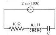
Detailed Solution for Test: Alternating Current - 3 - Question 5

Here, V0​=283V,R=3Ω,L=25×10−3H
C=400μF=4×10⁻⁴F
Maximum power is dissipated at resonance, for which 
 
ν=1/[2π√(LC)]​​= (1×7​)/[2×22(25×10−3×4×10−4)]
=(7×10³​)/(44√10​)
=50.3Hz

Test: Alternating Current - 3 - Question 6

The power factor of the circuit is 1/. The capacitance of the circuit is equal to


Detailed Solution for Test: Alternating Current - 3 - Question 6

Here, it is given that,
power factor in the circuit, = 1/√2
Resistance, R = 10Ω
inductance, L = 0.1 H
Supply voltage, V = 2sin(100t)
peak voltage, V₀ = 2
ω = 100 rad/s
capacitance = ?
=> power factor = cos∅ = R/Z
1/√2 = 10/Z
=> By Taking the square on both the sides,
1/2 = 100/Z2
Z2 = 200
=> Now, we can use below formula to calculate the capacitance of the circuit.
R2 + (Xc - XL)2 = Z2
10² + (1 / cω - Lω)² = 200
(1/cω - Lω)2 = 100
1/cω - Lω = 10
1/cω = Lω + 10
1/cω = 0.1 * 100 + 10
1/cω = 20
c = 1/(20xω)
c = 1/(20x100)
c = 1/2000 F
c = 106 / 2000 (μ)F    [∵ 1 F = 106 (μ)F ]
= 500 (μ) F


Test: Alternating Current - 3 - Question 7

An ac-circuit having supply voltage E consists of a resistor of resistance 3W and an inductor of reactance 4W as shown in the figure. The voltage across the inductor at t = p/w is


Detailed Solution for Test: Alternating Current - 3 - Question 7

Here,
XL = 4 Ω
R = 3 Ω
Z = √(XL2 + R2)=√(42 + 32)
  = 5 Ω
E0 = 10 V
In the LR circuit current in the ckt is given by
I = (E0/Z)sin(ωt - Φ)
Φ = tan-1(XL/R)
=>  Φ = tan-1(4/3)
I = (E0/Z)sin(ωt - Φ)
  = (10/5) sin(ωt - Φ)
I at t = T/2
  = 2sin(ωT/2 – Φ)
 =  2sin(π - Φ)
  = 2sin(tan-1(4/3))
  = 2×0.8
  = 1.6 A
Potential difference across the resistor = 1.6×R
   = 1.6×3
   = 4.8 V
Potential difference across the inductor = 1.6XL
      = 1.6×4 = 6.4 V

Test: Alternating Current - 3 - Question 8

 When 100 V DC is applied across a solenoid a current of 1A flows in it. When 100 V AC is applied across the same coil, the current drops to 0.5 A. If the frequency of the AC source is 50 Hz, the impedance and inductance of the solenoid are :

Detailed Solution for Test: Alternating Current - 3 - Question 8

Impedance= Vac/Iac​ ​​=100V/0.5A ​=200Ω
R= Vdc​​/Idc ​ =100/1​=100Ω
Lω =√ (impedance2−R2​)=√(2002−1002​)=173.2
L=173.2/ ω​= 173.2/2π50​=0.55H
 

Test: Alternating Current - 3 - Question 9

An inductive circuit contains a resistance of 10 ohm and an inductance of 2.0 henry. If an ac voltage of 120 volt and frequency of 60 Hz is applied to this circuit, the current in the circuit would be nearly :

Detailed Solution for Test: Alternating Current - 3 - Question 9

i= E/√[R2+(2πfL)2]​
​=120/√[100+(753.6)2]​
​=120​/753.66
=0.1592≅0.16Amp

Test: Alternating Current - 3 - Question 10

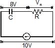
 In the circuit shown if the emf of source at an instant is 5V, the potential difference across capacitor at the same instant is 4V. The potential difference across R at that instant may be


Detailed Solution for Test: Alternating Current - 3 - Question 10

Test: Alternating Current - 3 - Question 11

Let f = 50 Hz, and C = 100 mF in an AC circuit containing a capacitor only. If the peak value of the current in the circuit is 1.57 A at t = 0. The expression for the instantaneous voltage across the capacitor will be

Detailed Solution for Test: Alternating Current - 3 - Question 11

Peak value of voltage
V0=i0XC =i0/2πvC
=>1.57/(2x3.14x50x100x10-6)
Hence if equation of current i = io sin ω t then in capacitive circuit voltage is 
V=V0 (ωt -  π/2)
=>50[sin2π x50t- (π/2)]
 =50[100πt-(π/2)]


Test: Alternating Current - 3 - Question 12

In a series CR circuit shown in figure, the applied voltage is 10 V and the voltage across capacitor is found to be 8V. Then the voltage across R, and the phase difference between current and the applied voltage will respectively be


Detailed Solution for Test: Alternating Current - 3 - Question 12

VR​=√ [V2−VC2​​]=√ [(10)2−(8)2]​=6V
tanϕ= XC/XR​ ​​= VC​​/VR​ =8/6​=4/3​

Test: Alternating Current - 3 - Question 13

The phase difference between current and voltage in an AC circuit is p/4 radian. If the frequency of AC is 50 Hz, then the phase difference is equivalent to the time difference :

Detailed Solution for Test: Alternating Current - 3 - Question 13
The period of a whole cycle at 50Hz is 1/50 = 0.02 Seconds.(This is the time it would take a generator rotor to complete one rotation).That is a full circle 2π radians (or 360 Degrees).
The phase difference (angle between curent and voltage) is π/4 part of this circle.That corresponds to 0.02 Seconds * (π/4) / (2 π) = 0.02 Seconds * 1/8 = 0.0025 Seconds.Or 2.5 milliseconds.So, the current vector leads (or lags) the voltage vector by 2.5 milli seconds.
Test: Alternating Current - 3 - Question 14

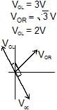
The given figure represents the phasor diagram of a series LCR circuit connected to an ac source. At the instant t' when the source voltage is given by V = V0coswt, the current in the circuit will be


Test: Alternating Current - 3 - Question 15

 Power factor of an L-R series circuit is 0.6 and that of a C_R series circuit is 0.5. If the element (L, C, and R) of the two circuits are joined in series the power factor of this circuit is found to be 1. The ratio of the resistance in the L-R circuit to the resistance in the C-R circuit is

Detailed Solution for Test: Alternating Current - 3 - Question 15

cosϕ1=0.6=5/3
tanϕ1=4/3= XC/R2…(1)
cosϕ1=0.5=1/2
tanϕ2=√3= R2/XC…(2)
From (1) and (2)3√3/4=R1/R2

Test: Alternating Current - 3 - Question 16

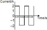
The direct current which Would give the same heating effect in an equal constant resistance as the current shown in figure, i.e. the r.m.s. current, is


Test: Alternating Current - 3 - Question 17

The effective value of current i = 2 sin 100p t + 2 sin (100pt + 30º) is

Detailed Solution for Test: Alternating Current - 3 - Question 17

cosθ=sin(90o−θ)
sinα+sinβ=2sin (α+β/2)​cos (α−β​/2)
i=2sin100πt+2cos(100πt+30o)
=2sin100πt+2sin(90o−(100πt+30o))
=2sin100πt+2sin(60o−100πt)
=2 x 2 x sin [{(100−100)πt+60o }/2] x cox[(100+100)πt−60o/2]
​=4 x sin30o∗cos(100πt−30o)
=4x(1/2) x cos(100πt−30o)
=2cos(100πt−30o)
therefore, Io​=2A
Irms​=2 / √2​= √2​A

Test: Alternating Current - 3 - Question 18

A student in a lab took a coil and connected it to a 12 V DC source. He measures the steady state current in the circuit to be 4A. He then replaced the 12 V DC source by a 12 V, (w = 50 rad/s) AC source and observes that the reading in the AC ammeter is 2.4 A. He then decides to connect a 2500 mF capacitor in series with the coil and calculate the average power developed in the circuit. Further he also decides to study the variation in current in the circuit (with the capacitor and the battery in series).

Based on the readings taken by the student answer the following questions.

The value of resistance of the coil calculated by the student is

Test: Alternating Current - 3 - Question 19

A student in a lab took a coil and connected it to a 12 V DC source. He measures the steady state current in the circuit to be 4A. He then replaced the 12 V DC source by a 12 V, (w = 50 rad/s) AC source and observes that the reading in the AC ammeter is 2.4 A. He then decides to connect a 2500 mF capacitor in series with the coil and calculate the average power developed in the circuit. Further he also decides to study the variation in current in the circuit (with the capacitor and the battery in series).

Based on the readings taken by the student answer the following questions.

The power developed in the circuit when the capacitor of 2500 mF is connected in series with the coil is

Detailed Solution for Test: Alternating Current - 3 - Question 19

VDC=IDCR
∴R=VDC/IDC=12/4=3Ω
IAC=VAC/Z=VAC√(R2+XL2)
2.4=12√ [(3)2+XL2]
solving this equation, we get,
XL=4Ω
XC=1/ωC=1/(50×2500×10−6)
=8Ω
Z=√[R2+(XC−XL)2] =5Ω
∴I=VDC/Z=12/5=2.4A=Irms
P=Irms2R=(2.4)2(3)
=17.28W
At given frequency XC>XL if omega is further decreased XC will increase (as XC∝1/ω) and XL will increase (as XL∝ω).
Therefore XC−XL and hence Z will increase. So, current will decrease.

Test: Alternating Current - 3 - Question 20

A student in a lab took a coil and connected it to a 12 V DC source. He measures the steady state current in the circuit to be 4A. He then replaced the 12 V DC source by a 12 V, (w = 50 rad/s) AC source and observes that the reading in the AC ammeter is 2.4 A. He then decides to connect a 2500 mF capacitor in series with the coil and calculate the average power developed in the circuit. Further he also decides to study the variation in current in the circuit (with the capacitor and the battery in series).

Based on the readings taken by the student answer the following questions.

Which of the following graph roughly matches the variations of current in the circuit (with the coil and capacitor connected in the series) when the angular frequency is decreased from 50 rad/s to 25 rad/s ?

Detailed Solution for Test: Alternating Current - 3 - Question 20

VDC=IDCR
∴R=VDC/IDC=12/4=3Ω
IAC=VAC/Z=VAC√(R2+XL2)
2.4=12√ [(3)2+XL2]
solving this equation, we get,
XL=4Ω
XC=1/ωC=1/(50×2500×10−6)
=8Ω
Z=√[R2+(XC−XL)2] =5Ω
∴I=VDC/Z=12/5=2.4A=Irms
P=Irms2R=(2.4)2(3)
=17.28W
At given frequency XC>XL if omega is further decreased XC will increase (as XC∝1/ω) and XL will increase (as XL∝ω).
Therefore XC−XL and hence Z will increase. So, current will decrease.

Test: Alternating Current - 3 - Question 21

 If a direct current of value 'a' ampere is superimposed on an alternating current I = b sin wt flowing through a wire, what is the effective (rms) value of the resulting current in the circuit ?


*Answer can only contain numeric values
Test: Alternating Current - 3 - Question 22

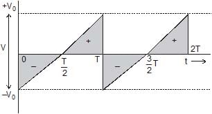
 Find the average for the saw-tooth voltage of peak value V0 from t = 0 to t = 2T as shown in figure.


Test: Alternating Current - 3 - Question 23

 A circuit has a coil of resistance 50 ohms and inductance  henry. It is connected in series with a condenser of  m F and AC supply voltage of 200 V and 50 cycles/sec. Calculate

(i) the impedance of the circuit. (ii) the p.d. across inductance coil and condenser.


*Answer can only contain numeric values
Test: Alternating Current - 3 - Question 24

 A series circuit consists of a resistance, inductance and capacitance. The applied voltage and the current at any instant are given by E = 141.4 cos (5000 t _ 10°) and I = 5 cos (5000 t _ 370°) The inductance is 0.01 henry. Calculate the value of capacitance and resistance.


Test: Alternating Current - 3 - Question 25

A circuit takes A current of 3 a at a power factor of 0.6 lagging when connected to a 115 V _ 50 Hz supply. Another circuit takes a current of 5A at a power factor of 0.07 leading when connected to the same supply. If the two circuits are connected in series across a 230 V, 50 Hz supply. Calculate

(a) the current (b) the power consumed and (c) the power factor.


9 docs|1272 tests
Information about Test: Alternating Current - 3 Page
In this test you can find the Exam questions for Test: Alternating Current - 3 solved & explained in the simplest way possible. Besides giving Questions and answers for Test: Alternating Current - 3, EduRev gives you an ample number of Online tests for practice

Top Courses for NEET

Download as PDF

Top Courses for NEET