Electronics and Communication Engineering (ECE) Exam  >  Electronics and Communication Engineering (ECE) Tests  >  GATE ECE (Electronics) Mock Test Series 2025  >  Test: Comparators - Electronics and Communication Engineering (ECE) MCQ

Test: Comparators - Electronics and Communication Engineering (ECE) MCQ


Test Description

10 Questions MCQ Test GATE ECE (Electronics) Mock Test Series 2025 - Test: Comparators

Test: Comparators for Electronics and Communication Engineering (ECE) 2024 is part of GATE ECE (Electronics) Mock Test Series 2025 preparation. The Test: Comparators questions and answers have been prepared according to the Electronics and Communication Engineering (ECE) exam syllabus.The Test: Comparators MCQs are made for Electronics and Communication Engineering (ECE) 2024 Exam. Find important definitions, questions, notes, meanings, examples, exercises, MCQs and online tests for Test: Comparators below.
Solutions of Test: Comparators questions in English are available as part of our GATE ECE (Electronics) Mock Test Series 2025 for Electronics and Communication Engineering (ECE) & Test: Comparators solutions in Hindi for GATE ECE (Electronics) Mock Test Series 2025 course. Download more important topics, notes, lectures and mock test series for Electronics and Communication Engineering (ECE) Exam by signing up for free. Attempt Test: Comparators | 10 questions in 30 minutes | Mock test for Electronics and Communication Engineering (ECE) preparation | Free important questions MCQ to study GATE ECE (Electronics) Mock Test Series 2025 for Electronics and Communication Engineering (ECE) Exam | Download free PDF with solutions
Test: Comparators - Question 1

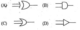
Identify the 1 – bit comparator circuit 

Detailed Solution for Test: Comparators - Question 1

Comparator: 
A comparator is a combinational circuit that gives the output in terms of input signals.
It is used to compare numbers and represent their relationship with each other.
It compares the signals as A > B, A < B, and A = B.
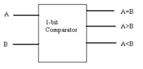
1-bit comparator:
A 1-bit comparator circuit is shown below.

In this circuit, we can compare two input signals
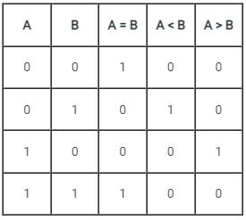
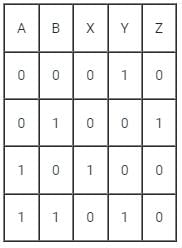
The truth table for the 1-bit comparator is

The expression for A = B: A ⊙ B
The expression for A > B: A B̅ 
The expression for A < B: A̅ B

Test: Comparators - Question 2

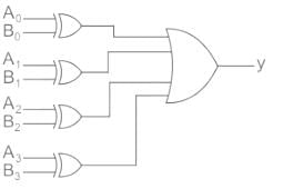
A digital circuit which compares two numbers A3 A2 A1 A0, B3 B2 B1 B0 is shown in figure. To get output Y = 1, the correct pair of input numbers are
Detailed Solution for Test: Comparators - Question 2


Y = (A0 ⊕ B0) + (A1 ⊕ B1) + (A2 ⊕ B2) + (A3 ⊕ B3
Given that output is 1.
To get the output y = 1, all the inputs of OR gate should not be zero.
From the options, A3 A2 A1 A0 = 0010, B3 B2 B1 B0 = 1011 satisfies this condition.

1 Crore+ students have signed up on EduRev. Have you? Download the App
Test: Comparators - Question 3

X = X1X0 and Y = Y1Y0 are 2-bit binary numbers. The Boolean function S that satisfies the condition “If X > Y, then S = 1”, in its minimized form, is

Detailed Solution for Test: Comparators - Question 3

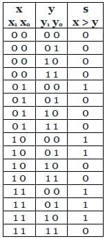
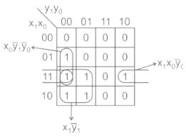
x = x1 x0 y = y1 y0
The Boolean function S that satisfies condition,
If x > y, then s = 1.
We can represent the above condition through a truth table.

By using k-maps

Minimized form:
s = x11 + x1x00 + x010  

Test: Comparators - Question 4

Maximum conversion time in clock cycles for three types of 8 bit ADCs (i) Successive approximation, (ii) Dual slope and (iii) Parallel comparator are respectively

Detailed Solution for Test: Comparators - Question 4

Concept:
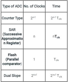
The conversion time of different types of n-bit ADC is shown :

  • From the above table, it is clear that the dual-slope is the slowest ADC and Flash Type is the fastest ADC.
  • The conversion type of Flash type is independent of the number of bits 

Application:
n = 8

  • Maximum conversion time in clock cycles of 8-bit Successive approximation type ADC  = n=  8
  • Maximum conversion time in clock cycles of 8 bit Dual slope type ADC = 2n+1 = 29 = 512
  • Maximum conversion time in clock cycles of 8 bit Successive approximation type ADC = 1
Test: Comparators - Question 5

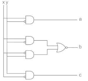
The circuit shown in the figure is a –

Detailed Solution for Test: Comparators - Question 5

From the given circuit we can find the outputs expression as follows:

Now, we can observe that

So, the given circuit in question behaves like a comparator circuit. 

Test: Comparators - Question 6

Circuit for comparing 2 n-bit numbers has ____ entries in truth table

Detailed Solution for Test: Comparators - Question 6

In an n-bit, compare the n columns of bits in one binary number (let it be A) and n columns of bits of another number (let it be B).
For all possible values of bits in A and B truth table is taken for A > B, A < B and A = B.
So there are 2n inputs in the comparator.
For 2n inputs total possible combinations are 22n
So total number of entries is 22n.

Test: Comparators - Question 7

The given below logic circuit will work as

Detailed Solution for Test: Comparators - Question 7


By analysing the above truth table it is giving the expression for 1 bit comparator.

Test: Comparators - Question 8

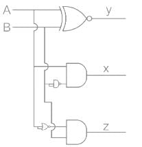
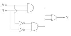
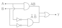
The logic circuit of the figure is a

Detailed Solution for Test: Comparators - Question 8

Y = AB + A̅B̅
It represents a XNOR gate
The truth table of XNOR gate is


The output is high when both the inputs are equal.
It represents a 1-bit comparator (or) equality detector.

Test: Comparators - Question 9

The output Y of a 2-bit comparator is logic 1 whenever the 2-bit input A is greater than the 2-bit input B. The number of combinations for which the output is logic 1, is

Detailed Solution for Test: Comparators - Question 9

The only possible combinations are
A = 01 and B = 0 0
A = 10 and B = 00, 01
A = 11 and B = 00, 01, 10
So there are only 6 combinations
Tips and Tricks:

where n = 2 bit

Test: Comparators - Question 10

A 3 bit comparator circuit gives logic 1 output whenever the 3 bit input A is greater than the 3 bit input B. The output Boolean function y is represented by a K-map. The no. of 1 in the K-map is –

Detailed Solution for Test: Comparators - Question 10

Total no. of input combination of A & B are = 23 x 23 = 64
In 64 combination only in 8 combination A = B situation occurs. So the no. of combination for which A ≠ B is 64 - 8 = 56
Only of these 56 combinations only in 28 combinations A > B situation occur.
So, the no of 1 in K map will be 28

25 docs|263 tests
Information about Test: Comparators Page
In this test you can find the Exam questions for Test: Comparators solved & explained in the simplest way possible. Besides giving Questions and answers for Test: Comparators, EduRev gives you an ample number of Online tests for practice

Top Courses for Electronics and Communication Engineering (ECE)

Download as PDF

Top Courses for Electronics and Communication Engineering (ECE)