Electronics and Communication Engineering (ECE) Exam  >  Electronics and Communication Engineering (ECE) Tests  >  Electronic Devices  >  Test: Configuration of BJT - Electronics and Communication Engineering (ECE) MCQ

Test: Configuration of BJT - Electronics and Communication Engineering (ECE) MCQ


Test Description

10 Questions MCQ Test Electronic Devices - Test: Configuration of BJT

Test: Configuration of BJT for Electronics and Communication Engineering (ECE) 2024 is part of Electronic Devices preparation. The Test: Configuration of BJT questions and answers have been prepared according to the Electronics and Communication Engineering (ECE) exam syllabus.The Test: Configuration of BJT MCQs are made for Electronics and Communication Engineering (ECE) 2024 Exam. Find important definitions, questions, notes, meanings, examples, exercises, MCQs and online tests for Test: Configuration of BJT below.
Solutions of Test: Configuration of BJT questions in English are available as part of our Electronic Devices for Electronics and Communication Engineering (ECE) & Test: Configuration of BJT solutions in Hindi for Electronic Devices course. Download more important topics, notes, lectures and mock test series for Electronics and Communication Engineering (ECE) Exam by signing up for free. Attempt Test: Configuration of BJT | 10 questions in 30 minutes | Mock test for Electronics and Communication Engineering (ECE) preparation | Free important questions MCQ to study Electronic Devices for Electronics and Communication Engineering (ECE) Exam | Download free PDF with solutions
Test: Configuration of BJT - Question 1

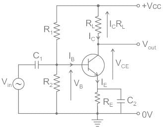
In a common-emitter amplifier, the input AC signal to be amplified is applied across:

Detailed Solution for Test: Configuration of BJT - Question 1
  • Amplifier: An electronic device that increases the voltage, current, or power of a signal is called an amplifier.
    • Amplifiers are used in wireless communications and broadcasting, and in audio equipment of all kinds.
  • Common emitter amplifier: It is a three basic single-stage bipolar junction transistor and is used as a voltage amplifier.

  • The input is applied to the base, and the output is taken from the collector, the common terminal for both circuits is the emitter.

The correct option is 1.

Test: Configuration of BJT - Question 2

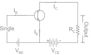
Which of the following is true for the common emitter configuration of BJT, with usual notations? 

Detailed Solution for Test: Configuration of BJT - Question 2


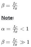
The base current amplification factor in CE configuration is denoted by the symbol β which is the ratio of change in collector current (ΔIC) to the change in base current (ΔIB).

1 Crore+ students have signed up on EduRev. Have you? Download the App
Test: Configuration of BJT - Question 3

Identify the correct statement/s.
I. The other name for the common collector amplifier is emitter follower.
II. Power gain of the common emitter amplifier is high.

Detailed Solution for Test: Configuration of BJT - Question 3
  • The common collector transistor circuit configuration gains its name from the fact that the collector circuit is common to both input and output circuits, the base is associated with only the input, and then the emitter with the output only.
  • The other name for the common collector is emitter follower. This name is derived from the fact that the emitter voltage "follows" that of the base circuit - the circuit has unit voltage gain.
  • The emitter follower transistor amplifier has a very straightforward circuit. The base is connected to the previous stage, and often this may be directly connected as this can save on additional bias resistors which lower the input impedance and hence increase the loading to the previous stage.
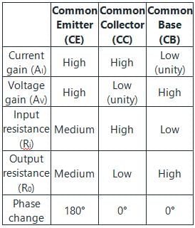
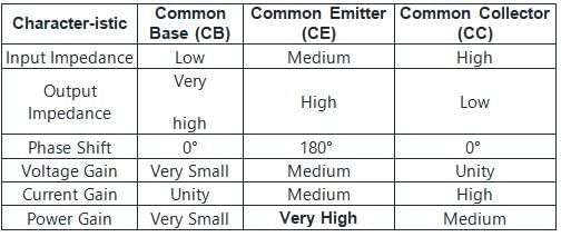
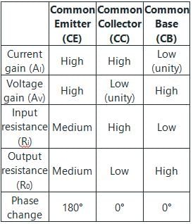
  • The power gain of a common emitter (CE) amplifier is higher than the power gain of a common collector (CC) amplifier or a common base (CB) amplifier


Test: Configuration of BJT - Question 4

When the EB junction of a transistor is reverse biased then collector current 

Detailed Solution for Test: Configuration of BJT - Question 4

When the emitter-base (EB) junction of a transistor is reverse-biased, the collector current typically becomes very small or approaches zero. Therefore, the correct answer is 1
Concept:

  • In a normal operating condition, when the emitter-base junction of a transistor is forward-biased, it allows current to flow from the emitter to the base. This forward biasing establishes the necessary conditions for the transistor to function as an amplifier or switch.
  • However, when the emitter-base junction is reverse-biased (reverse voltage applied), the depletion region of the junction widens, making it difficult for the majority carriers to cross the junction. As a result, the flow of current from the collector to the emitter is significantly reduced.
  • In this reverse-biased condition, only a small amount of leakage current may flow through the junction due to minority carriers (minority carrier leakage), but the collector current is typically negligible or considered close to zero.
Test: Configuration of BJT - Question 5

Which of the following BJT configuration has highest Power Gain?

Detailed Solution for Test: Configuration of BJT - Question 5

Test: Configuration of BJT - Question 6

Which of the following statement/s is /are correct regarding the CB Configuration amplifier?
A). Current gain of an ideal Common base amplifier is unity.
B). Voltage gain is unity.
C). The Phase between input and output is 180º.

Detailed Solution for Test: Configuration of BJT - Question 6

Current gain(α) of a Common base amplifier is unity (ideally).
The Input resistance is very low ( 30-150 Ω ).
The output resistance is very high ( ≈ 500K ).
The Voltage gain is high.
The Phase between input and output is the same.

Test: Configuration of BJT - Question 7

For a transistor connected in common base connection, collector current is 0.95 mA and base current is 0.05 mA. Find the value of α :

Detailed Solution for Test: Configuration of BJT - Question 7

For a transistor, the base current, the emitter current, and the collector current are related as:
IE = IB + IC
where IC = αIE
α = Current gain of the transistor
Calculation:
Given,
IC = 0.95 mA
IB = 0.05 mA
∴ IE = IB + IC = 0.05 + 0.95 = 1 mA
From the above concept,
IC = αIE

Test: Configuration of BJT - Question 8

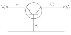
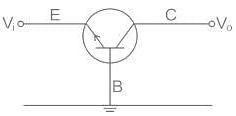
In a Common Base Configuration, BJT has _______ input impedance and ________output impedance. 

Detailed Solution for Test: Configuration of BJT - Question 8

Common base configuration:

Input Terminal Emitter – Base (EB)
Output Terminal Collector – Base (CB)
Since for Amplification Application in BJT
EB Junction → Forward Biased (Low Impedance)
CB Junction → Reversed Biased (High Impedance)
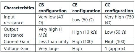
Various transistor configurations and their characteristics are shown in the table

Test: Configuration of BJT - Question 9

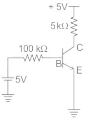
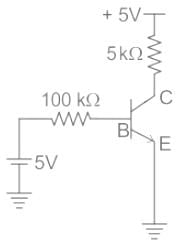
The transistor(β = 100) as shown in the circuit is operating in:
Detailed Solution for Test: Configuration of BJT - Question 9

Region of operation of BJT:
In a given circuit, the region of the transistor can be decided through the following procedure.

  • Assume that the transistor is in the saturation region.
  • Calculate Base current (IB) and collector current (IC) separately.
  • Calculate the minimum Base current (IB)min required to operate the transistor in saturation.
  • Compare Base current (IB) and (IB)min

IB  ≥   (IB)min, Transistor is in the Saturation region.
IB < (IB)min, Transistor is in the Active region
IB  < 0, Transistor is in the Cut-off region.
Formula:
In saturation,
Base-Emitter voltage = VBE = 0.8 V
Collector-Emitter voltage VCE = 0.2 V
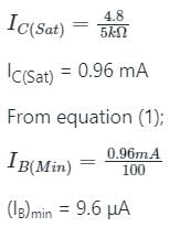
(IB)min = (IC)sat / β  ----(1)
(IC)sat  = Collector current in Saturation 
β = DC current gain

Assume transistor in Saturation region.
Apply KVL in the outer loop:
5 - IC(Sat) x 5kΩ - VCE(Sat) = 0

Now, Apply KVL in Emitter Loop; 

Hence, BJT is in saturation region.

Test: Configuration of BJT - Question 10

In CB configuration of transistor, the output impedance is:

Detailed Solution for Test: Configuration of BJT - Question 10

Common base configuration:

Input Terminal Emitter – Base (EB)
Output Terminal Collector – Base (CB)
Since for Amplification Application in BJT
EB Junction → Forward Biased (Low Impedance)
CB Junction → Reversed Biased (High Impedance)

21 docs|29 tests
Information about Test: Configuration of BJT Page
In this test you can find the Exam questions for Test: Configuration of BJT solved & explained in the simplest way possible. Besides giving Questions and answers for Test: Configuration of BJT, EduRev gives you an ample number of Online tests for practice

Top Courses for Electronics and Communication Engineering (ECE)

Download as PDF

Top Courses for Electronics and Communication Engineering (ECE)