Electronics and Communication Engineering (ECE) Exam  >  Electronics and Communication Engineering (ECE) Tests  >  GATE ECE (Electronics) Mock Test Series 2025  >  Test: Digital Electronics- 3 - Electronics and Communication Engineering (ECE) MCQ

Test: Digital Electronics- 3 - Electronics and Communication Engineering (ECE) MCQ


Test Description

25 Questions MCQ Test GATE ECE (Electronics) Mock Test Series 2025 - Test: Digital Electronics- 3

Test: Digital Electronics- 3 for Electronics and Communication Engineering (ECE) 2024 is part of GATE ECE (Electronics) Mock Test Series 2025 preparation. The Test: Digital Electronics- 3 questions and answers have been prepared according to the Electronics and Communication Engineering (ECE) exam syllabus.The Test: Digital Electronics- 3 MCQs are made for Electronics and Communication Engineering (ECE) 2024 Exam. Find important definitions, questions, notes, meanings, examples, exercises, MCQs and online tests for Test: Digital Electronics- 3 below.
Solutions of Test: Digital Electronics- 3 questions in English are available as part of our GATE ECE (Electronics) Mock Test Series 2025 for Electronics and Communication Engineering (ECE) & Test: Digital Electronics- 3 solutions in Hindi for GATE ECE (Electronics) Mock Test Series 2025 course. Download more important topics, notes, lectures and mock test series for Electronics and Communication Engineering (ECE) Exam by signing up for free. Attempt Test: Digital Electronics- 3 | 25 questions in 75 minutes | Mock test for Electronics and Communication Engineering (ECE) preparation | Free important questions MCQ to study GATE ECE (Electronics) Mock Test Series 2025 for Electronics and Communication Engineering (ECE) Exam | Download free PDF with solutions
Test: Digital Electronics- 3 - Question 1

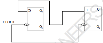
An X-Y flip flop whose characteristic table is given below is to be implemented using a T flip flop

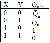
This can be done by making

Test: Digital Electronics- 3 - Question 2

Which of the following ADC has a fixed conversion time?

1 Crore+ students have signed up on EduRev. Have you? Download the App
Test: Digital Electronics- 3 - Question 3

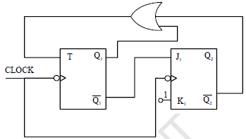
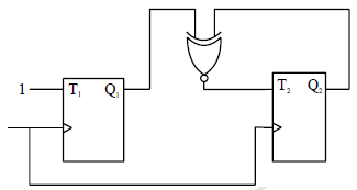
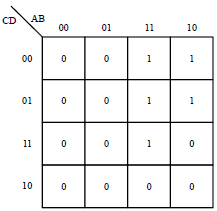
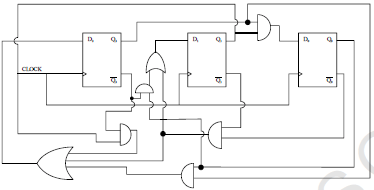
The sequence (Q2 Q1) when successive clock pulses are applied

Test: Digital Electronics- 3 - Question 4

A number P represented in signed binary 2’s complement form is 1001101. Another number Q1 represented in signed binary 2’s complement form is 11010111. If Q is subtracted from P, the result expressed in signed binary 2’s complement form

Test: Digital Electronics- 3 - Question 5

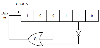
Figure shows the initial content of a 6 bit SIPO register with each clock pulse output of gate G1 is pushed in  the left most stage. What will be the content of the register after 9th clock pulse?

Test: Digital Electronics- 3 - Question 6

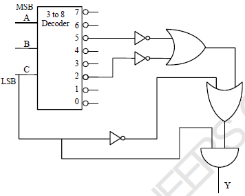
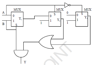
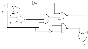
The function y (A, B, C) implemented by the circuit shown is

Test: Digital Electronics- 3 - Question 7

The output Y of the circuit shown is

Test: Digital Electronics- 3 - Question 8

The output voltage of the circuit shown

Test: Digital Electronics- 3 - Question 9

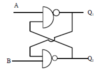
In the latch circuit shown if A = 1, B = 0 is applied, the corresponding stable outputs are

Test: Digital Electronics- 3 - Question 10

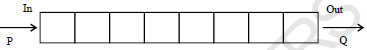
A digital bit is to be transmitted from point P to point Q by delaying it through a SISO register of 8 bit as shown. If the clock frequency used is 4 MHz, the delay created by the register is

Test: Digital Electronics- 3 - Question 11

Identify the incorrect statement

Detailed Solution for Test: Digital Electronics- 3 - Question 11

This statement is incorrect because as the number of steps increases, the resolution of the DAC increases, resulting in finer percentage resolution. Therefore, the statement should be: Percentage resolution increases as the number of steps increases.

Test: Digital Electronics- 3 - Question 12

The modulus of the circuit (Counter) shown is

Test: Digital Electronics- 3 - Question 13

The resistance corresponding to LSB in a weighted resistor 5 bit DAC i s 64 k?, then the resistor corresponding to MSB is

Test: Digital Electronics- 3 - Question 14

The output of a 6bit DAC for the digital input of 1001000 is 300 volts. What will be the DAC output for digital input 1101010 approximately

Test: Digital Electronics- 3 - Question 15

The simplified expression using kmap in POS form

Test: Digital Electronics- 3 - Question 16

The modulus of the counter circuit shown

Test: Digital Electronics- 3 - Question 17

In the circuit shown in figure, to make Low, what must be conditions at A and B

Test: Digital Electronics- 3 - Question 18

The number (123)7 in base 5 is equal to

Test: Digital Electronics- 3 - Question 19

The output y of the circuit shown is

Test: Digital Electronics- 3 - Question 20

The counting sequence (Q1 Q2) when clock pulses are applied 

Test: Digital Electronics- 3 - Question 21

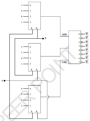
The binary equivalent of the gray code (1011100 11)G

Test: Digital Electronics- 3 - Question 22

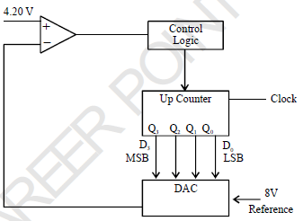
An analog input of 4.20 Volt is to be converted into digital form using counter type ADC. The digital equivalent will be [Taking threshold voltage of comparator as one tenth of DAC resolution)

Test: Digital Electronics- 3 - Question 23

The present state of a JK flip flop was 0. After one clock pulse, it was found to be 0. What possible inputs
may be applied?

Test: Digital Electronics- 3 - Question 24

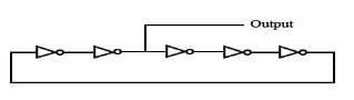
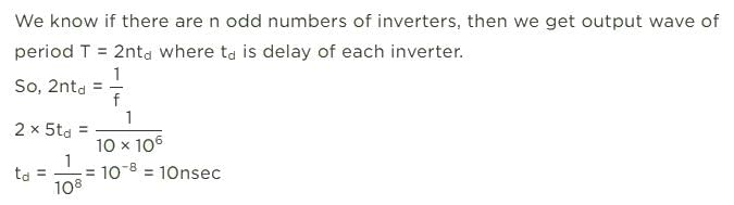
The inverters in the ring oscillator circuit shown below are identical. If the output waveform has a frequency of 10 MHz, the propagation delay of each inverter is

Detailed Solution for Test: Digital Electronics- 3 - Question 24

Test: Digital Electronics- 3 - Question 25

Correct set of universal gates is

25 docs|263 tests
Information about Test: Digital Electronics- 3 Page
In this test you can find the Exam questions for Test: Digital Electronics- 3 solved & explained in the simplest way possible. Besides giving Questions and answers for Test: Digital Electronics- 3, EduRev gives you an ample number of Online tests for practice

Top Courses for Electronics and Communication Engineering (ECE)

Download as PDF

Top Courses for Electronics and Communication Engineering (ECE)