Electrical Engineering (EE) Exam  >  Electrical Engineering (EE) Tests  >  Topicwise Question Bank for Electrical Engineering  >  Test: Diode Circuits- 2 - Electrical Engineering (EE) MCQ

Test: Diode Circuits- 2 - Electrical Engineering (EE) MCQ


Test Description

20 Questions MCQ Test Topicwise Question Bank for Electrical Engineering - Test: Diode Circuits- 2

Test: Diode Circuits- 2 for Electrical Engineering (EE) 2024 is part of Topicwise Question Bank for Electrical Engineering preparation. The Test: Diode Circuits- 2 questions and answers have been prepared according to the Electrical Engineering (EE) exam syllabus.The Test: Diode Circuits- 2 MCQs are made for Electrical Engineering (EE) 2024 Exam. Find important definitions, questions, notes, meanings, examples, exercises, MCQs and online tests for Test: Diode Circuits- 2 below.
Solutions of Test: Diode Circuits- 2 questions in English are available as part of our Topicwise Question Bank for Electrical Engineering for Electrical Engineering (EE) & Test: Diode Circuits- 2 solutions in Hindi for Topicwise Question Bank for Electrical Engineering course. Download more important topics, notes, lectures and mock test series for Electrical Engineering (EE) Exam by signing up for free. Attempt Test: Diode Circuits- 2 | 20 questions in 60 minutes | Mock test for Electrical Engineering (EE) preparation | Free important questions MCQ to study Topicwise Question Bank for Electrical Engineering for Electrical Engineering (EE) Exam | Download free PDF with solutions
Test: Diode Circuits- 2 - Question 1

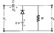
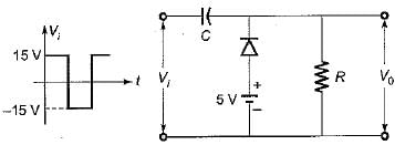
For the network shown below, the input swing of 30 volts is equal to the
Detailed Solution for Test: Diode Circuits- 2 - Question 1

• During the negative half cycle of input voltage Vi, diode is forward biased and acts as short-circuit. Hence capacitor changes to VC volts.

Using KVL,
-5 + VC - 15 = 0
or,  VC - 20 volts
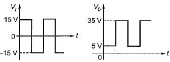
Hence, V0 = 5 volts
• During the positive half cycle of input voltage Vi, diode is reverse biased and acts as open-circuit.
Applying KVL, we have
15 = -20 + \/0
or V0 = 35 volts
The waveforms for Vi and V0 will be as shown below:

Thus, the input swing of 30 V is equal to the output swing of 30 V.

Test: Diode Circuits- 2 - Question 2

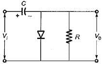
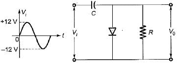
The output voltage V0 for the circuit shown below for the given sinusoidal input signal will be represented as
Detailed Solution for Test: Diode Circuits- 2 - Question 2

• When Vi is positive:
Diode is ON and acts as short circuit. Output voltage,
V0 = 0V
The capacitor charges to 12 volts as shown below and acts like a battery.

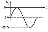
• When Vi is negative:
Diode is OFF and acts as open circuit. Output voltage,
V0 = -12-12 = -24 Volt
This gives negatively clamped voltage and the resultant output waveform will be as shown in figure below.

1 Crore+ students have signed up on EduRev. Have you? Download the App
Test: Diode Circuits- 2 - Question 3

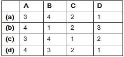
Match List-I (Circuits) with List-II (Applications) and select the correct answer using the codes given below the lists:
List-I
A. Diode comparators
B. Diode dampers
C. Astable multivibrator
D. Diode clippers
List-II
1. Slicer
2. Oscillator
3. DC level to an AC signal
4. Square wave from a sine wave
Test: Diode Circuits- 2 - Question 4

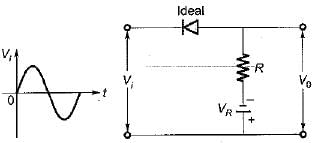
The circuit shown below represents a

Detailed Solution for Test: Diode Circuits- 2 - Question 4

• WhenVi is positive:
Diode is OFF so that, V0 = -VR
• When Vi is negative:
 Diode is OFF so that,.
 Diode is ON so that,
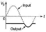
Hence, output waveform will be as shown below.

Test: Diode Circuits- 2 - Question 5

Assertion (A): Clipping circuit controls the shape of the waveform by clipping or removing a portion of the applied wave.
Reason (R): It needs minimum three components namely an ordinary diode, a resistor and a capacitor.

Detailed Solution for Test: Diode Circuits- 2 - Question 5

A clamper circuit requires a capacitor not a clipping circuit. Hence, reason is not a correct statement.

Test: Diode Circuits- 2 - Question 6

Consider the following statements associated with the diode rectifier circuits:
1. The maximum reverse voltage, which can be applied before the breakdown point is reached, is called the “peak inverse voltage”.
2. In a full-wave rectifier, the current in each of the diode flows for the whole input signal cycle.
3. The ratio of direct or average value of the output to the effective value of AC component present in the rectifier output is called the “ripple factor”.
4. Availability of low-cost silicon diodes has made bridge circuit arrangement more economical than centre trapped transformer arrangement despite its requirement of four diodes:

Q. Which of the above statements are correct?

Detailed Solution for Test: Diode Circuits- 2 - Question 6

• In a full-wave rectifier each diode conducts during one half-cycle. Hence, statement-2 is not correct.
• Ripple factor is the ratio of rms value of AC component to the DC component in the output.

Hence, statement - 3 is also not correct.

Test: Diode Circuits- 2 - Question 7

In the Zener regulator shown below, the output requirements are 5 V, 20 mA. Iz(min) and Iz(max) are 5 mA and 80 mA, then the value of limiting resistor (R) and the load resistance (RL) will be respectively

Detailed Solution for Test: Diode Circuits- 2 - Question 7

Given, minimum Zener current = Iz(min) = 5 mA when the input voltage is minimum.
Here, the input voltage varies between 8 V to 12V.

Given, lL = 20 mA and voltage across load,
V0 = 5 volts
∴ 
∴ Limiting resistance,

Test: Diode Circuits- 2 - Question 8

For the zener voltage regular circuit shown below, the output voltage is required to be maintained at 5 volt with a load current of 10 mA. The zener wattage is 400 mW and input voltage is specified as 10 V ± 2 V.
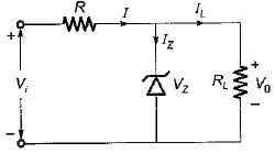
One of the possible value of series resistance R will be

Detailed Solution for Test: Diode Circuits- 2 - Question 8

Given, V0 = 5 V, IL = 10 mA
Load resistance,

Maximum Zener current,

(Since Pz(max) = 400 mW)
The minimum input voltage required will be when 
Under this condition,
I = IL = 10 mA
Minimum input voltage,
Vi(min) = V0 +IR    ...(i)
Given, Vi = 10 V ± 2 V

From equations (i) and (ii), we have
8 = 5 + (10 x 10-3) R
or, 
Now, maximum input voltage,

or 12 = 5 + (90 x 10-3) R
or, 
Hence, 77.77 Ω < R < 300 Ω
Thus, one of the possible value of out of the given options is R = 266 Ω

Test: Diode Circuits- 2 - Question 9

The Zener diode VZ1 in the figure shown below has the reverse saturation current of 20 mA and reverse breakdown voltage of 100 V whereas the corresponding values for diode  VZ2  are 40 μA and 40 V.
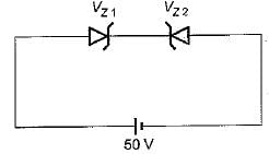
The current through the circuit is

Detailed Solution for Test: Diode Circuits- 2 - Question 9

The Zener diode VZ2 is reverse biased and VZ1 is forward biased. As both Zener diodes \/Z1 and VZ2 are connected in series, the reverse saturation current 40 μA of VZ2 will flow clockwise in the circuit as 50 V reverse bias appears across the VZ2 diode.

Test: Diode Circuits- 2 - Question 10

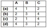
Match List-I (Diode Circuits) with List-ll (Output-Input Characteristics) and select the correct answer using the codes given below the lists:
List-I
A. 
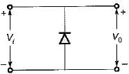
B. 
C. 
List-II
1. 
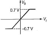
2.
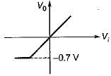
3. 
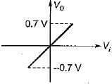
4.
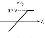
Codes:
Test: Diode Circuits- 2 - Question 11

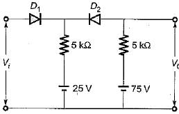
What is the output voltage of clipper circuit shown in figure below for the sinusoidal input voltage with its peak voltage of 100 V, assuming both diodes ideal?
Detailed Solution for Test: Diode Circuits- 2 - Question 11

For, V< 25 volts,
Diode D1 will be OFF while diode D2 will be ON.
∴ 

Test: Diode Circuits- 2 - Question 12

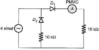
For the circuit shown below, assume that the diodes are ideal. The meter reading would be
Detailed Solution for Test: Diode Circuits- 2 - Question 12

The PMMC ammeter will read average value of current. The current through the PMMC ammeter will flow only for positive half cycle of input voltage while current through it will be zero for the negative half cycle.
Hence,


∴ 

Test: Diode Circuits- 2 - Question 13

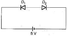
Two identical diodes, D1 and D2 are connected back to back as shown in figure below. The reverse saturation current I0 of each diode is 10-8 A and the breakdown voltage is 50 V. The voltage drop across diodes D1 and D2 will be respectively (assume kTlq = 25 mV)
Detailed Solution for Test: Diode Circuits- 2 - Question 13

Diode D1 is reverse biased and diode D2 is forward biased, but as both the diodes form a close loop, the reverse saturation current flows through both the diodes.

or, 
or, V2 = VTln 2 = (25 mV) x In 2
= 25 x10-3 x 0 .693
= 17.33 mV = 0.01733 V
∴ Voltage drop across D2 is
v2 ≈ 0.0173 volt
and voltage drop across D1 is
V1 ≈ 5 - 0.0173 ≈ 4.983 volts

Test: Diode Circuits- 2 - Question 14

The 6 V Zener diode shown in figure has zero zener resistance and a knee current of 5 mA.
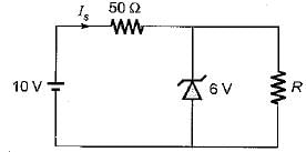
The minimum value of R so that the voltage across it does not fall below 6 V is 

Detailed Solution for Test: Diode Circuits- 2 - Question 14


The maximum load current = 80 - 5 = 75 mA
Hence, minimum load resistance

Test: Diode Circuits- 2 - Question 15

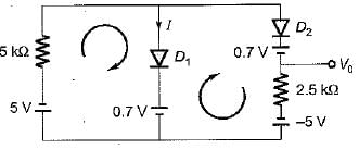
What are the values of V0 and I for the diode circuit shown below?
(Assume the drop across the diodes to be 0.7 V)
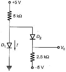
 

Detailed Solution for Test: Diode Circuits- 2 - Question 15

If the diode D1 conducts, the current I must flow as indicated in figure below.
Here,


Since, I is negative, therefore D1 does not conduct.
∴ 

Test: Diode Circuits- 2 - Question 16

A DC power supply has no-load voltage of 30 V, and a full-load voltage of 25 V at a full-load current of 1 A. Its output resistance and load regulation, respectively, are

Detailed Solution for Test: Diode Circuits- 2 - Question 16


Output resistance = 

Test: Diode Circuits- 2 - Question 17

Higher order active filters are used for variable

Detailed Solution for Test: Diode Circuits- 2 - Question 17

Higher order active filters are used for variable roll-off rate.

Test: Diode Circuits- 2 - Question 18

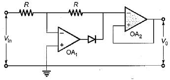
In the figure shown below, the diode of Op-amps are ideal. For an input Vin = sin (ωt) the output voltages V0 is
Test: Diode Circuits- 2 - Question 19

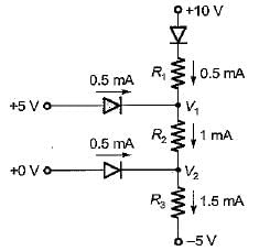
The cutin voltage for each diode in figure is Vγ = 0.6 V. Each diode current is 0.5 mA. The value of R1 R2 and R3 will be respectively
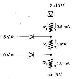
Detailed Solution for Test: Diode Circuits- 2 - Question 19


(∵ V2 = 4.4 - 5 = - 0.6 volt)

Test: Diode Circuits- 2 - Question 20

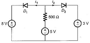
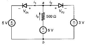
In the circuit shown below, diodes D1 and D2 are ideal. The current i1 and i2 are respectively​

Detailed Solution for Test: Diode Circuits- 2 - Question 20


For i3 > 0, Vab < 5 volts and VD1 < 0
Hence, i = 0
and 

212 tests
Information about Test: Diode Circuits- 2 Page
In this test you can find the Exam questions for Test: Diode Circuits- 2 solved & explained in the simplest way possible. Besides giving Questions and answers for Test: Diode Circuits- 2, EduRev gives you an ample number of Online tests for practice

Top Courses for Electrical Engineering (EE)

Download as PDF

Top Courses for Electrical Engineering (EE)