Electrical Engineering (EE) Exam  >  Electrical Engineering (EE) Tests  >  Engineering Services Examination (ESE) Mock Test Series 2024  >  Test: ESE Electrical - 8 - Electrical Engineering (EE) MCQ

Test: ESE Electrical - 8 - Electrical Engineering (EE) MCQ


Test Description

30 Questions MCQ Test Engineering Services Examination (ESE) Mock Test Series 2024 - Test: ESE Electrical - 8

Test: ESE Electrical - 8 for Electrical Engineering (EE) 2024 is part of Engineering Services Examination (ESE) Mock Test Series 2024 preparation. The Test: ESE Electrical - 8 questions and answers have been prepared according to the Electrical Engineering (EE) exam syllabus.The Test: ESE Electrical - 8 MCQs are made for Electrical Engineering (EE) 2024 Exam. Find important definitions, questions, notes, meanings, examples, exercises, MCQs and online tests for Test: ESE Electrical - 8 below.
Solutions of Test: ESE Electrical - 8 questions in English are available as part of our Engineering Services Examination (ESE) Mock Test Series 2024 for Electrical Engineering (EE) & Test: ESE Electrical - 8 solutions in Hindi for Engineering Services Examination (ESE) Mock Test Series 2024 course. Download more important topics, notes, lectures and mock test series for Electrical Engineering (EE) Exam by signing up for free. Attempt Test: ESE Electrical - 8 | 150 questions in 180 minutes | Mock test for Electrical Engineering (EE) preparation | Free important questions MCQ to study Engineering Services Examination (ESE) Mock Test Series 2024 for Electrical Engineering (EE) Exam | Download free PDF with solutions
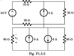
Test: ESE Electrical - 8 - Question 1

v1 = ?

Detailed Solution for Test: ESE Electrical - 8 - Question 1

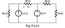
Test: ESE Electrical - 8 - Question 2

v2 = ?

Detailed Solution for Test: ESE Electrical - 8 - Question 2

1 Crore+ students have signed up on EduRev. Have you? Download the App
Test: ESE Electrical - 8 - Question 3

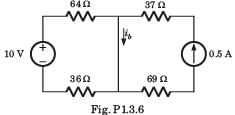
ib = ?

Detailed Solution for Test: ESE Electrical - 8 - Question 3

Correct Answer :- B
Current due to voltage source is:

I' = 10/(64+36) 

= 0.1A.

Current due to current source is:

I = 0.5A.

Current ib = I' + I 

= 0.5+ 0.1

= 0.6A

Test: ESE Electrical - 8 - Question 4

 The current and voltage profile of an element vs time has been shown in given figure. The element and its value are respectively:

Detailed Solution for Test: ESE Electrical - 8 - Question 4
  • Since V is not proportional to R therefore, the element can’t be a resistor.
  • At t = 5 ms, even if i ≠ 0, the element behaves as a short circuit therefore, the element can’t be a capacitor (since at t = 0 only capacitor behaves as short circuit).
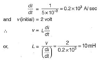
  • The current at t = 0 is zero and at t = 5 ms voltage across the element is zero therefore, the element must be an inductor (at t = 0, an inductor acts as open circuit and at t =∞ it behaves as short circuit).
  • From the given voltage and current profile, we have:
Test: ESE Electrical - 8 - Question 5

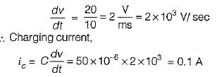
 Figure shown below exhibits the voltage-time profile of a source to charge a capacitor of 50 μF. The value of charging current in amperes is:

Detailed Solution for Test: ESE Electrical - 8 - Question 5

From given figure:

Test: ESE Electrical - 8 - Question 6

 The equivalent capacitance across the given terminals A-B is:
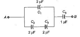
Detailed Solution for Test: ESE Electrical - 8 - Question 6
  • The equivalent combination of C2 and C3
  • The equivalent combination of this 1 μF and  C1 = 2μF is C1+ 1 μF = 3μF
  • Hence, the equivalent capacitance between terminals A and B is
Test: ESE Electrical - 8 - Question 7

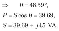
Determine the complex power for hte given values in question.

S = 60 VA, Q = 45 VAR (inductive)

Detailed Solution for Test: ESE Electrical - 8 - Question 7

Q = S sin θ 
⇒ 

Test: ESE Electrical - 8 - Question 8

Which among the following is regarded as short circuit forward transfer admittance?

Detailed Solution for Test: ESE Electrical - 8 - Question 8

In a two-port network, the short-circuit forward transfer admittance represents the relationship between the input current and the output voltage when the output port is short-circuited. It is denoted as y21.

The different parameters denoted by y in a two-port network are:

  • y11: Input admittance with the output port open (Short-circuit reverse transfer admittance)
  • y12: Forward transfer admittance with the input port open (Open-circuit reverse transfer admittance)
  • y21: Forward transfer admittance with the output port short-circuited (Short-circuit forward transfer admittance)
  • y22: Output admittance with the input port open (Open-circuit forward transfer admittance)

Among these parameters, the short-circuit forward transfer admittance is represented by y21.

Therefore, the correct answer is C: y21.

Test: ESE Electrical - 8 - Question 9

If the load impedance is Z∠Ø, the expression obtained for current (IB) is?

Detailed Solution for Test: ESE Electrical - 8 - Question 9

As the load impedance is Z∠Ø, the current flows in the three load impedances and the current flowing in the B impedance is IB = VBR∠240⁰/Z∠Ø = (V/Z)∠-240-Ø.

Test: ESE Electrical - 8 - Question 10

The three impedances Z1 = 20∠30⁰Ω, Z2 = 40∠60⁰Ω, Z3 = 10∠-90⁰Ω are delta-connected to a 400V, 3 – Ø system. Find the line current I2.

Detailed Solution for Test: ESE Electrical - 8 - Question 10

The line current I2 is the difference of IY and IR. So the line current I2 is I2 = IY – IR = (-27.32 + j10) A.

Test: ESE Electrical - 8 - Question 11

The force on a conductor of length 12cm having current 8A and flux density 3.75 units at an angle of 300 is

Detailed Solution for Test: ESE Electrical - 8 - Question 11

To calculate the force on a conductor in a magnetic field, we can use the formula:

Force (F) = I * L * B * sin(theta)

Where:

  • I is the current flowing through the conductor
  • L is the length of the conductor
  • B is the magnetic flux density
  • theta is the angle between the direction of the current and the magnetic field

In this case, the given values are:

  • I = 8A
  • L = 12cm = 0.12m
  • B = 3.75 units
  • theta = 30 degrees = 30 * (pi/180) radians = pi/6 radians

Plugging in these values into the formula:

F = 8 x 0.12 x  3.75 x  sin(pi/6)

Using a calculator, we can find:

F ≈ 1.8 units

Therefore, the correct answer is D: 1.8.

Test: ESE Electrical - 8 - Question 12

The force per unit length of two conductors carrying equal currents of 5A separated by a distance of 20cm in air(in 10-6 order) 

Detailed Solution for Test: ESE Electrical - 8 - Question 12

The force per unit length of two conductors is given by
F = μ I1xI2/2πD, where I1 = I2 = 5 and D = 0.2. Thus F = 4π x 10-7 x 52/ 2π x 0.2 = 25 x 10-6 units.

Test: ESE Electrical - 8 - Question 13

The impulse response of a causal, linear, time- invariant, continuous time system is h(t). The output y(t) of the same system to an input x(t). Where x(t) = 0 for t < -2 is

Detailed Solution for Test: ESE Electrical - 8 - Question 13

Since, causal system

h(t) = 0 for t < 0

Input y(t) = x(t) * h(t)

h(τ) = 0 for τ < 0

x ( t - τ) = 0, for t - τ < - 2

∴ τ > f + 2

Test: ESE Electrical - 8 - Question 14

Which of the following has to be performed in sampling rate conversion by rational factor?

Detailed Solution for Test: ESE Electrical - 8 - Question 14

Sampling rate conversion by a rational factor involves changing the sampling rate of a signal by a non-integer ratio. This process requires both interpolation and decimation, but specifically, interpolation is necessary in this case.

Interpolation is the process of increasing the sampling rate by inserting additional samples between existing samples. It involves creating new samples that approximate the values of the original signal at higher frequencies. Interpolation helps in achieving a higher sampling rate while preserving the signal's characteristics.

Decimation, on the other hand, is the process of decreasing the sampling rate by discarding some samples. It involves reducing the number of samples in a signal while maintaining the important information and characteristics of the signal.

In sampling rate conversion by a rational factor, interpolation is required to generate additional samples to match the desired higher sampling rate. After interpolation, decimation can be performed if necessary to achieve the final desired sampling rate.

Therefore, the correct answer is A: Interpolation.

Test: ESE Electrical - 8 - Question 15

Which of the following operation is performed by the blocks given the figure below?

Detailed Solution for Test: ESE Electrical - 8 - Question 15

In the diagram given, a interpolator is in cascade with a decimator which together performs the action of sampling rate conversion by a factor I/D.

Test: ESE Electrical - 8 - Question 16

Determine the time signal x(t) corresponding to given X (s) and choose correct option.
Q. 

Detailed Solution for Test: ESE Electrical - 8 - Question 16


x(t) = ( e-t - 2te-2t) u(t)

Test: ESE Electrical - 8 - Question 17

Determine the time signal x(t) corresponding to given X (s) and choose correct option.
Q. 

Detailed Solution for Test: ESE Electrical - 8 - Question 17


Test: ESE Electrical - 8 - Question 18

Determine the Fourier series coefficient for given periodic signal x(t).
Q. x(t) as shown in fig. P5.7.1
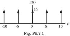
Detailed Solution for Test: ESE Electrical - 8 - Question 18


A = 10 , T =  5, X [k] =  2

Test: ESE Electrical - 8 - Question 19

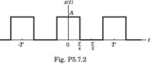
Determine the Fourier series coefficient for given periodic signal x(t).
Q. x(t) as shown in fig. P5.7.2
Detailed Solution for Test: ESE Electrical - 8 - Question 19


Test: ESE Electrical - 8 - Question 20

In the question, the FS coefficient of time-domain signal have been given. Determine the corresponding time domain signal and choose correct option.

Que: X[k] As shown in fig. , ωo = π

Detailed Solution for Test: ESE Electrical - 8 - Question 20

Test: ESE Electrical - 8 - Question 21

A band-limited signal with a maximum frequency of 5 kHz is to be sampled. According to the sampling theorem, the sampling frequency which is not valid is

Detailed Solution for Test: ESE Electrical - 8 - Question 21

The maximum frequency of the band-limited signal.
fm = 5 kHz
According to the Nyquist sampling theorem, the sampling frequency must be greater than the Nyquist  frequency which is given as
fN = 2 fm = 2 × 5 = 10 kHz
So the sampling frequency fs ≥ fN
fs ≥ 10 kHz
Only the option (A) does not satisfy the condition.
∴ 5 kHz is not a valid sampling frequency.

Test: ESE Electrical - 8 - Question 22

 The total number of complex multiplications required to compute N point DFT by radix-2 FFT is: 

Detailed Solution for Test: ESE Electrical - 8 - Question 22

The decimation of the data sequence should be repeated again and again until the resulting sequences are reduced to one point sequences. For N=2v, this decimation can be performed v=log2N times. Thus the total number of complex multiplications is reduced to (N/2)log2N.

Test: ESE Electrical - 8 - Question 23

The realization of FIR filter by frequency sampling realization can be viewed as cascade of how many filters?

Detailed Solution for Test: ESE Electrical - 8 - Question 23
  • In frequency sampling realization, the system function H(z) is characterized by the set of frequency samples {H(k+ α)} instead of {h(n)}.
  • We view this FIR filter realization as a cascade of two filters. One is an all-zero or a comb filter and the other consists of parallel bank of single pole filters with resonant frequencies.
Test: ESE Electrical - 8 - Question 24

Which of the following is a frequency domain specification?

Detailed Solution for Test: ESE Electrical - 8 - Question 24
  • We are required to design a low pass Butterworth filter to meet the following frequency domain specifications.
  • KP ≤ 20 log|H(jΩ)| ≤ 0 and 20 log|H(jΩ)| ≤ KS.
Test: ESE Electrical - 8 - Question 25

Assertion (A): Closed loop control systems are known as feedback control systems.
Reason (R): In closed loop control systems, the control action is dependent on the desired output.

Detailed Solution for Test: ESE Electrical - 8 - Question 25
  • In closed loop system there is the presence of a feedback path and this feedback path has connected from output of the system to the input of the system.
  • The whole operation is controlled by the output of the system.
Test: ESE Electrical - 8 - Question 26

The relationship between an input and output variable of a signal flow graph is given by the net gain between the input and output node is known as the overall______________

Detailed Solution for Test: ESE Electrical - 8 - Question 26

In a signal flow graph, the net gain between the input and output node represents the relationship between an input variable and an output variable. This net gain is calculated by multiplying the individual gains along the paths from the input node to the output node.

The overall gain of the system refers to the cumulative effect of these individual gains on the input-output relationship. It represents the ratio of the output variable to the input variable, taking into account all the intermediate gains in the signal flow graph.

Therefore, the correct answer is A: Overall gain of the system.

Test: ESE Electrical - 8 - Question 27

The damping ratio of a system having the characteristic equation s2 + 2s + 8 = 0 is

Detailed Solution for Test: ESE Electrical - 8 - Question 27

Given, s2 + 2s + 8 = 0
Here, ωn = √8 rad/s = 2√2 rad/sec

system is underdamped.

Test: ESE Electrical - 8 - Question 28

What is the range of values of K (K > 0) such that the characteristic equation
s3 + 3 (K + 1)s2 + (7K + 5)s + (4K + 7) = 0
has roots more negative than s = -1?

Detailed Solution for Test: ESE Electrical - 8 - Question 28

Putting s = (z - 1) in the given characteristic equation, we get:
(z - 1)3 + 3 (K + 1) (z - 1)2 + (7K+ 5) (z - 1) + (4K + 7) = 0
or, z3 + 3 Kz2 + (K + 2)z + 4 = 0
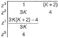
Routh’s array is:


i.e. 3K2 + 6K - 4 > 0 and K > 0
Now, roots of 3K2 + 6K - 4 = 0 are: K = -2.5, 0.53
Since K > 0 ∴ K = 0.53 (K = -2.5 neglected)
For K > 0.53, 3 K2 + 6 K - 4 > 0
Hence, the range of value of K is
0.53 < K < ∞ or ∞ > K > 0.53

Test: ESE Electrical - 8 - Question 29

The breakaway point in the root loci plot for the loop transfer function

Detailed Solution for Test: ESE Electrical - 8 - Question 29

Given, 

1+ G(s) = 0
or, s (s2+ 6 s + 12) + K = 0
or, K = - (s3 + 6s2 + 12s)
For B.A. points, 

or, s2 + 4s + 4 = 0
or, (s + 2)2 = 0
or, s = - 2 , - 2
For given O.L.T.F., P = 3, Z = 0, P - Z = 3

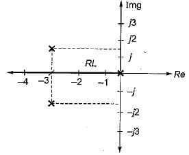
Poles are at s = 0 and s = -3 ± j√3 = -3 ± j1.732
Since entire -ve real axis is a part of root locus, therefore s = -2 is a valid breakaway point.

Test: ESE Electrical - 8 - Question 30

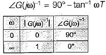
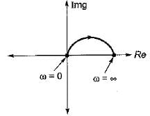
The inverse polar plot of the open loop transfer function, G(s) = (1+sT)/(sT) will be re presented by

Detailed Solution for Test: ESE Electrical - 8 - Question 30

Given, G(s) = (1+sT)/(sT)
The inverse polar plot of G(jω) is the polar plot of 1/G(jω)

Thus, 

and

Hence, inverse polar plot will be as show below,

View more questions
12 tests
Information about Test: ESE Electrical - 8 Page
In this test you can find the Exam questions for Test: ESE Electrical - 8 solved & explained in the simplest way possible. Besides giving Questions and answers for Test: ESE Electrical - 8, EduRev gives you an ample number of Online tests for practice

Top Courses for Electrical Engineering (EE)

Download as PDF

Top Courses for Electrical Engineering (EE)