Electrical Engineering (EE) Exam  >  Electrical Engineering (EE) Tests  >  SSC JE Electrical Mock Test Series 2025  >  Test: Electrical Circuits- 1 - Electrical Engineering (EE) MCQ

Test: Electrical Circuits- 1 - Electrical Engineering (EE) MCQ


Test Description

20 Questions MCQ Test SSC JE Electrical Mock Test Series 2025 - Test: Electrical Circuits- 1

Test: Electrical Circuits- 1 for Electrical Engineering (EE) 2024 is part of SSC JE Electrical Mock Test Series 2025 preparation. The Test: Electrical Circuits- 1 questions and answers have been prepared according to the Electrical Engineering (EE) exam syllabus.The Test: Electrical Circuits- 1 MCQs are made for Electrical Engineering (EE) 2024 Exam. Find important definitions, questions, notes, meanings, examples, exercises, MCQs and online tests for Test: Electrical Circuits- 1 below.
Solutions of Test: Electrical Circuits- 1 questions in English are available as part of our SSC JE Electrical Mock Test Series 2025 for Electrical Engineering (EE) & Test: Electrical Circuits- 1 solutions in Hindi for SSC JE Electrical Mock Test Series 2025 course. Download more important topics, notes, lectures and mock test series for Electrical Engineering (EE) Exam by signing up for free. Attempt Test: Electrical Circuits- 1 | 20 questions in 12 minutes | Mock test for Electrical Engineering (EE) preparation | Free important questions MCQ to study SSC JE Electrical Mock Test Series 2025 for Electrical Engineering (EE) Exam | Download free PDF with solutions
Test: Electrical Circuits- 1 - Question 1

Three wires having conductance’s 2, 3 and 6 mho respectively are connected in parallel in a circuit. The equivalent resistance in the circuit will be:

Detailed Solution for Test: Electrical Circuits- 1 - Question 1

Given that,

G1 = 2 mho

G2 = 3 mho

G3 = 6 mho

These are connected in parallel.

Geq = G1 + G2 + G3 + …… + Gn

⇒ Geq = 2 + 3 + 6 = 11 mho

Test: Electrical Circuits- 1 - Question 2

What is the difference between an atom and an ion?

Detailed Solution for Test: Electrical Circuits- 1 - Question 2

An ion is a particle or collection of particles with a net positive or negative charge.

An atom is the basic unit of an element. The identity of an element is determined by the number of positively charged protons in the atom’s nucleus. A stable atom contains the same number of electrons as protons and no net charge.

1 Crore+ students have signed up on EduRev. Have you? Download the App
Test: Electrical Circuits- 1 - Question 3

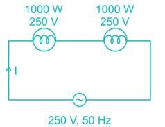
Two heaters rated at 1000 W, 250V each are connected in series across a 250 V, 50 Hz ac mains. The total power drawn from the supply would be _____ watt.

Detailed Solution for Test: Electrical Circuits- 1 - Question 3


Total power drawn from the supply

P = VI = 250 × 2 = 500 W.

Test: Electrical Circuits- 1 - Question 4

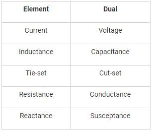
Which of the following does not have dual relationship?

Detailed Solution for Test: Electrical Circuits- 1 - Question 4

Test: Electrical Circuits- 1 - Question 5

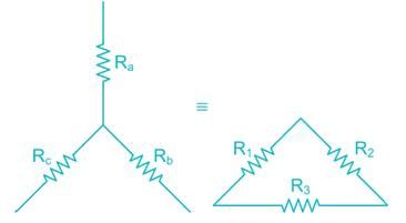
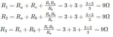
If each branch of star connection is 3 Ω. Then its corresponding delta connection will contain ______.

Detailed Solution for Test: Electrical Circuits- 1 - Question 5


Test: Electrical Circuits- 1 - Question 6

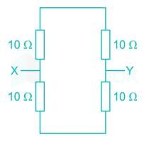
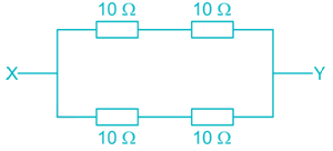
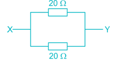
Find out resistance between X and Y in following:

Detailed Solution for Test: Electrical Circuits- 1 - Question 6


Test: Electrical Circuits- 1 - Question 7

In a four-branch parallel circuit, there are 10 mA of current in each branch. If one of the branches is open, the current in each of the other three branches is:

Detailed Solution for Test: Electrical Circuits- 1 - Question 7

All the four branches are connected in parallel, so the voltage across every branch is same. If one of the branch is open, it doesn’t affect the other branches current. Because the voltage and impedance across remaining branches will remain same.

Test: Electrical Circuits- 1 - Question 8

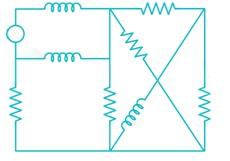
The number of mesh currents required in the circuit given below is:
Detailed Solution for Test: Electrical Circuits- 1 - Question 8

In the given network

Number of branches (b) = 9

Number of nodes (n) = 5

Number of mesh currents = b – n + 1

= 9 – 5 + 1 = 5

Test: Electrical Circuits- 1 - Question 9

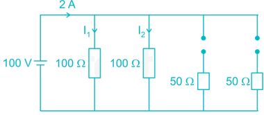
Four resistors of 50 Ω, 50 Ω, 100 Ω and 100 Ω each are connected in parallel across 100 V dc supply. What is the current though each branch if both the resistors of 50 Ω burn out?

Detailed Solution for Test: Electrical Circuits- 1 - Question 9

Current flowing through 100 Ω resistance,

Test: Electrical Circuits- 1 - Question 10

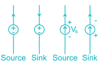
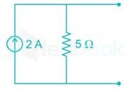
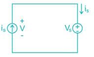
A current source and a voltage source are connected in parallel as shown below. Suppose that vs = 12 V and is = 3 A.What is the power supplied by each source?
Detailed Solution for Test: Electrical Circuits- 1 - Question 10

Power supplied by current source = 12 × 3 = 36 W

Here current source acts as source

Power supplied by voltage source = 12 × (-3) = -36W

Here voltage source acts as sink.

Test: Electrical Circuits- 1 - Question 11

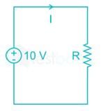
A voltage source of 10 V and resistor are connected in series. Specify the resistance R so that both of the following conditions are satisfied:

i > 40 mA and the power absorbed by the resistors is < 0.5 W.

Detailed Solution for Test: Electrical Circuits- 1 - Question 11

Given that,

I > 40 mA


⇒ R > 200

⇒ 200 < R < 250

Test: Electrical Circuits- 1 - Question 12

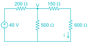
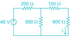
Determine the value of the current i for the circuit shown below.
Detailed Solution for Test: Electrical Circuits- 1 - Question 12

Apply nodal analysis at node v.

⇒ 25V = 600

⇒ v = 24

Test: Electrical Circuits- 1 - Question 13

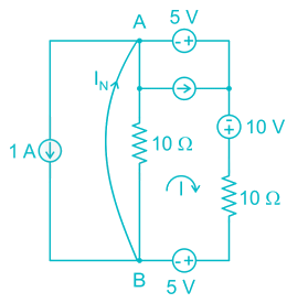
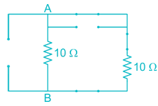
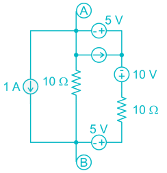
An equivalent single current source between ‘A’ and ‘B’ in the following figure will be:
Detailed Solution for Test: Electrical Circuits- 1 - Question 13

An equivalent single current source is nothing but Norton’s equivalent

To find short circuit current (IN)

Apply kVL

-5 – 10 + 10 I + 5 = 0

⇒ I = 1A

Apply kCL at point B,

IN = 1 + 1 = 2A

To find Norton’s resistance, we need to short circuit the voltage sources and open circuit the current sources.

RAB = (10 || 10) = 5Ω

Test: Electrical Circuits- 1 - Question 14

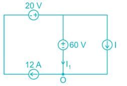
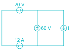
In the interconnection of ideal sources shown in the following figure, it is known that the 60 V source is absorbing power. Which of the following can be the value of the current source i?
Detailed Solution for Test: Electrical Circuits- 1 - Question 14

kCL at O

⇒ I1 + I = 12

⇒ I = 12 – I1

By the above equation,

I should be less than 12 A.

Hence 10 A can be the value of the current source I.

Test: Electrical Circuits- 1 - Question 15

The capacitor voltage in the circuit long after the switch has been closed is:
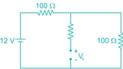
Detailed Solution for Test: Electrical Circuits- 1 - Question 15

After t = 0, at steady state

Test: Electrical Circuits- 1 - Question 16

A sinusoidal current is given as i(t) = 150 cos (1000πt – 45°)mA. Determine the period T and time t2 at which the first positive peak occurs:

Detailed Solution for Test: Electrical Circuits- 1 - Question 16

i(t) = 150 cos (1000 πt – 45°) mA

i(t) can attain max at

1000πt - π/4 = 0

Test: Electrical Circuits- 1 - Question 17

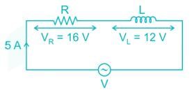
In a series RL circuit 5 A current is flowing, voltage drop across R is 16 V and voltage drop across L is 12 V calculate impedance –

Detailed Solution for Test: Electrical Circuits- 1 - Question 17


⇒ z = 4 ∠36 - 9°

Test: Electrical Circuits- 1 - Question 18

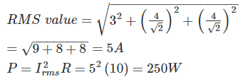
The current i(t), through a 10 Ω resistor in series with an inductance is given by I(t) = 3 + 4 sin(100t + 450) + 4sin(300t + 600) amperes the RMS values of the current and power dissipation in the circuit are

Detailed Solution for Test: Electrical Circuits- 1 - Question 18

Test: Electrical Circuits- 1 - Question 19

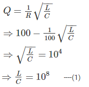
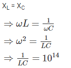
A series RLC circuit has Q of 100 and an impendence of (100 ± j0)Ω at its resonant angular frequency of 107 rad/s. The value of R and L respectively –

Detailed Solution for Test: Electrical Circuits- 1 - Question 19

ω = 107 rad/s

Q = 100

R = 100 Ω

for resonance condition,

⇒ LC = 10-14      ----(2)

By (1) and (2)

⇒ L = 10-3 H

Test: Electrical Circuits- 1 - Question 20

What will be the average value of the sawtooth waveform shown below?
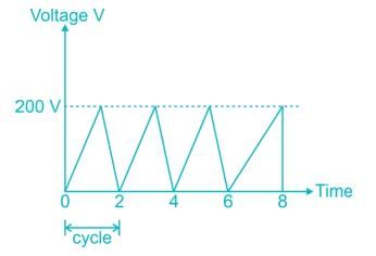
Detailed Solution for Test: Electrical Circuits- 1 - Question 20

2 videos|1 docs|55 tests
Information about Test: Electrical Circuits- 1 Page
In this test you can find the Exam questions for Test: Electrical Circuits- 1 solved & explained in the simplest way possible. Besides giving Questions and answers for Test: Electrical Circuits- 1, EduRev gives you an ample number of Online tests for practice

Top Courses for Electrical Engineering (EE)

Download as PDF

Top Courses for Electrical Engineering (EE)