Electrical Engineering (EE) Exam  >  Electrical Engineering (EE) Tests  >  SSC JE Electrical Mock Test Series 2025  >  Test: Electrical Circuits- 3 - Electrical Engineering (EE) MCQ

Test: Electrical Circuits- 3 - Electrical Engineering (EE) MCQ


Test Description

20 Questions MCQ Test SSC JE Electrical Mock Test Series 2025 - Test: Electrical Circuits- 3

Test: Electrical Circuits- 3 for Electrical Engineering (EE) 2024 is part of SSC JE Electrical Mock Test Series 2025 preparation. The Test: Electrical Circuits- 3 questions and answers have been prepared according to the Electrical Engineering (EE) exam syllabus.The Test: Electrical Circuits- 3 MCQs are made for Electrical Engineering (EE) 2024 Exam. Find important definitions, questions, notes, meanings, examples, exercises, MCQs and online tests for Test: Electrical Circuits- 3 below.
Solutions of Test: Electrical Circuits- 3 questions in English are available as part of our SSC JE Electrical Mock Test Series 2025 for Electrical Engineering (EE) & Test: Electrical Circuits- 3 solutions in Hindi for SSC JE Electrical Mock Test Series 2025 course. Download more important topics, notes, lectures and mock test series for Electrical Engineering (EE) Exam by signing up for free. Attempt Test: Electrical Circuits- 3 | 20 questions in 12 minutes | Mock test for Electrical Engineering (EE) preparation | Free important questions MCQ to study SSC JE Electrical Mock Test Series 2025 for Electrical Engineering (EE) Exam | Download free PDF with solutions
Test: Electrical Circuits- 3 - Question 1

If the length of a wire having uniform resistance R is stretched in m times with volume remaining same. What will be new resistance value?

Detailed Solution for Test: Electrical Circuits- 3 - Question 1

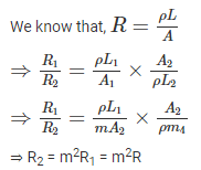
Given that, the length of a wire having uniform resistance R is stretched in m times with volume remaining same.

Let the length of the wire is L1

and the area of the wire is A1

For volume remains to be same

L1A1 = L2A2

⇒ L11 = (mL1) (A2)

⇒ A1 = mA2

Test: Electrical Circuits- 3 - Question 2

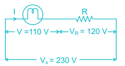
A filament lamp of 40 W, 110 V is connected in series with resistance R. if the supply voltage is 230 V, the value of resistance R should be:

Detailed Solution for Test: Electrical Circuits- 3 - Question 2

Given that, P = 40 W, V = 110 V

Voltage across resistor = Vs - V = 230 - 110 = 120 V

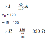
Power rating of lamp = 40

⇒ VI = 40


1 Crore+ students have signed up on EduRev. Have you? Download the App
Test: Electrical Circuits- 3 - Question 3

The temperature coefficient of resistance of material is given as:


Detailed Solution for Test: Electrical Circuits- 3 - Question 3

We know that, R = R0[1+α(T1−T2)]

Where α is a temperature coefficient of resistance

If the temperature coefficient of resistance is positive, it indicates that the resistance increases with the increase in temperature

If the temperature coefficient of resistance is negative, it indicates that the resistance decreases with the increase in temperature

Test: Electrical Circuits- 3 - Question 4

Which of the following is not the same as watt?

Detailed Solution for Test: Electrical Circuits- 3 - Question 4

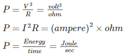
Watt is the unit of power. We can represent the power as follows

Hence Volt/Ampere is not same as watt, it is equal to ohm.

Test: Electrical Circuits- 3 - Question 5

Find the average current flow in the wire.

Given: type of wire: metallic

Total electrons drift across section per second = 1020

Detailed Solution for Test: Electrical Circuits- 3 - Question 5

Total electrons drift across section power second = 1020

We know that, q = it

For t = 1 sec

⇒ q = i

⇒ i = q = ne = 1020 × 1.6 × 10-19 = 16 A

Test: Electrical Circuits- 3 - Question 6

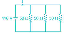
Three equal resistors of 50 Ω each are connected in parallel across 110 V dc supply. What is the current through each branch if one of the resistors gets shorted?

Detailed Solution for Test: Electrical Circuits- 3 - Question 6

If one of the resistors gest shorted, remaining two resistors also gets shorted as they are connected in parallel. Hence the current flow through each branch will be zero.

Test: Electrical Circuits- 3 - Question 7

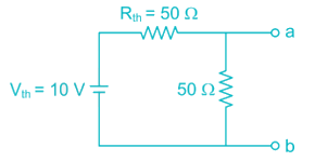
For a network Thevenin equivalent is given by Vth = 10 V and Rth = 50 Ω. If this network is shunted by another 50 Ω ……… at load. What is the new Thevenin equivalent of the network?

Detailed Solution for Test: Electrical Circuits- 3 - Question 7

Now voltage across terminal a - b is

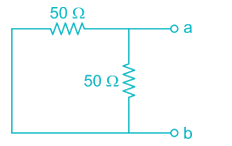
The Thevenin’s resistance can be find by neglecting the voltages source.

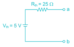
Rab = 25 Ω

New Thevenin equivalent network is,


Test: Electrical Circuits- 3 - Question 8

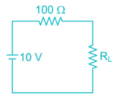
A circuit consists of three elements connected in series; 10 V battery, 100 Ω and load resistor RL. The maximum power that can be delivered to load would be?

Detailed Solution for Test: Electrical Circuits- 3 - Question 8

For maximum power transfer, RL = Rth = 100 Ω

Maximumpower

Test: Electrical Circuits- 3 - Question 9

Which of the following statements is/are correct about Norton Theorem?

A) The value of the current source is the short circuit current between the two terminals of the network.

B) Resistance is the equivalent resistance measured between the terminals of the network with all the energy. Sources are replaced by their internal resistance.

Detailed Solution for Test: Electrical Circuits- 3 - Question 9

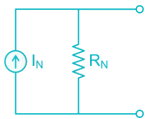
Norton’s network for any given network can be represented as

The value of the current source is the short circuit current between the two terminals of the network

Norton’s Resistance is the equivalent resistance measured between the terminals of the network with all the energy. Sources are replaced by their internal resistance.

Test: Electrical Circuits- 3 - Question 10

A current source and a voltage source are connected in parallel with a resistor as shown below. Suppose that vs = 15 V, is = 5A and R = 5 Ω. What is the current i in the resistor and the power absorbed by the resistor?

Detailed Solution for Test: Electrical Circuits- 3 - Question 10

Voltage across resistor R = 15 V

Current(I) = 15/5 = 3A

Power absorbed by resistor =(15)2/5 = 45W

Test: Electrical Circuits- 3 - Question 11

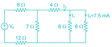
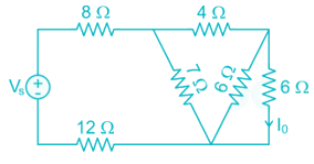
For the network shown in the following figure the value of Vs which makes I0 = 7.5 mA is:
Detailed Solution for Test: Electrical Circuits- 3 - Question 11

Given that, I0 = 7.5 mA

Hence, I1 = 7.5 mA

I2 = I0 + I1 = 15 mA

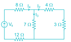
Now we can reduce the diagram,


As, I2 = 15 mA, I3 = 15 mA

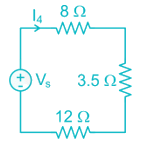
I4 = I2 + I3 = 30 mA

Now, the circuit becomes

⇒ Vs = I4 (Req) = 30 × 10-3 × (8 + 3.5 + 12) = 705 mV

Test: Electrical Circuits- 3 - Question 12

Which statement about electrical network and electrical circuit is CORRECT?

Detailed Solution for Test: Electrical Circuits- 3 - Question 12

An Electrical network is an interconnection of various electrical elements.

An electrical circuit is a network which has a closed path that gives the return path for the flow of current.

Electrical networks can either be closed or open.

Hence every electrical circuit is a network, but all networks are not circuits.

Test: Electrical Circuits- 3 - Question 13

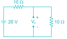
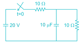
In the figure given below, the initial capacitor voltage is zero. Then after switch is closes at t = 0, Calculate the final steady state voltage across the circuit:
Detailed Solution for Test: Electrical Circuits- 3 - Question 13

At steady state, the capacitor acts as open circuit.


Test: Electrical Circuits- 3 - Question 14

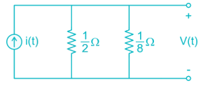
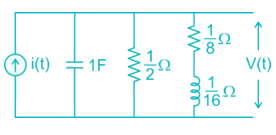
Consider the following given figure and calculate steady-state value of v(t) if i(t) is a unit step current.
Detailed Solution for Test: Electrical Circuits- 3 - Question 14

At steady state inductor acts as short circuit and the capacitor acts as open circuit.


Test: Electrical Circuits- 3 - Question 15

An ac voltage has frequency of 50 Hz with peak amplitude of 100 V. In how many seconds after the zero value, voltage will attain the value of 86.6 V?

Detailed Solution for Test: Electrical Circuits- 3 - Question 15

Given that, Vm = 100 V

V = 86.6 V

f = 50 ⇒ ω = 2πf = 100 π

V = Vm sin ωt

⇒ 86.6 = 100 sin (100 πt)

⇒ sin (100 πt) = 0.866

Test: Electrical Circuits- 3 - Question 16

In an RL series circuit, the current flowing is 5 A, the voltage drop across R is 16 V and the voltage drop across L is 12 V. Then what is the impedance?

Detailed Solution for Test: Electrical Circuits- 3 - Question 16

Given that, I = 5A, VR = 16 V, VL = 12 V

Test: Electrical Circuits- 3 - Question 17

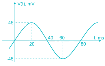
Express the voltage shown below in the general form v(t) = Vm sin (ωt + θ).
Detailed Solution for Test: Electrical Circuits- 3 - Question 17

V(t) = Vm sin (ωt + θ)

From the given wave form,

Vm = 45

Time period, T = 80 ms

ω = 2πf = 25 π

V(t) = 45 sin (25 πt + 0)

Test: Electrical Circuits- 3 - Question 18

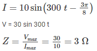
A current  is produced when a voltage V = 30 sin 300 t is applied to a circuit. The estimated value of impedance is:

Detailed Solution for Test: Electrical Circuits- 3 - Question 18

Test: Electrical Circuits- 3 - Question 19

Two circuits having the same magnitudes of impedances are joined in parallel. The power factor of one circuit is 0.8 and of other is 0.6. The power factor of the combination is -

Detailed Solution for Test: Electrical Circuits- 3 - Question 19

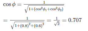
Power factor of first circuit = 0.8 (cos ϕ1)

Power factor of second circuit = 0.6 (cos ϕ2)

The power factor of parallel combination,

Test: Electrical Circuits- 3 - Question 20

For parallel RLC circuit, which of the following statements is not correct?

Detailed Solution for Test: Electrical Circuits- 3 - Question 20

1) The bandwidth of a parallel RLC circuit is decreases by increasing the resistance

2) The bandwidth is independent of inductance. Hence the bandwidth of the circuit remains the same, if L is increased

3) At resonance the impedance is equal to resistance, it behaves as a pure resistive circuit. Hence the input impedance is a real quantity

4) At resonance, the impedance is equal to resistance. It is the maximum value of impedance and hence current attains its minimum

2 videos|1 docs|55 tests
Information about Test: Electrical Circuits- 3 Page
In this test you can find the Exam questions for Test: Electrical Circuits- 3 solved & explained in the simplest way possible. Besides giving Questions and answers for Test: Electrical Circuits- 3, EduRev gives you an ample number of Online tests for practice

Top Courses for Electrical Engineering (EE)

Download as PDF

Top Courses for Electrical Engineering (EE)