Electrical Engineering (EE) Exam  >  Electrical Engineering (EE) Tests  >  GATE Electrical Engineering (EE) Mock Test Series 2025  >  Test: Electrical & Electronic Measurements- 3 - Electrical Engineering (EE) MCQ

Test: Electrical & Electronic Measurements- 3 - Electrical Engineering (EE) MCQ


Test Description

10 Questions MCQ Test GATE Electrical Engineering (EE) Mock Test Series 2025 - Test: Electrical & Electronic Measurements- 3

Test: Electrical & Electronic Measurements- 3 for Electrical Engineering (EE) 2024 is part of GATE Electrical Engineering (EE) Mock Test Series 2025 preparation. The Test: Electrical & Electronic Measurements- 3 questions and answers have been prepared according to the Electrical Engineering (EE) exam syllabus.The Test: Electrical & Electronic Measurements- 3 MCQs are made for Electrical Engineering (EE) 2024 Exam. Find important definitions, questions, notes, meanings, examples, exercises, MCQs and online tests for Test: Electrical & Electronic Measurements- 3 below.
Solutions of Test: Electrical & Electronic Measurements- 3 questions in English are available as part of our GATE Electrical Engineering (EE) Mock Test Series 2025 for Electrical Engineering (EE) & Test: Electrical & Electronic Measurements- 3 solutions in Hindi for GATE Electrical Engineering (EE) Mock Test Series 2025 course. Download more important topics, notes, lectures and mock test series for Electrical Engineering (EE) Exam by signing up for free. Attempt Test: Electrical & Electronic Measurements- 3 | 10 questions in 30 minutes | Mock test for Electrical Engineering (EE) preparation | Free important questions MCQ to study GATE Electrical Engineering (EE) Mock Test Series 2025 for Electrical Engineering (EE) Exam | Download free PDF with solutions
Test: Electrical & Electronic Measurements- 3 - Question 1

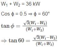
A 3 phase 500 V motor load has a power factor of 0.5. Two wattmeter’s connected to measure the input. They show the input to be 36 kW. The readings of both the instruments are.

Detailed Solution for Test: Electrical & Electronic Measurements- 3 - Question 1


⇒ W1 – W2 = 36
⇒ W1 = 36 kW, W2 = 0 kW

*Answer can only contain numeric values
Test: Electrical & Electronic Measurements- 3 - Question 2

Two wattmeter’s are connected to measure the power consumed by a 3-phase balanced load one of the wattmeter’s reads 1400 W and the other is 800 W. The power factor of the load is when both the readings are positive.


Detailed Solution for Test: Electrical & Electronic Measurements- 3 - Question 2

P1 = 1400 W, P2 = 800 W

= 25.28°
Power factor, cos ϕ = cos 25.28° = 0.90

1 Crore+ students have signed up on EduRev. Have you? Download the App
Test: Electrical & Electronic Measurements- 3 - Question 3

In a particular test, the readings of two watt meters are 5 kW, 2 kW. Then the total power and power factor are, if second wattmeter connections are reversed

Detailed Solution for Test: Electrical & Electronic Measurements- 3 - Question 3

W1 = 5kW,W2 = 2kW
Total power, P = W1 − W2 = 3kW
Power factor is,

*Answer can only contain numeric values
Test: Electrical & Electronic Measurements- 3 - Question 4

Calculate the magnitude of line current in the circuit shown in figure.


Detailed Solution for Test: Electrical & Electronic Measurements- 3 - Question 4

Impedance/ph = 1 + 1j + 7 + 5j = (8 + 6j)

Test: Electrical & Electronic Measurements- 3 - Question 5

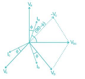
In the balanced three phase circuit shown in figure, the current coil of the wattmeter is connected in line aA, and the potential coil of the wattmeter us connected across lines b and c. The phase sequence is positive and the load power factor is 0.8 lag. The wattmeter reading will be

Detailed Solution for Test: Electrical & Electronic Measurements- 3 - Question 5

Current through current coil = Ia
Voltage across the pressure coil = Vbc

Wattmeter reading = Vbc Ia cos(90 - ϕ)
= Vbc Ia sin ϕ
= (200) (5) (0.6) = 600 W

Test: Electrical & Electronic Measurements- 3 - Question 6

A 5A, 110V electrodynamic type wattmeter has a scale having 110 divisions. Its pressure coil is fed by a voltage of  [110√2cos(314t) + √2sin(942t)]  V and is current coil carries a current of [5√2cos(314t + 60) + 2√2sin(628t + 90) + √2cos(642t + 90)] A. The needle of the wattmeter will move to

Detailed Solution for Test: Electrical & Electronic Measurements- 3 - Question 6

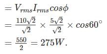
The average power read by the meter is

Full scale reading of wattmeter = 110 × 5 = 550 W
Scale having 110 divisions for 550 W reading.
Hence number of divisions required for 275 W
 = 110/2 = 55

*Answer can only contain numeric values
Test: Electrical & Electronic Measurements- 3 - Question 7

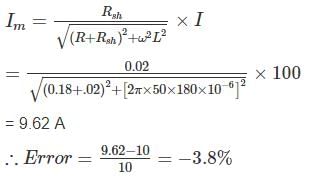
The constant of the shunt to extend the range 0-10 A moving iron ammeter to 0-100 A, the instrument constant are R = 0.18 Ω and L = 180 μH. If the shunt is made non-inductive and the combination is correct on dc. Find the full-scale error (in percentage) at 50 Hz.


Detailed Solution for Test: Electrical & Electronic Measurements- 3 - Question 7

Multiplying power of shut 
∴ Resistance of shunt 
Time constant of shunt and meter should be equal

The current through the meter 

With 50 Hz the current through the meter

*Answer can only contain numeric values
Test: Electrical & Electronic Measurements- 3 - Question 8

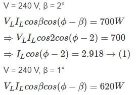
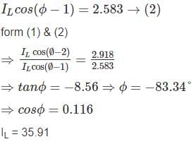
The reading of a dynamometer – type wattmeter with pressure coil phase angle of 2° is 700 watts, when it is used to measure power of a single phase inductive load supplied by 240 V single phase ac. source. when the wattmeter is replaced by a second wattmeter with a phase angle of 1° for the pressure coil circuit, a reading of 620 watts is obtained. Assuming all errors of the wattmeter, except those due to pressure coil inductance are neglected. The actual power is ____________(in W)


Detailed Solution for Test: Electrical & Electronic Measurements- 3 - Question 8


True power = VLILcosϕ = 240 × 35.91 × 0.116
= 999.9 W

Test: Electrical & Electronic Measurements- 3 - Question 9

A wattmeter reads 5.54 kW when its current coil is connected in the red phase and its voltage coil is connected between the neutral and red phase of a symmetrical three phase system supplying a balanced load of 30 A at 400 V. What will be the reading of the instrument if the current coil remains unchanged and voltage coil be connected between blue and yellow phases. The phase sequence is RYB.

Detailed Solution for Test: Electrical & Electronic Measurements- 3 - Question 9

Let V and I be the phase voltage and phase current respectively.

Phase current = 30 A
In the first case, the wattmeter measures the power in one phase.
VI cos ϕ = 5.54 × 10³

When the current coil is connected in the red phase and the pressure coil circuit is connected across the yellow and blue phase, the reading of wattmeter is, 

*Answer can only contain numeric values
Test: Electrical & Electronic Measurements- 3 - Question 10

The balanced three phase load shown in figure is fed form a balanced, positive sequence, there phase Y-connected source. The impedance of the line connecting the source to the load is negligible the line to neutral voltage of the source is 7200 V. Find the reading of the wattmeter in kW.
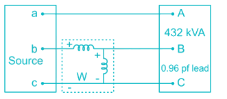

Detailed Solution for Test: Electrical & Electronic Measurements- 3 - Question 10


VBN = 7200 ∠-120°V
VCN = 7200 ∠120°V

IbB = 20 ∠-103.74°A
W = VIcosϕ = (7200)(√3)(20)cos(−90+103.74)
= 242.28 kW

25 docs|247 tests
Information about Test: Electrical & Electronic Measurements- 3 Page
In this test you can find the Exam questions for Test: Electrical & Electronic Measurements- 3 solved & explained in the simplest way possible. Besides giving Questions and answers for Test: Electrical & Electronic Measurements- 3, EduRev gives you an ample number of Online tests for practice

Top Courses for Electrical Engineering (EE)

Download as PDF

Top Courses for Electrical Engineering (EE)